The OSI Model and the TCP/IP Protocol Suite


57 Slides1.32 MB
The OSI Model and the TCP/IP Protocol Suite
OBJECTIVES To discuss the idea of multiple layering in data communication and networking and the interrelationship between layers. To discuss the OSI model and its layer architecture and to show the interface between the layers. To briefly discuss the functions of each layer in the OSI model. To introduce the TCP/IP protocol suite and compare its layers with the ones in the OSI model. To show the functionality of each layer in the TCP/IP protocol with some examples. To discuss the addressing mechanism used in some layers of the TCP/IP protocol suite for the delivery of a message from the source to the destination.
Introduction The layered model that dominated data communication and networking literature before 1990 was the Open Systems Interconnection (OSI) model. Everyone believed that the OSI model would become the ultimate standard for data communications—but this did not happen. The TCP/IP protocol suite became the dominant commercial architecture because it was used and tested extensively in the Internet; the OSI model was never fully implemented.
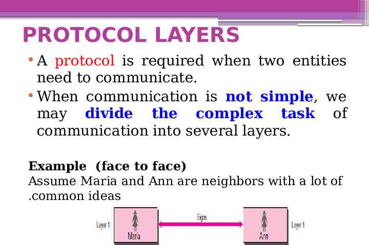
PROTOCOL LAYERS A protocol is required when two entities need to communicate. When communication is not simple, we may divide the complex task of communication into several layers. Example (face to face) Assume Maria and Ann are neighbors with a lot of .common ideas
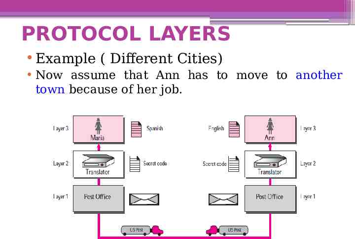
PROTOCOL LAYERS Example ( Different Cities) Now assume that Ann has to move to another town because of her job.
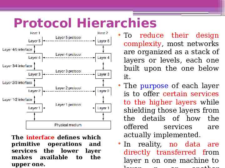
Protocol Hierarchies The interface defines which primitive operations and services the lower layer makes available to the upper one. To reduce their design complexity, most networks are organized as a stack of layers or levels, each one built upon the one below it. The purpose of each layer is to offer certain services to the higher layers while shielding those layers from the details of how the offered services are actually implemented. In reality, no data are directly transferred from layer n on one machine to
THE OSI MODEL This model is based on a proposal developed by the International Standards Organization (ISO) as a first step toward international standardization of the protocols used in the various layers. The model is called the Open Systems Interconnection (OSI) Reference Model because it deals with connecting open systems. It was first introduced in the late 1970s. An open system is a set of protocols that allows any two different systems to communicate regardless of their underlying architecture.
THE OSI MODEL The purpose of the OSI model is to show how to facilitate communication between different systems without requiring changes to the logic of the underlying hardware and software. The OSI model is not a protocol; it is a model for understanding and designing a network architecture that is flexible, robust, and interoperable. The OSI model is a layered framework for the design of network systems that allows communication between all types of computer systems.
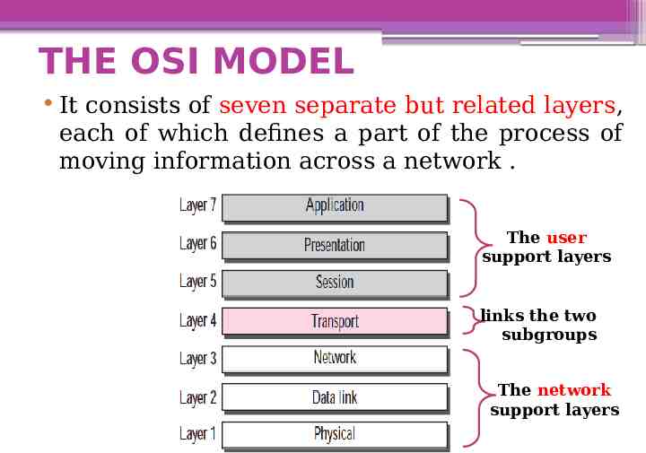
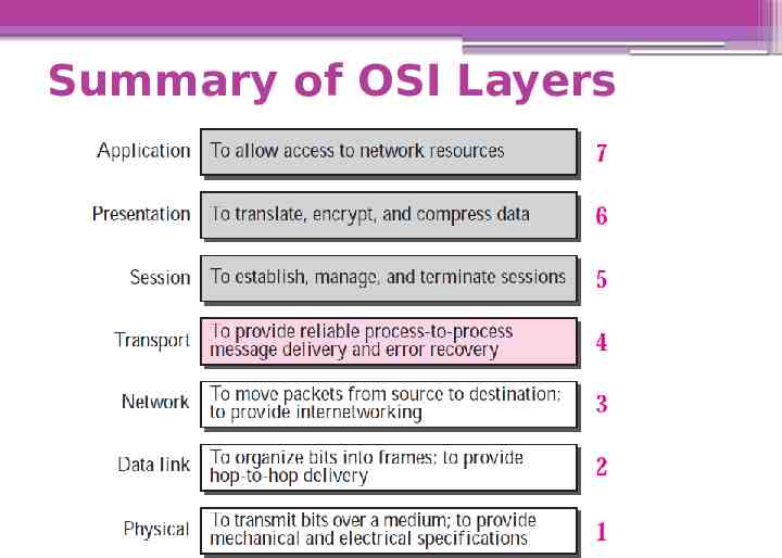
THE OSI MODEL It consists of seven separate but related layers, each of which defines a part of the process of moving information across a network . The user support layers links the two subgroups The network support layers
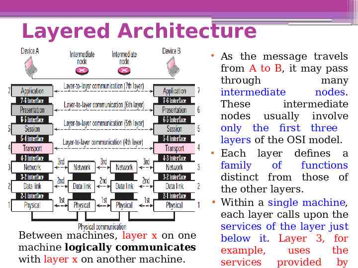
Layered Architecture Between machines, layer x on one machine logically communicates with layer x on another machine. As the message travels from A to B, it may pass through many intermediate nodes. These intermediate nodes usually involve only the first three layers of the OSI model. Each layer defines a family of functions distinct from those of the other layers. Within a single machine, each layer calls upon the services of the layer just below it. Layer 3, for example, uses the services provided by
Layered Architecture Interfaces between Layers: Each interface defines what information and services a layer must provide for the layer above it. The upper OSI layers are almost always implemented in software; lower layers are a combination of hardware and software, except for the physical layer, which is mostly hardware.
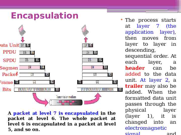
Encapsulation The process starts at layer 7 (the application layer), then moves from layer to layer in Data Unit descending, PPDU sequential order. At SPDU each layer, a Segmen header can be added to the data Packett unit. At layer 2, a Frame trailer may also be Bits added. When the formatted data unit passes through the physical layer A packet at level 7 is encapsulated in the (layer 1), it is packet at level 6. The whole packet at changed into an level 6 is encapsulated in a packet at level electromagnetic 5, and so on.
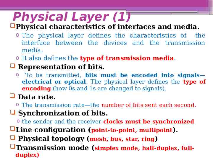
Physical Layer (1) The physical layer coordinates the functions required to carry a bit stream over a physical medium. It deals with the mechanical and electrical specifications of the interface and transmission media. It also defines the procedures and functions that physical devices and interfaces have to perform for transmission to occur.
Physical Layer (1) Physical characteristics of interfaces and media. o The physical layer defines the characteristics of the interface between the devices and the transmission media. o It also defines the type of transmission media. Representation of bits. o To be transmitted, bits must be encoded into signals— electrical or optical. The physical layer defines the type of encoding (how 0s and 1s are changed to signals). Data rate. o The transmission rate—the number of bits sent each second. Synchronization of bits. o the sender and the receiver clocks must be synchronized. Line configuration (point-to-point, multipoint). Physical topology (mesh, bus, star, ring) Transmission mode (simplex mode, half-duplex, fullduplex)
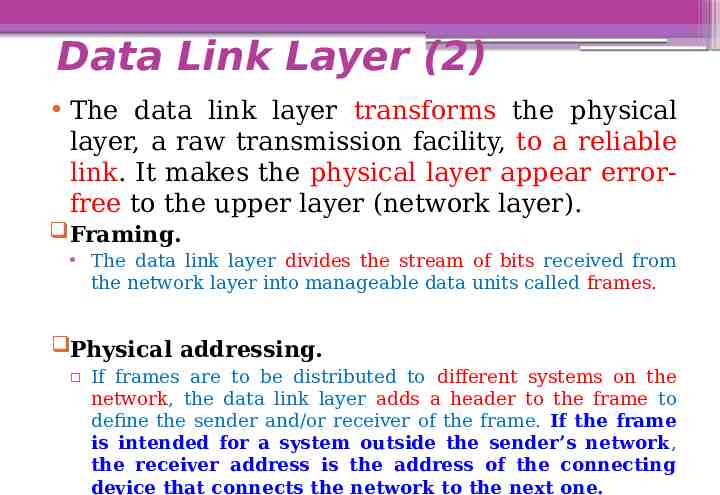
Data Link Layer (2) The data link layer transforms the physical layer, a raw transmission facility, to a reliable link. It makes the physical layer appear errorfree to the upper layer (network layer). Framing. The data link layer divides the stream of bits received from the network layer into manageable data units called frames. Physical addressing. If frames are to be distributed to different systems on the network, the data link layer adds a header to the frame to define the sender and/or receiver of the frame. If the frame is intended for a system outside the sender’s network, the receiver address is the address of the connecting device that connects the network to the next one.
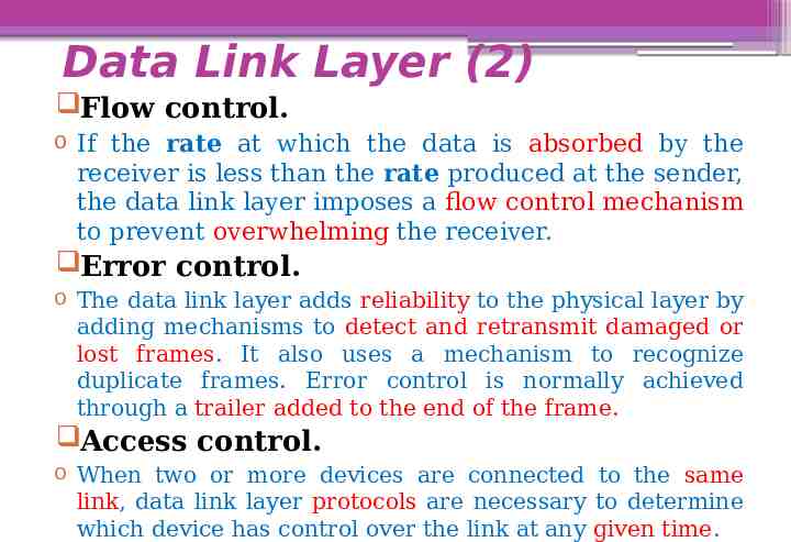
Data Link Layer (2) Flow control. o If the rate at which the data is absorbed by the receiver is less than the rate produced at the sender, the data link layer imposes a flow control mechanism to prevent overwhelming the receiver. Error control. o The data link layer adds reliability to the physical layer by adding mechanisms to detect and retransmit damaged or lost frames. It also uses a mechanism to recognize duplicate frames. Error control is normally achieved through a trailer added to the end of the frame. Access control. o When two or more devices are connected to the same link, data link layer protocols are necessary to determine which device has control over the link at any given time.
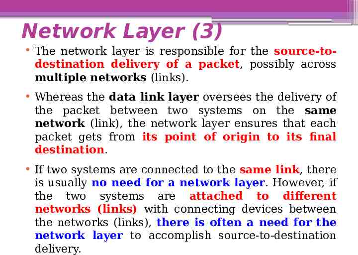
Network Layer (3) The network layer is responsible for the source-todestination delivery of a packet, possibly across multiple networks (links). Whereas the data link layer oversees the delivery of the packet between two systems on the same network (link), the network layer ensures that each packet gets from its point of origin to its final destination. If two systems are connected to the same link, there is usually no need for a network layer. However, if the two systems are attached to different networks (links) with connecting devices between the networks (links), there is often a need for the network layer to accomplish source-to-destination delivery.
Network Layer (3) Logical addressing. o The physical addressing implemented by the data link layer handles the addressing problem locally. If a packet passes the network boundary, we need another addressing system to help distinguish the source and destination systems. The network layer adds a header to the packet coming from the upper layer that, among other things, includes the logical addresses of the sender and receiver. Routing. o When independent networks or links are connected together to create internetworks (network of networks) or a large network, the connecting devices (called routers or switches) route or switch the packets to their final destination. One of the functions of the network layer is to provide this mechanism.
Transport Layer(4) The transport layer is responsible for process-to-process delivery of the entire message. A process is an application program running on the host. The transport layer, ensures that the whole message arrives intact and in order. Service-point addressing. o The transport layer header must add a type of address called a service-point address (or port address). The network layer gets each packet to the correct computer; the transport layer gets the entire message to the correct process on that computer.
Transport Layer(4) Segmentation and reassembly. o A message is divided into transmittable segments, with each segment containing a sequence number. These numbers enable the transport layer to reassemble the message correctly upon arriving at the destination and to identify and replace packets that were lost in transmission. Connection control. o The transport layer can be either connectionless or connection-oriented. Flow control. o Like the data link layer, the transport layer is responsible for flow control. However, flow control at this layer is performed end to end rather than across a single link. Error control. o Like the data link layer, the transport layer is responsible for error control. However, error control at this layer is performed process-to-process rather than across a single link. Error correction is usually achieved through retransmission.
Session Layer(5) The session layer is the network dialog controller. It establishes, maintains, and synchronizes the interaction between communicating systems. Dialog control. The session layer allows two systems to enter into a dialog. It allows the communication between two processes to take place in either half-duplex or fullduplex mode. Synchronization. The session layer allows a process to add checkpoints (synchronization points) into a stream of data. For example, if a system is sending a file of 2,000 pages, it is advisable to insert checkpoints after every 100 pages to ensure that each 100-page unit is received and acknowledged independently. In this case, if a crash happens during the transmission of page 523, the only
Presentation Layer (6) The presentation layer is concerned with the syntax and semantics of the information exchanged between two systems. Translation. o The presentation layer is responsible for interoperability between these different encoding methods. o The presentation layer at the sender changes the information from its sender-dependent format into a common format. The presentation layer at the receiving machine changes the common format into its receiver-dependent format. Encryption. Compression.
Application Layer (7) The application layer enables the user, whether human or software, to access the network. It provides user interfaces and support for services such as electronic mail, remote file access and transfer, shared database management, and other types of distributed information services.
Summary of OSI Layers
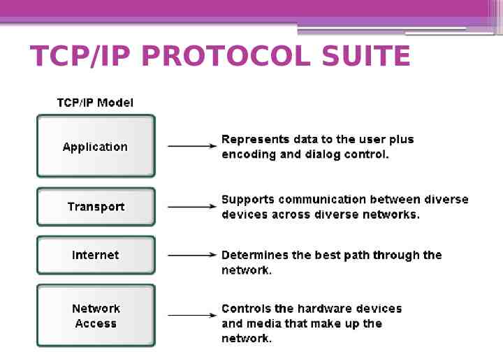
TCP/IP PROTOCOL SUITE The first layered protocol model for internetwork communications was created in the early 1970s and is referred to as the Internet model. It defines four categories of functions that must occur for communications to be successful. The architecture of the TCP/IP protocol suite follows the structure of this model. Because of this, the Internet model is commonly referred to as the TCP/IP model. The TCP/IP protocol suite was developed prior to the OSI model. Therefore, the layers in the TCP/IP protocol suite do not match exactly with those in the OSI model. The original TCP/IP protocol suite was defined as four software layers built upon the hardware.
TCP/IP PROTOCOL SUITE
TCP/IP PROTOCOL SUITE
TCP/IP PROTOCOL SUITE
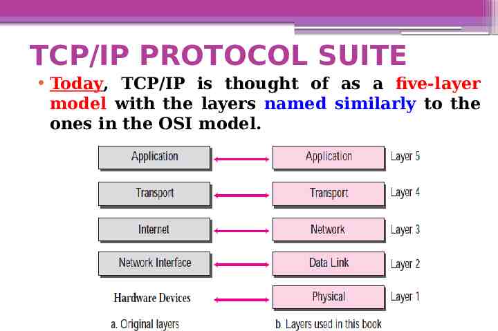
TCP/IP PROTOCOL SUITE Today, TCP/IP is thought of as a five-layer model with the layers named similarly to the ones in the OSI model.
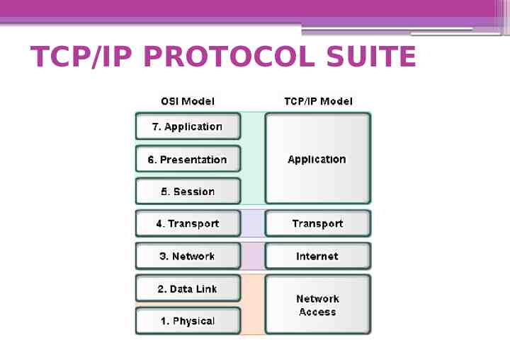
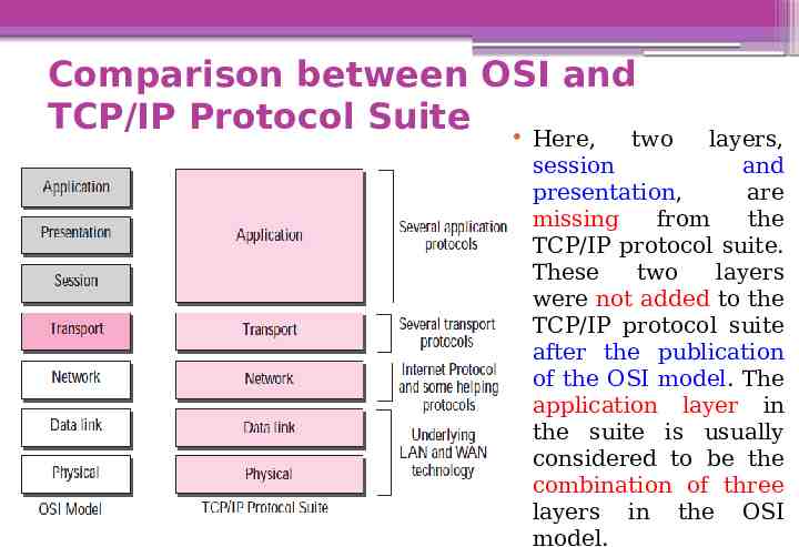
Comparison between OSI and TCP/IP Protocol Suite Here, two layers, session and presentation, are missing from the TCP/IP protocol suite. These two layers were not added to the TCP/IP protocol suite after the publication of the OSI model. The application layer in the suite is usually considered to be the combination of three layers in the OSI model.
Comparison between OSI and TCP/IP Protocol Suite Two reasons were mentioned for this decision. First, TCP/IP has more than one transport-layer protocol. Some of the functionalities of the session layer are available in some of the transport layer protocols. Second, the application layer is not only one piece of software. Many applications can be developed at this layer. If some of the functionalities mentioned in the session and presentation are needed for a particular application, it can be included in the development of that piece of software.
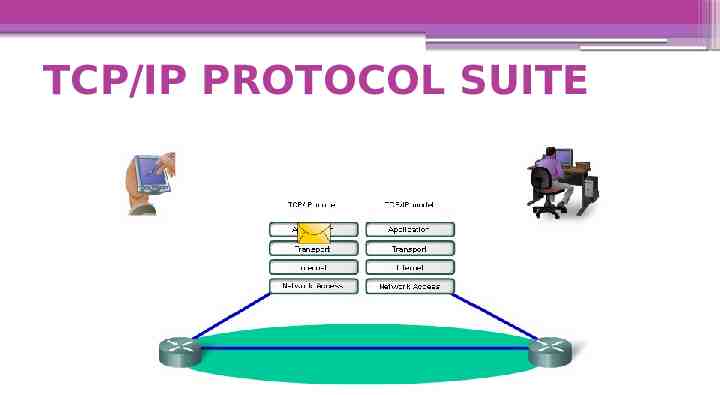
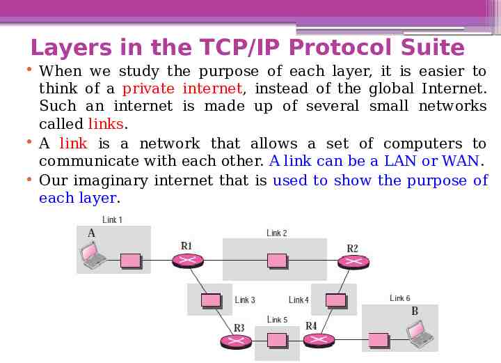
Layers in the TCP/IP Protocol Suite When we study the purpose of each layer, it is easier to think of a private internet, instead of the global Internet. Such an internet is made up of several small networks called links. A link is a network that allows a set of computers to communicate with each other. A link can be a LAN or WAN. Our imaginary internet that is used to show the purpose of each layer.
Physical Layer (1) TCP/IP TCP/IP does not define any specific protocol for the physical layer. It supports all of the standard and proprietary protocols. At this level, the communication is between two hops or nodes, either a computer or router. The unit of communication is a single bit. When the connection is established between the two nodes, a stream of bits is flowing between them. The physical layer, however, treats each bit individually.
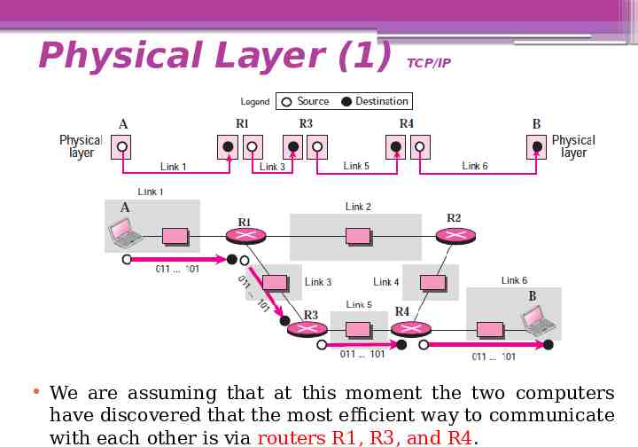
Physical Layer (1) TCP/IP We are assuming that at this moment the two computers have discovered that the most efficient way to communicate with each other is via routers R1, R3, and R4.
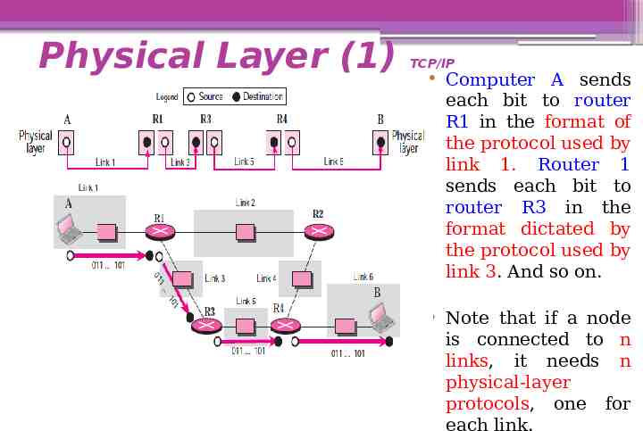
Physical Layer (1) TCP/IP Computer A sends each bit to router R1 in the format of the protocol used by link 1. Router 1 sends each bit to router R3 in the format dictated by the protocol used by link 3. And so on. Note that if a node is connected to n links, it needs n physical-layer protocols, one for each link.
Data Link Layer (2) TCP/IP TCP/IP does not define any specific protocol for the data link layer either. It supports all of the standard and proprietary protocols. At this level, the communication is also between two hops or nodes. The unit of communication however, is a packet called a frame. A frame is a packet that encapsulates the data received from the network layer with an added header and sometimes a trailer. The head includes the source and destination of frame. The destination address is needed to define the right recipient of the frame. The source address is needed for possible response or acknowledgment as may be required by some protocols.
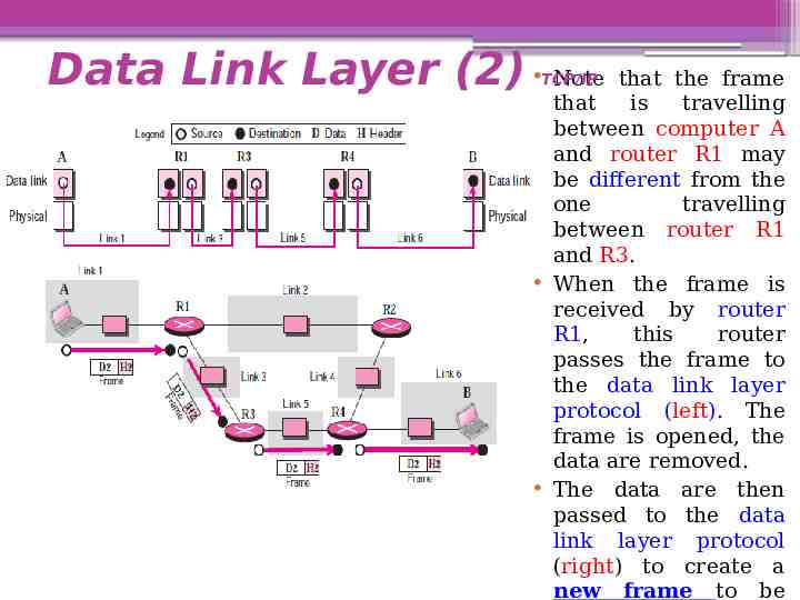
Data Link Layer (2) Note that the frame that is travelling between computer A and router R1 may be different from the one travelling between router R1 and R3. When the frame is received by router R1, this router passes the frame to the data link layer protocol (left). The frame is opened, the data are removed. The data are then passed to the data link layer protocol (right) to create a new frame to be TCP/IP
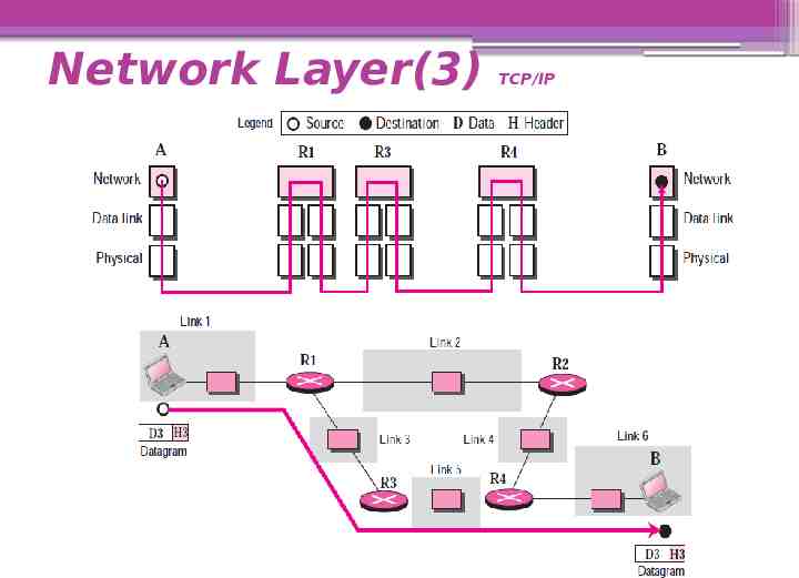
Network Layer(3) TCP/IP At the network layer (or, more accurately, the internetwork layer), TCP/IP supports the Internet Protocol (IP). The Internet Protocol (IP) is the transmission mechanism used by the TCP/IP protocols. IP transports data in packets called Datagrams, each of which is transported separately. Datagrams can travel along different routes and can arrive out of sequence or be duplicated. IP does not keep track of the routes and has no facility for reordering datagrams once they arrive at their destination.
Network Layer(3) TCP/IP
Network Layer(3) TCP/IP Note that there is a main difference between the communication at the network layer and the communication at data link or physical layers: Communication at the network layer is end to end while the communication at the other two layers are node to node. The datagram started at computer A is the one that reaches computer B. The network layers of the routers can inspect (check) the source and destination of the packet for finding the best route, but they are not allowed to change the contents of the packet.
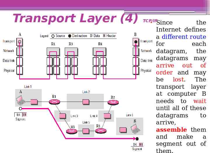
Transport Layer (4) TCP/IP There is a main difference between the transport layer and the network layer. Although all nodes in a network need to have the network layer, only the two end computers need to have the transport layer. The network layer is responsible for sending individual datagrams from computer A to computer B; the transport layer is responsible for delivering the whole message, which is called a Segment, a user datagram, or a packet, from A to B. A segment may consist of a few or tens of datagrams. The segments need to be broken into datagrams and each datagram has to be delivered to the network layer for transmission.
Transport Layer (4) TCP/IP Since the Internet defines a different route for each datagram, the datagrams may arrive out of order and may be lost. The transport layer at computer B needs to wait until all of these datagrams to arrive, assemble them and make a segment out of them.
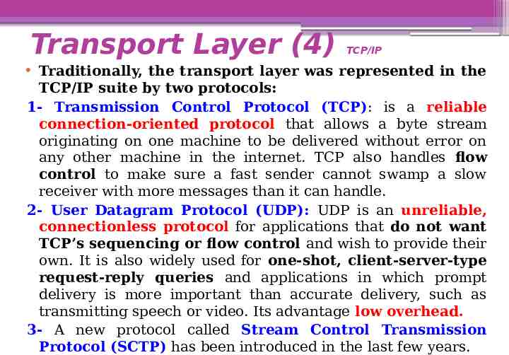
Transport Layer (4) TCP/IP Traditionally, the transport layer was represented in the TCP/IP suite by two protocols: 1- Transmission Control Protocol (TCP): is a reliable connection-oriented protocol that allows a byte stream originating on one machine to be delivered without error on any other machine in the internet. TCP also handles flow control to make sure a fast sender cannot swamp a slow receiver with more messages than it can handle. 2- User Datagram Protocol (UDP): UDP is an unreliable, connectionless protocol for applications that do not want TCP’s sequencing or flow control and wish to provide their own. It is also widely used for one-shot, client-server-type request-reply queries and applications in which prompt delivery is more important than accurate delivery, such as transmitting speech or video. Its advantage low overhead. 3- A new protocol called Stream Control Transmission Protocol (SCTP) has been introduced in the last few years.
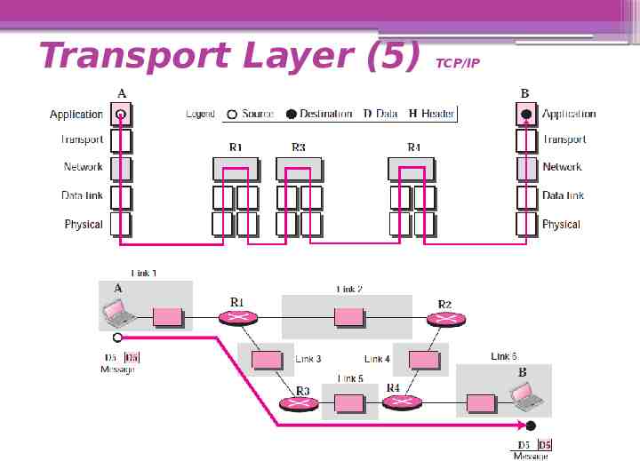
Application Layer (5) TCP/IP The application layer in TCP/IP is equivalent to the combined session, presentation, and application layers in the OSI model. The application layer allows a user to access the services of our private internet or the global Internet. Many protocols are defined at this layer to provide services such as electronic mail, file transfer, accessing the World Wide Web, and so on. Note that the communication at the application layer, like the one at the transport layer, is end to end. A message generated at computer A is sent to computer B without being changed during the transmission.
Transport Layer (5) TCP/IP
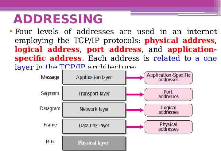
ADDRESSING Four levels of addresses are used in an internet employing the TCP/IP protocols: physical address, logical address, port address, and applicationspecific address. Each address is related to a one layer in the TCP/IP architecture:
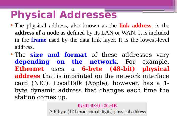
Physical Addresses The physical address, also known as the link address, is the address of a node as defined by its LAN or WAN. It is included in the frame used by the data link layer. It is the lowest-level address. The size and format of these addresses vary depending on the network. For example, Ethernet uses a 6-byte (48-bit) physical address that is imprinted on the network interface card (NIC). LocalTalk (Apple), however, has a 1byte dynamic address that changes each time the station comes up.
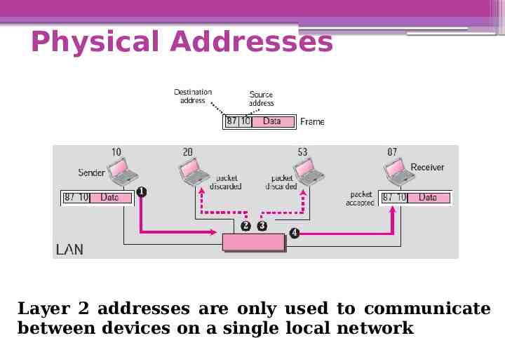
Physical Addresses Layer 2 addresses are only used to communicate between devices on a single local network
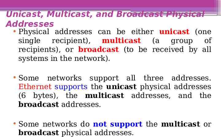
Unicast, Multicast, and Broadcast Physical Addresses Physical addresses can be either unicast (one single recipient), multicast (a group of recipients), or broadcast (to be received by all systems in the network). Some networks support all three addresses. Ethernet supports the unicast physical addresses (6 bytes), the multicast addresses, and the broadcast addresses. Some networks do not support the multicast or broadcast physical addresses.
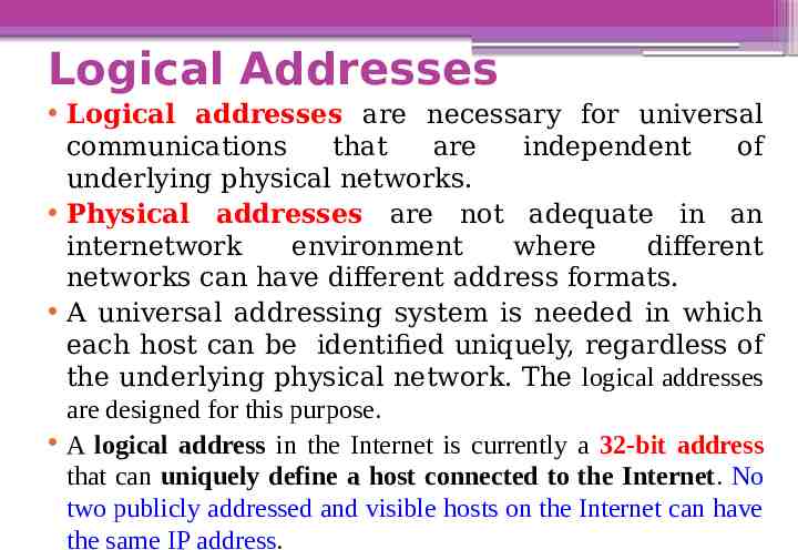
Logical Addresses Logical addresses are necessary for universal communications that are independent of underlying physical networks. Physical addresses are not adequate in an internetwork environment where different networks can have different address formats. A universal addressing system is needed in which each host can be identified uniquely, regardless of the underlying physical network. The logical addresses are designed for this purpose. A logical address in the Internet is currently a 32-bit address that can uniquely define a host connected to the Internet. No two publicly addressed and visible hosts on the Internet can have the same IP address.
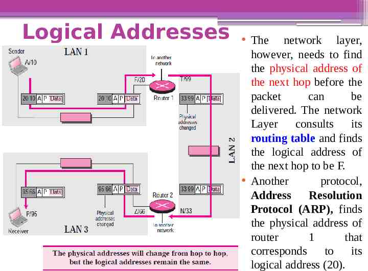
Logical Addresses The network layer, however, needs to find the physical address of the next hop before the packet can be delivered. The network Layer consults its routing table and finds the logical address of the next hop to be F. Another protocol, Address Resolution Protocol (ARP), finds the physical address of router 1 that corresponds to its logical address (20).
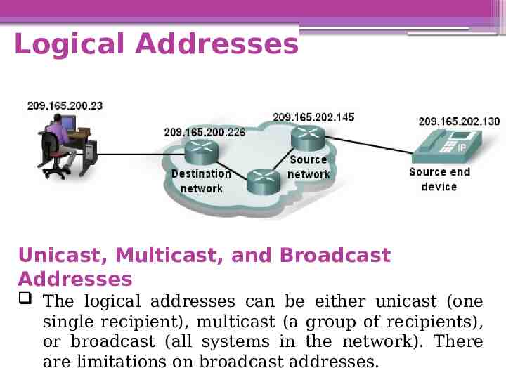
Logical Addresses Unicast, Multicast, and Broadcast Addresses The logical addresses can be either unicast (one single recipient), multicast (a group of recipients), or broadcast (all systems in the network). There are limitations on broadcast addresses.
Logical Addresses
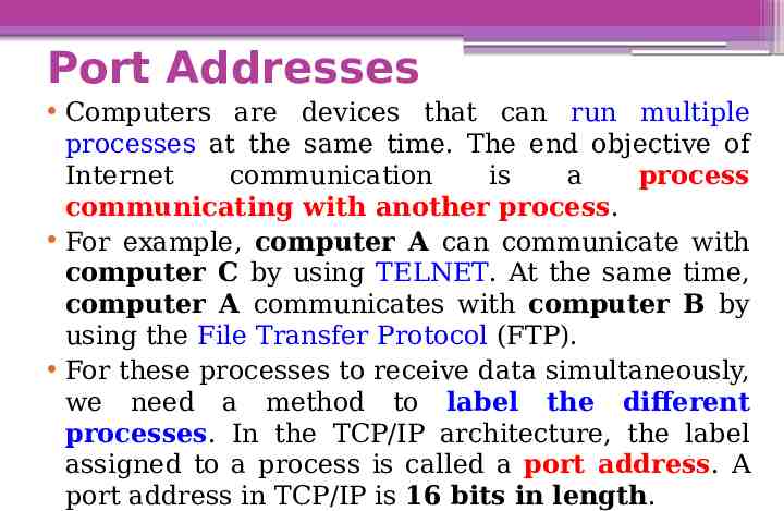
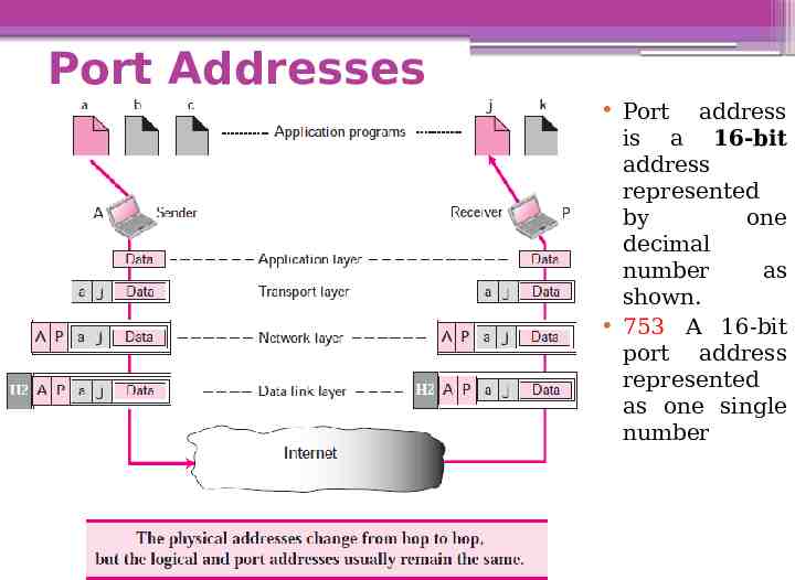
Port Addresses Computers are devices that can run multiple processes at the same time. The end objective of Internet communication is a process communicating with another process. For example, computer A can communicate with computer C by using TELNET. At the same time, computer A communicates with computer B by using the File Transfer Protocol (FTP). For these processes to receive data simultaneously, we need a method to label the different processes. In the TCP/IP architecture, the label assigned to a process is called a port address. A port address in TCP/IP is 16 bits in length.
Port Addresses Port address is a 16-bit address represented by one decimal number as shown. 753 A 16-bit port address represented as one single number
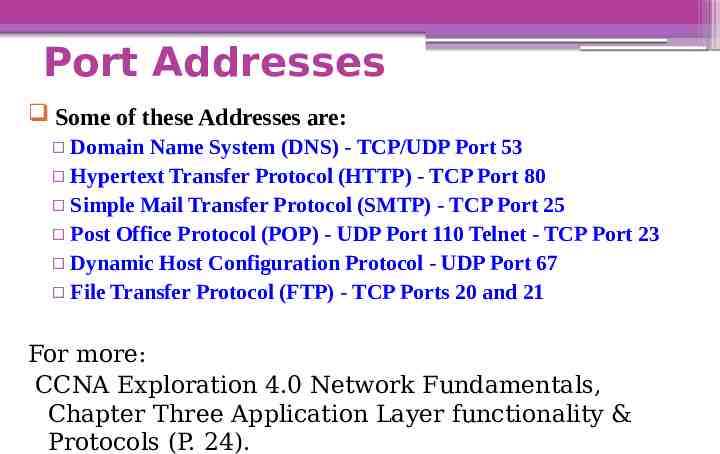
Port Addresses Some of these Addresses are: Domain Name System (DNS) - TCP/UDP Port 53 Hypertext Transfer Protocol (HTTP) - TCP Port 80 Simple Mail Transfer Protocol (SMTP) - TCP Port 25 Post Office Protocol (POP) - UDP Port 110 Telnet - TCP Port 23 Dynamic Host Configuration Protocol - UDP Port 67 File Transfer Protocol (FTP) - TCP Ports 20 and 21 For more: CCNA Exploration 4.0 Network Fundamentals, Chapter Three Application Layer functionality & Protocols (P. 24).
Application-Specific Addresses Some applications have user-friendly addresses that are designed for that specific application. Examples include the e-mail address (for example, [email protected]) and the Universal Resource Locator (URL) (for example, www.mhhe.com). The first defines the recipient of an e-mail; the second is used to find a document on the World Wide Web. These addresses, however, get changed to the corresponding port and logical addresses by the sending computer.