Mobile Handset Cellular Network


64 Slides3.46 MB
Mobile Handset Cellular Network
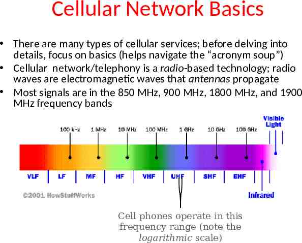
Cellular Network Basics There are many types of cellular services; before delving into details, focus on basics (helps navigate the “acronym soup”) Cellular network/telephony is a radio-based technology; radio waves are electromagnetic waves that antennas propagate Most signals are in the 850 MHz, 900 MHz, 1800 MHz, and 1900 MHz frequency bands Cell phones operate in this frequency range (note the logarithmic scale)
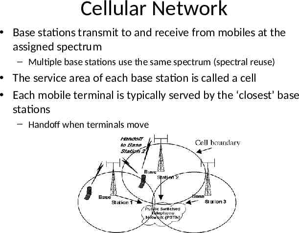
Cellular Network Base stations transmit to and receive from mobiles at the assigned spectrum – Multiple base stations use the same spectrum (spectral reuse) The service area of each base station is called a cell Each mobile terminal is typically served by the ‘closest’ base stations – Handoff when terminals move
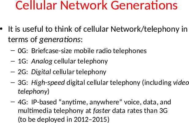
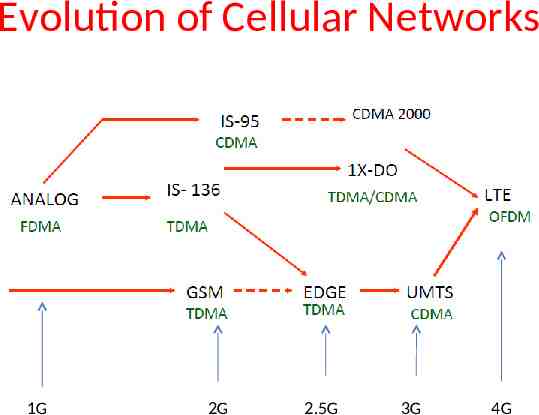
Cellular Network Generations It is useful to think of cellular Network/telephony in terms of generations: – – – – 0G: Briefcase-size mobile radio telephones 1G: Analog cellular telephony 2G: Digital cellular telephony 3G: High-speed digital cellular telephony (including video telephony) – 4G: IP-based “anytime, anywhere” voice, data, and multimedia telephony at faster data rates than 3G (to be deployed in 2012–2015)
Evolution of Cellular Networks 1G 2G 2.5G 3G 4G
The Multiple Access Problem The base stations need to serve many mobile terminals at the same time (both downlink and uplink) All mobiles in the cell need to transmit to the base station Interference among different senders and receivers So we need multiple access scheme
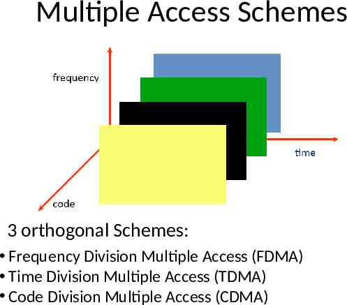
Multiple Access Schemes 3 orthogonal Schemes: Frequency Division Multiple Access (FDMA) Time Division Multiple Access (TDMA) Code Division Multiple Access (CDMA)
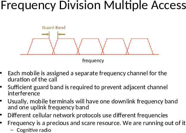
Frequency Division Multiple Access frequency Each mobile is assigned a separate frequency channel for the duration of the call Sufficient guard band is required to prevent adjacent channel interference Usually, mobile terminals will have one downlink frequency band and one uplink frequency band Different cellular network protocols use different frequencies Frequency is a precious and scare resource. We are running out of it – Cognitive radio
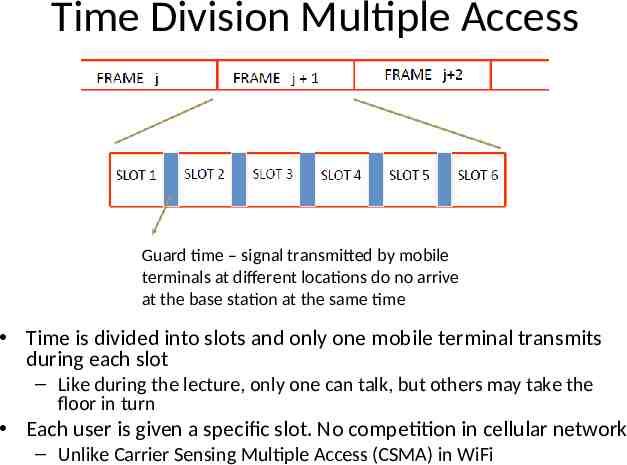
Time Division Multiple Access Guard time – signal transmitted by mobile terminals at different locations do no arrive at the base station at the same time Time is divided into slots and only one mobile terminal transmits during each slot – Like during the lecture, only one can talk, but others may take the floor in turn Each user is given a specific slot. No competition in cellular network – Unlike Carrier Sensing Multiple Access (CSMA) in WiFi
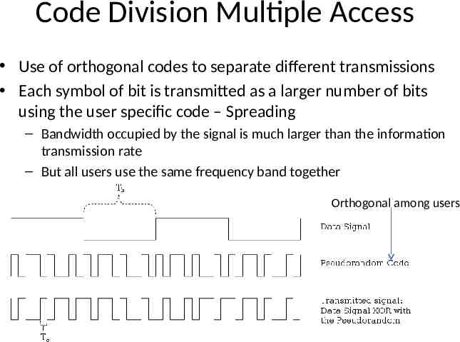
Code Division Multiple Access Use of orthogonal codes to separate different transmissions Each symbol of bit is transmitted as a larger number of bits using the user specific code – Spreading – Bandwidth occupied by the signal is much larger than the information transmission rate – But all users use the same frequency band together Orthogonal among users
2G(GSM)
GSM Abbreviation for Global System for Mobile Communications Concurrent development in USA and Europe in the 1980’s The European system was called GSM and deployed in the early 1990’s
GSM Services Voice, 3.1 kHz Short Message Service (SMS) – 1985 GSM standard that allows messages of at most 160 chars. (incl. spaces) to be sent between handsets and other stations – Over 2.4 billion people use it; multi-billion industry General Packet Radio Service (GPRS) – GSM upgrade that provides IP-based packet data transmission up to 114 kbps – Users can “simultaneously” make calls and send data – GPRS provides “always on” Internet access and the Multimedia Messaging Service (MMS) whereby users can send rich text, audio, video messages to each other – Performance degrades as number of users increase – GPRS is an example of 2.5G telephony – 2G service similar to 3G
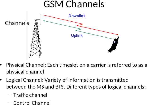
GSM Channels Downlink Channels Uplink Physical Channel: Each timeslot on a carrier is referred to as a physical channel Logical Channel: Variety of information is transmitted between the MS and BTS. Different types of logical channels: – Traffic channel – Control Channel
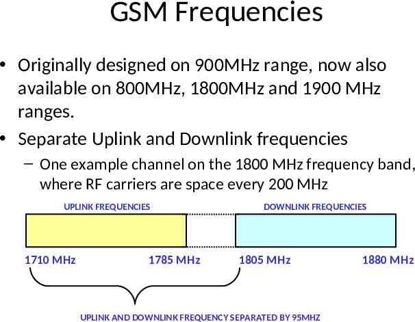
GSM Frequencies Originally designed on 900MHz range, now also available on 800MHz, 1800MHz and 1900 MHz ranges. Separate Uplink and Downlink frequencies – One example channel on the 1800 MHz frequency band, where RF carriers are space every 200 MHz UPLINK FREQUENCIES 1710 MHz 1785 MHz DOWNLINK FREQUENCIES 1805 MHz UPLINK AND DOWNLINK FREQUENCY SEPARATED BY 95MHZ 1880 MHz
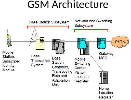
GSM Architecture
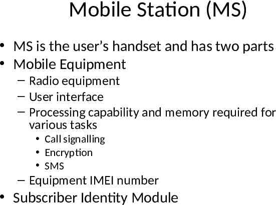
Mobile Station (MS) MS is the user’s handset and has two parts Mobile Equipment – Radio equipment – User interface – Processing capability and memory required for various tasks Call signalling Encryption SMS – Equipment IMEI number Subscriber Identity Module
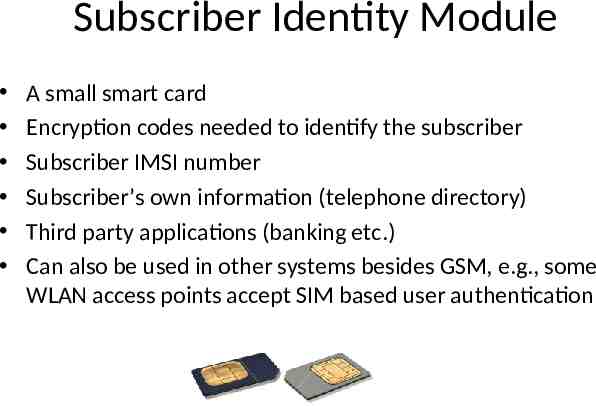
Subscriber Identity Module A small smart card Encryption codes needed to identify the subscriber Subscriber IMSI number Subscriber’s own information (telephone directory) Third party applications (banking etc.) Can also be used in other systems besides GSM, e.g., some WLAN access points accept SIM based user authentication
Base Station Subsystem Transcoding Rate and Adaptation Unit (TRAU) – Performs coding between the 64kbps PCM coding used in the backbone network and the 13 kbps coding used for the Mobile Station (MS) Base Station Controller (BSC) – Controls the channel (time slot) allocation implemented by the BTSes – Manages the handovers within BSS area – Knows which mobile stations are within the cell and informs the MSC/VLR about this Base Transceiver System (BTS) – Controls several transmitters – Each transmitter has 8 time slots, some used for signaling, on a specific frequency
Network and Switching Subsystem The backbone of a GSM network is a telephone network with additional cellular network capabilities Mobile Switching Center (MSC) – An typical telephony exchange (ISDN exchange) which supports mobile communications – Visitor Location Register (VLR) A database, part of the MSC Contains the location of the active Mobile Stations Gateway Mobile Switching Center (GMSC) – Links the system to PSTN and other operators Home Location Register (HLR) – Contain subscriber information, including authentication information in Authentication Center (AuC) Equipment Identity Register (EIR) – International Mobile Station Equipment Identity (IMEI) codes for e.g., blacklisting stolen phones
Home Location Register One database per operator Contains all the permanent subscriber information – MSISDN (Mobile Subscriber ISDN number) is the telephone number of the subscriber – International Mobile Subscriber Identity (IMSI) is a 15 digit code used to identify the subscriber It incorporates a country code and operator code – IMSI code is used to link the MSISDN number to the subscriber’s SIM (Subscriber Identity Module) – Charging information – Services available to the customer Also the subscriber’s present Location Area Code, which refers to the MSC, which can connect to the MS.
Other Systems Operations Support System – The management network for the whole GSM network – Usually vendor dependent – Very loosely specified in the GSM standards Value added services – Voice mail – Call forwarding – Group calls Short Message Service Center – Stores and forwards the SMS messages – Like an E-mail server – Required to operate the SMS services
Location Updates The cells overlap and usually a mobile station can ‘see’ several transceivers (BTSes) The MS monitors the identifier for the BSC controlling the cells When the mobile station reaches a new BSC’s area, it requests an location update The update is forwarded to the MSC, entered into the VLR, the old BSC is notified and an acknowledgement is passed back
Handoff (Handover) When a call is in process, the changes in location need special processing Within a BSS, the BSC, which knows the current radio link configuration (including feedbacks from the MS), prepares an available channel in the new BTS The MS is told to switch over to the new BTS This is called a hard handoff – In a soft handoff, the MS is connected to two BTSes simultaneously
Roaming When a MS enters another operators network, it can be allowed to use the services of this operator – Operator to operator agreements and contracts – Higher billing The MS is identified by the information in the SIM card and the identification request is forwarded to the home operator – The home HLR is updated to reflect the MS’s current location
3G, 3.5G and 4G (LTE)
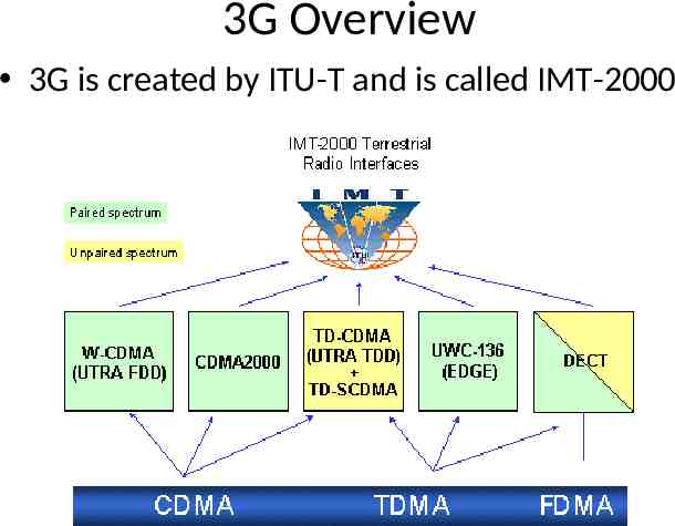
3G Overview 3G is created by ITU-T and is called IMT-2000
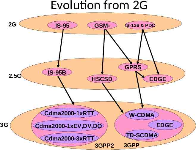
Evolution from 2G 2G 2.5G IS-95 GSM- GPRS IS-95B HSCSD Cdma2000-1xRTT 3G IS-136 & PDC EDGE W-CDMA EDGE Cdma2000-1xEV,DV,DO TD-SCDMA Cdma2000-3xRTT 3GPP2 3GPP
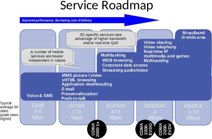
Service Roadmap Improved performance, decreasing cost of delivery Broadband in wide area 3G-specific 3G-specific services services take take advantage of higher bandwidth advantage of higher bandwidth and/or and/or real-time real-time QoS QoS Video sharing Video telephony Real-time IP AA number number of of mobile mobile Multitasking services multimedia and games services are are bearer bearer independent WEB browsing Multicasting independent in in nature nature Corporate data access Streaming audio/video MMS picture / video xHTML browsing Application downloading E-mail Presence/location Voice & SMS Push-to-talk EGPRS 473 kbps WCDMA 2 Mbps CDMA 2000EVDV GPRS 171 kbps CDMA 2000EVDO GSM 9.6 kbps CDMA 2000 1x Typical average bit rates (peak rates higher) HSDPA 1-10 Mbps
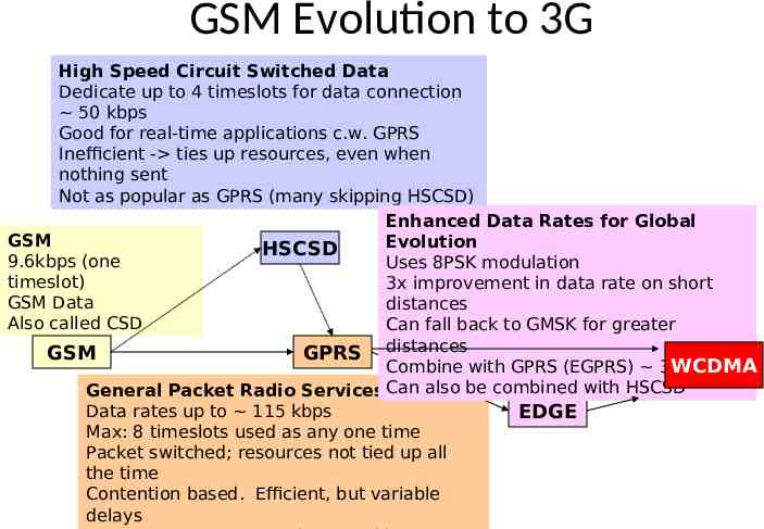
GSM Evolution to 3G High Speed Circuit Switched Data Dedicate up to 4 timeslots for data connection 50 kbps Good for real-time applications c.w. GPRS Inefficient - ties up resources, even when nothing sent Not as popular as GPRS (many skipping HSCSD) Enhanced Data Rates for Global GSM Evolution HSCSD 9.6kbps (one Uses 8PSK modulation timeslot) 3x improvement in data rate on short GSM Data distances Also called CSD Can fall back to GMSK for greater GSM GPRS distances Combine with GPRS (EGPRS) 384 kbps WCDMA General Packet Radio Services Can also be combined with HSCSD Data rates up to 115 kbps EDGE Max: 8 timeslots used as any one time Packet switched; resources not tied up all the time Contention based. Efficient, but variable delays
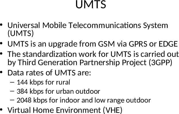
UMTS Universal Mobile Telecommunications System (UMTS) UMTS is an upgrade from GSM via GPRS or EDGE The standardization work for UMTS is carried out by Third Generation Partnership Project (3GPP) Data rates of UMTS are: – 144 kbps for rural – 384 kbps for urban outdoor – 2048 kbps for indoor and low range outdoor Virtual Home Environment (VHE)
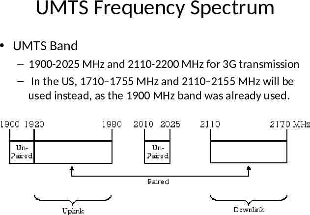
UMTS Frequency Spectrum UMTS Band – 1900-2025 MHz and 2110-2200 MHz for 3G transmission – In the US, 1710–1755 MHz and 2110–2155 MHz will be used instead, as the 1900 MHz band was already used.
UMTS Architecture Mobile Station ME SIM Base Station Subsystem BTS BSC Network Subsystem MSC/ VLR EIR Other Networks GMSC HLR PSTN AUC PLMN RNS ME USIM SD Node B RNC SGSN GGSN Internet UTRAN Note: Interfaces have been omitted for clarity purposes.
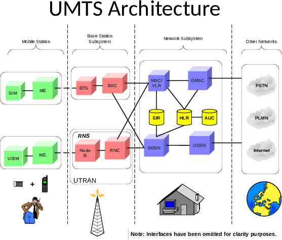
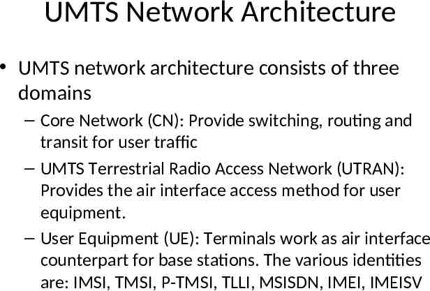
UMTS Network Architecture UMTS network architecture consists of three domains – Core Network (CN): Provide switching, routing and transit for user traffic – UMTS Terrestrial Radio Access Network (UTRAN): Provides the air interface access method for user equipment. – User Equipment (UE): Terminals work as air interface counterpart for base stations. The various identities are: IMSI, TMSI, P-TMSI, TLLI, MSISDN, IMEI, IMEISV
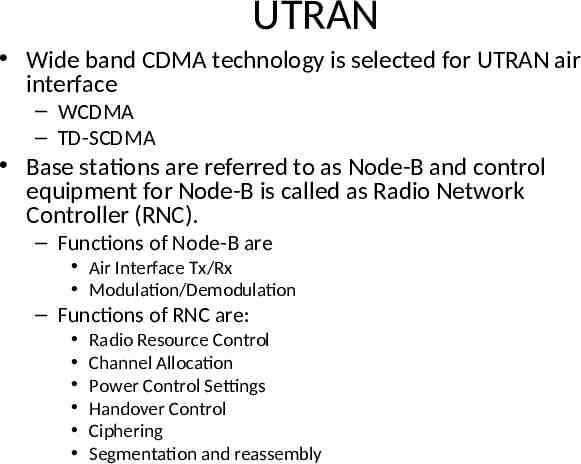
UTRAN Wide band CDMA technology is selected for UTRAN air interface – WCDMA – TD-SCDMA Base stations are referred to as Node-B and control equipment for Node-B is called as Radio Network Controller (RNC). – Functions of Node-B are Air Interface Tx/Rx Modulation/Demodulation – Functions of RNC are: Radio Resource Control Channel Allocation Power Control Settings Handover Control Ciphering Segmentation and reassembly
3.5G (HSPA) High Speed Packet Access (HSPA) is an amalgamation of two mobile telephony protocols, High Speed Downlink Packet Access (HSDPA) and High Speed Uplink Packet Access (HSUPA), that extends and improves the performance of existing WCDMA protocols 3.5G introduces many new features that will enhance the UMTS technology in future. 1xEV-DV already supports most of the features that will be provided in 3.5G. These include: - Adaptive Modulation and Coding - Fast Scheduling - Backward compatibility with 3G - Enhanced Air Interface
4G (LTE) LTE stands for Long Term Evolution Next Generation mobile broadband technology Promises data transfer rates of 100 Mbps Based on UMTS 3G technology Optimized for All-IP traffic
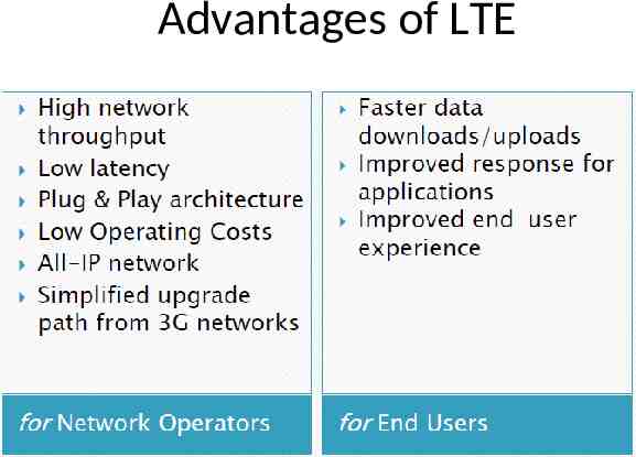
Advantages of LTE
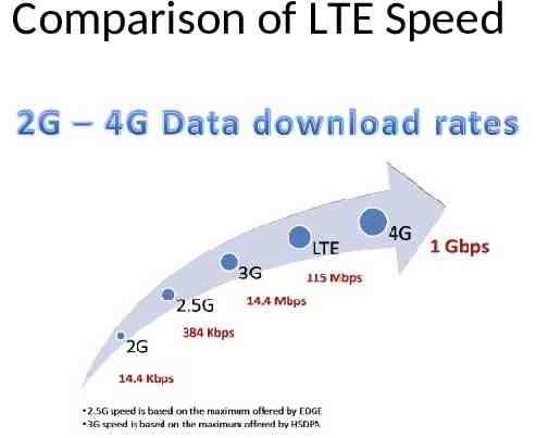
Comparison of LTE Speed
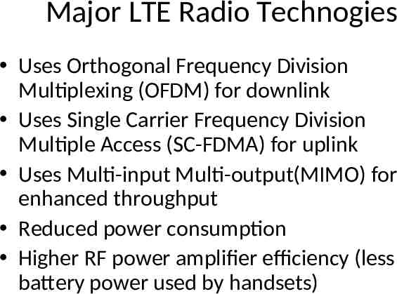
Major LTE Radio Technogies Uses Orthogonal Frequency Division Multiplexing (OFDM) for downlink Uses Single Carrier Frequency Division Multiple Access (SC-FDMA) for uplink Uses Multi-input Multi-output(MIMO) for enhanced throughput Reduced power consumption Higher RF power amplifier efficiency (less battery power used by handsets)
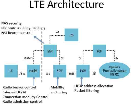
LTE Architecture
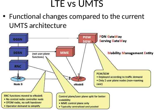
LTE vs UMTS Functional changes compared to the current UMTS architecture
Case Study Mobility: A Double-Edged Sword for HSPA Networks Fung Po Tso, City University of Hong Kong Jin Teng, Ohio State University Weijia Jia, City University of Hong Kong Dong Xuan, Ohio State University ACM Mobihoc’10
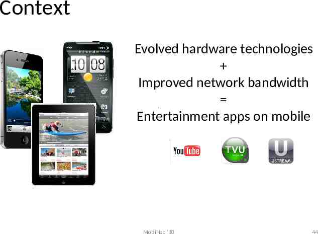
Context Evolved hardware technologies Improved network bandwidth Entertainment apps on mobile MobiHoc '10 44
Context When you are NOT mobile, you use MobiHoc '10 45
Context When you are mobile, you use MobiHoc '10 46
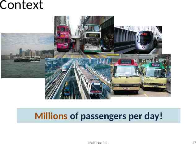
Context Millions of passengers per day! MobiHoc '10 47
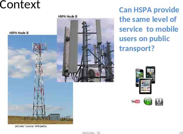
Context Can HSPA provide the same level of service to mobile users on public transport? HSPA Node B HSPA Node B pictures’ source: Wikipedia MobiHoc '10 48
Outline Measurement Methodology General Impact of Mobility Mobility Impact on Bandwidth Sharing Mobility Impact in Transitional Region Conclusion MobiHoc '10 49
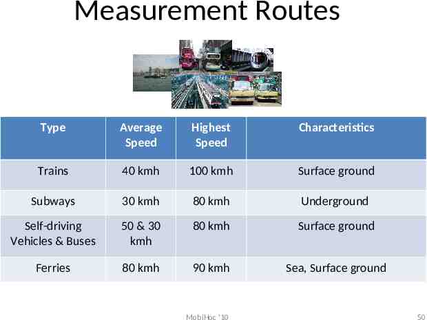
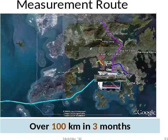
Measurement Routes Type Average Speed Highest Speed Characteristics Trains 40 kmh 100 kmh Surface ground Subways 30 kmh 80 kmh Underground Self-driving Vehicles & Buses 50 & 30 kmh 80 kmh Surface ground Ferries 80 kmh 90 kmh Sea, Surface ground MobiHoc '10 50
Measurement Route Over 100 km in 3 months MobiHoc '10 51
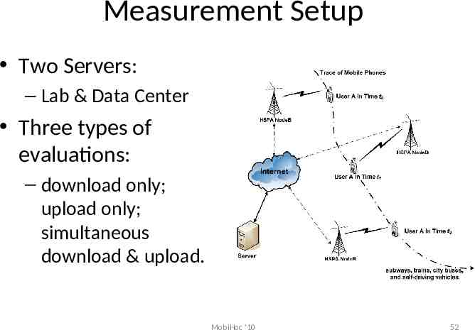
Measurement Setup Two Servers: – Lab & Data Center Three types of evaluations: – download only; upload only; simultaneous download & upload. MobiHoc '10 52
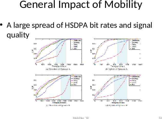
General Impact of Mobility A large spread of HSDPA bit rates and signal quality MobiHoc '10 53
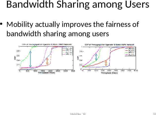
Context Common View: Mobility is irrelevant, if not detrimental, to the fairness in HSPA bandwidth sharing among users Observation: The bandwidth sharing practice in stationary HSPA environments is unfair. In contrast, mobility surprisingly improves fairness of bandwidth sharing (fairer). MobiHoc '10 54
Bandwidth Sharing among Users Mobility actually improves the fairness of bandwidth sharing among users MobiHoc '10 55
Bandwidth Sharing among Users UE can hardly keep its dominancy under rapid change of radio environment. – Mobile nodes may see better signal quality at new locations Cell to cell based scheduling algorithm prevent unfairness from propagating MobiHoc '10 56
Context Common View: Mobility affects all flows equally. And TCP flows suffer more than UDP ones Observation: TCP flows unexpectedly see much better performance during mobility than UDP flows. MobiHoc '10 57
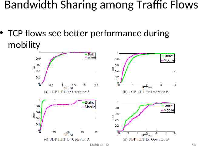
Bandwidth Sharing among Traffic Flows TCP flows see better performance during mobility MobiHoc '10 58
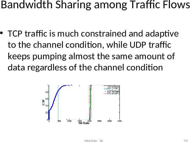
Bandwidth Sharing among Traffic Flows TCP traffic is much constrained and adaptive to the channel condition, while UDP traffic keeps pumping almost the same amount of data regardless of the channel condition MobiHoc '10 59
Context Common View: Handoffs are triggered in the transitional region between cells and always result in a better wireless connection Observation: Nearly 30% of all handoffs, selection of a base station with poorer signal quality can be witnessed MobiHoc '10 60
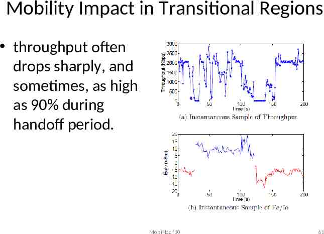
Mobility Impact in Transitional Regions throughput often drops sharply, and sometimes, as high as 90% during handoff period. MobiHoc '10 61
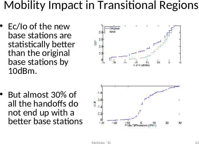
Mobility Impact in Transitional Regions Ec/Io of the new base stations are statistically better than the original base stations by 10dBm. But almost 30% of all the handoffs do not end up with a better base stations MobiHoc '10 62
Conclusion Mobility is a double edged sword – Degrades HSPA services, e.g. throughput – Improves fairness in bandwidth allocation among users and traffic flows Communication characteristics in HSPA transitional regions are very complicated MobiHoc '10 63
Acknowledgement Part of the slides are adapted from the slides of Posco Tso, Harish Vishwanath, Erran Li and Justino Lorenco, Saro Velrajan and TCL India