INFO 2950 Prof. Carla Gomes [email protected] Module Modeling
29 Slides775.00 KB
INFO 2950 Prof. Carla Gomes [email protected] Module Modeling Computation: Finite State Machines with Output Rosen, Chapter 12.2 1
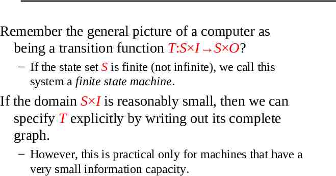
Remember the general picture of a computer as being a transition function T:S I S O? – If the state set S is finite (not infinite), we call this system a finite state machine. If the domain S I is reasonably small, then we can specify T explicitly by writing out its complete graph. – However, this is practical only for machines that have a very small information capacity.
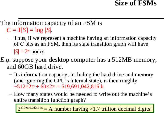
Size of FSMs The information capacity of an FSM is C I[S] log S . – Thus, if we represent a machine having an information capacity of C bits as an FSM, then its state transition graph will have S 2C nodes. E.g. suppose your desktop computer has a 512MB memory, and 60GB hard drive. – Its information capacity, including the hard drive and memory (and ignoring the CPU’s internal state), is then roughly 512 223 60 233 519,691,042,816 b. – How many states would be needed to write out the machine’s entire transition function graph? 2519,691,042,816 A number having 1.7 trillion decimal digits!
FSMs as Models The FSM diagram of a reasonably-sized computer is more than astronomically huge. – Yet, we are able to design and build these computers using only a modest amount of industrial resources. Why is this possible? Answer: A real computer has regularities in its transition function that are not captured if we just write out its FSM transition function explicitly. – I.e., a transition function can have a small, simple, regular description, even if its domain is enormous.
Limitations with FSM Model It ignores many important physical realities: – How is the transition function’s structure to be encoded in physical hardware? How much hardware complexity is required to do this? – How close in physical space is one bit’s worth of the machine’s information capacity to another? How long does it take to communicate information from one part of the machine to another? – How much energy gets dissipated to heat when the machine updates its state? How fast can the heat be removed, and how much does this impact the machine’s performance? Let’s consider a basic example.
Applications Finite-State Machines are used in a variety of applications. – – – – – Spell checking programs Grammar checking Indexing and searching large text files Speech/Language recognition Network Protocols
Types of Finite-State Machines Finite-State Machines with Output – Mealy: Output determined by state and input – Moore: Output determined by state alone Finite-State Machines with No Output – Also known as finite-state automata – There are two types of finite-state automata Deterministic: Each state-input pair dictates a unique transition into another state Non-deterministic: Each state-input pair can lead to several possible states
Finite State Machines with Output We will focus on only Mealy machines Since we will always refer to finite-state machines with no output as finite-state automata, we will use the term finite-state machine to mean finitestate machine with output. The best way to understand finite-state machines is probably with an example. Perhaps the best example deals with a device most of use are very familiar with—vending machines.
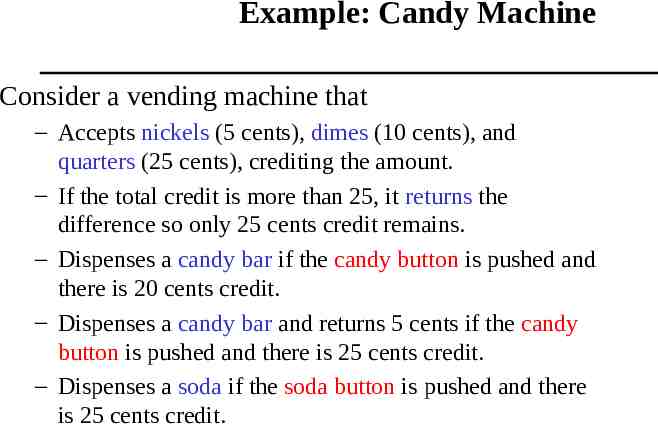
Example: Candy Machine Consider a vending machine that – Accepts nickels (5 cents), dimes (10 cents), and quarters (25 cents), crediting the amount. – If the total credit is more than 25, it returns the difference so only 25 cents credit remains. – Dispenses a candy bar if the candy button is pushed and there is 20 cents credit. – Dispenses a candy bar and returns 5 cents if the candy button is pushed and there is 25 cents credit. – Dispenses a soda if the soda button is pushed and there is 25 cents credit.
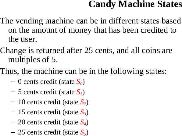
Candy Machine States The vending machine can be in different states based on the amount of money that has been credited to the user. Change is returned after 25 cents, and all coins are multiples of 5. Thus, the machine can be in the following states: – – – – – – 0 cents credit (state S0) 5 cents credit (state S1) 10 cents credit (state S2) 15 cents credit (state S3) 20 cents credit (state S4) 25 cents credit (state S5)
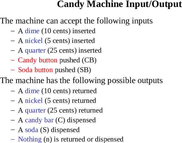
Candy Machine Input/Output The machine can accept the following inputs – – – – – A dime (10 cents) inserted A nickel (5 cents) inserted A quarter (25 cents) inserted Candy button pushed (CB) Soda button pushed (SB) The machine has the following possible outputs – – – – – – A dime (10 cents) returned A nickel (5 cents) returned A quarter (25 cents) returned A candy bar (C) dispensed A soda (S) dispensed Nothing (n) is returned or dispensed
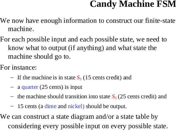
Candy Machine FSM We now have enough information to construct our finite-state machine. For each possible input and each possible state, we need to know what to output (if anything) and what state the machine should go to. For instance: – If the machine is in state S3 (15 cents credit) and – a quarter (25 cents) is input – the machine should transition into state S5 (25 cents credit) and – 15 cents (a dime and nickel) should be output. We can construct a state diagram and/or a state table by considering every possible input on every possible state.
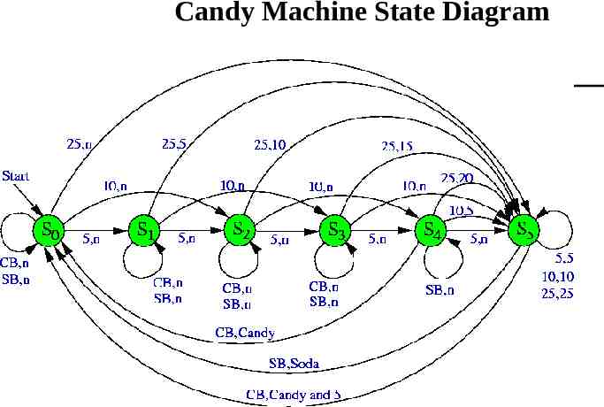
Candy Machine State Diagram
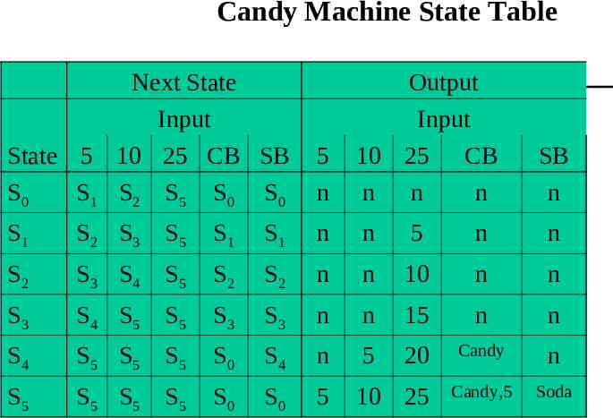
Candy Machine State Table Next State Input State 5 10 25 CB SB S0 S 1 S2 S 5 S 0 S 0 5 n Output Input 10 25 CB n n n S1 S 2 S3 S 5 S1 S1 n n 5 n n S2 S 3 S4 S 5 S2 S2 n n 10 n n S3 S 4 S5 S 5 S3 S3 n n 15 n n S4 S 5 S5 S 5 S0 S4 n 5 20 Candy n S5 S 5 S5 S 5 S0 S0 5 10 25 Candy,5 Soda SB n
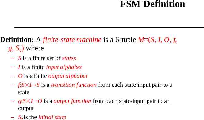
FSM Definition Definition: A finite-state machine is a 6-tuple M (S, I, O, f, g, S0) where – – – – S is a finite set of states I is a finite input alphabet O is a finite output alphabet f:S I S is a transition function from each state-input pair to a state – g:S I O is a output function from each state-input pair to an output – S0 is the initial state
FSM Representations As we have already seen, there are two common ways of representing finite-state machines – A state table is used to represent a finite-state machine by giving the values of the functions f and g. – A state diagram is a directed graph representation of a finite-state machine.
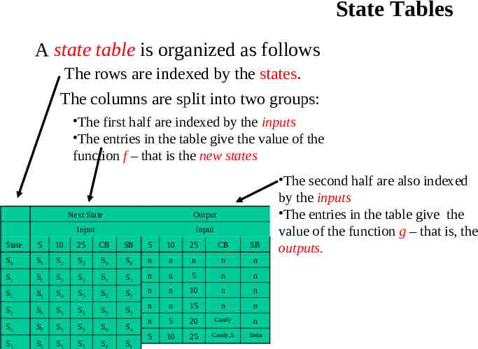
State Tables A state table is organized as follows The rows are indexed by the states. The columns are split into two groups: The first half are indexed by the inputs The entries in the table give the value of the function f – that is the new states Next State Output Input Input State 5 10 25 CB SB 5 10 25 CB SB S0 S1 S2 S5 S0 S0 n n n n n S1 S2 S3 S5 S1 S1 n n 5 n n S2 S3 S4 S5 S2 S2 n n 10 n n S3 S4 S5 S5 S3 S3 n n 15 n n S4 S5 S5 S5 S0 S4 n 5 20 Candy n S5 S5 S0 S0 10 25 Soda S5 5 Candy,5 S5 The second half are also indexed by the inputs The entries in the table give the value of the function g – that is, the outputs.
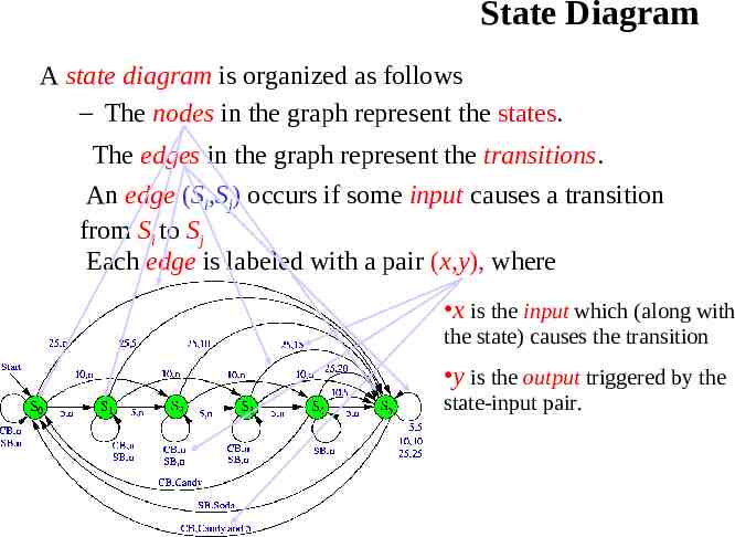
State Diagram A state diagram is organized as follows – The nodes in the graph represent the states. The edges in the graph represent the transitions. An edge (Si,Sj) occurs if some input causes a transition from Si to Sj Each edge is labeled with a pair (x,y), where x is the input which (along with the state) causes the transition y is the output triggered by the state-input pair.
Example: Unit Delay In some electronic devices, it is necessary to use a unit-delay machine. That is, whatever is input into the machine should be output from the machine, but delayed by a specific amount of time. For instance, given a string of binary numbers x1, x2, , xn, the machine should produce the string 0,x1, x2, , xn-1. We want to use a finite state machine to model the behavior of a unit-delay machine. What should a state in this machine represent? One possibility is that a state represents the last input bit. Thus we need a state for “1” and a state for “0” We also need start state.
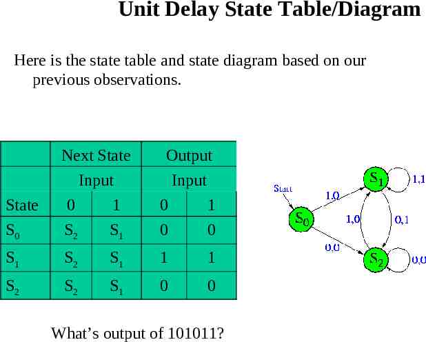
Unit Delay States We will use the following states (that memorize last bit; except S0) – State S0 is the start state – State S1 occurs if the previous input was 1 – State S2 occurs if the previous input was 0 We can easily construct the state table for the unit delay machine by realizing that – When the input is 0, we always transition to state S2 – When the input is 1, we always transition to state S1 – When we are in state S1 we always output 1 (since the previous input was 1) – When we are in state S2 we always output 0 (since the previous input was 0) – When we are in state S0 we always output 0 (since we always output 0 first)
Unit Delay State Table/Diagram Here is the state table and state diagram based on our previous observations. Next State Output Input Input State 0 1 0 1 S0 S2 S1 0 0 S1 S2 S1 1 1 S2 S2 S1 0 0 What’s output of 101011?
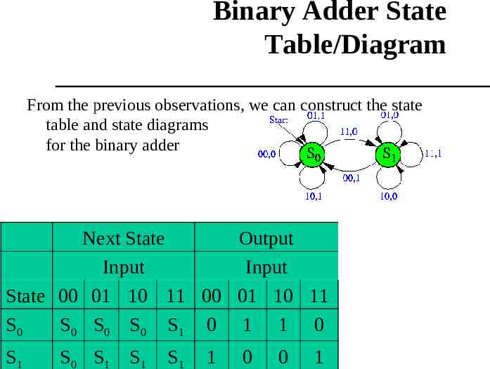
Example: Binary Adder We want to construct a finite state machine that will add two numbers. The input is two binary numbers, (xn x1x0)2 and (yn y1y0)2 At each step, we can compute (xi yi) starting with (x0 y0). – If (xi yi) 0, we output 0. – If (xi yi) 1, we output 1. – If (xi yi) 2, we have a problem. The problem is we need a carry bit. In fact, our computation needs to know the carry bit at each step (so we compute xi yi ci at each step), and be able to give it to the next step. We can take care of this by using states to represent the carry bit.
Binary Adder States We will use the following states – State S0 occurs if the carry bit is 0 – State S1 occurs if the carry bit is 1 Since when we begin the computation, there is no carry, we can use S0 as the start state, So, how does which state we are in affect the output? If we are in state S0 (we have a carry of 0) – If (xi yi) 0, we output 0, and stay in state S0 – If (xi yi) 1, we output 1, and stay in state S0 – If (xi yi) 2, we output 0, and go to state S1 If we are in state S1 (we have a carry of 1) – If (xi yi 1) 1, we output 1, and go to state S0 – If (xi yi 1) 2, we output 0, and stay in state S1 – If (xi yi 1) 3, we output 1, and stay in state S1
Binary Adder State Table/Diagram From the previous observations, we can construct the state table and state diagrams for the binary adder Next State Output Input Input State 00 01 10 11 00 01 10 11 S0 S0 S 0 S0 S1 0 1 1 0 S1 S0 S 1 S1 S1 1 0 0 1
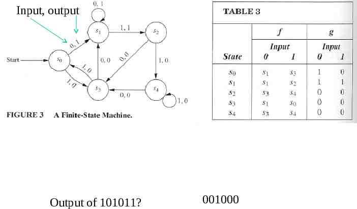
Construct a state table for the finite-state machine in Fig. 3. Input, output Find the output string for the input 101011 Answer: 001000 Output of 101011? 001000
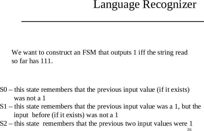
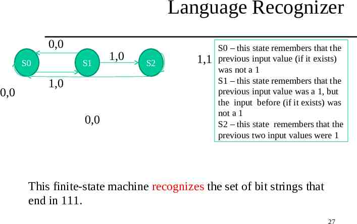
Language Recognizer We want to construct an FSM that outputs 1 iff the string read so far has 111. S0 – this state remembers that the previous input value (if it exists) was not a 1 S1 – this state remembers that the previous input value was a 1, but the input before (if it exists) was not a 1 S2 – this state remembers that the previous two input values were 1 26
Language Recognizer 0,0 S0 0,0 S1 1,0 0,0 1,0 S2 1,1 S0 – this state remembers that the previous input value (if it exists) was not a 1 S1 – this state remembers that the previous input value was a 1, but the input before (if it exists) was not a 1 S2 – this state remembers that the previous two input values were 1 This finite-state machine recognizes the set of bit strings that end in 111. 27
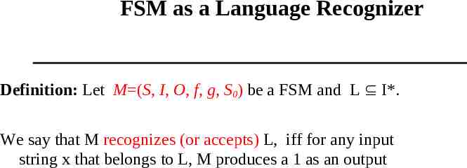
FSM as a Language Recognizer Definition: Let M (S, I, O, f, g, S0) be a FSM and L I*. We say that M recognizes (or accepts) L, iff for any input string x that belongs to L, M produces a 1 as an output
Next Finite state machines with no output Finite Automata 29