IAEA Regional Training Course on Radiation Protection of patients for
44 Slides3.37 MB
IAEA Regional Training Course on Radiation Protection of patients for Radiographers, Accra, Ghana, 11-15 July 2011 Optimization of Protection in Computed Tomography (CT)-What can radiographers do? IAEA IAEA International Atomic Energy Agency
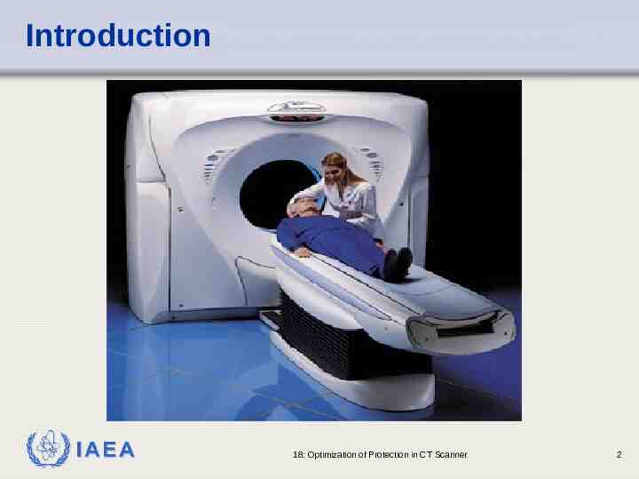
Introduction IAEA 18: Optimization of Protection in CT Scanner 2
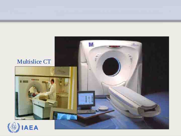
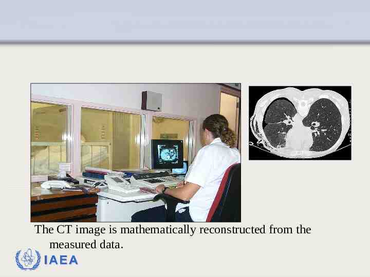
Multislice CT scanner IAEA
The CT image is mathematically reconstructed from the measured data. IAEA
Outline Introduction Factors affecting image quality Factors affecting dose Optimization IAEA 18: Optimization of Protection in CT Scanner 5
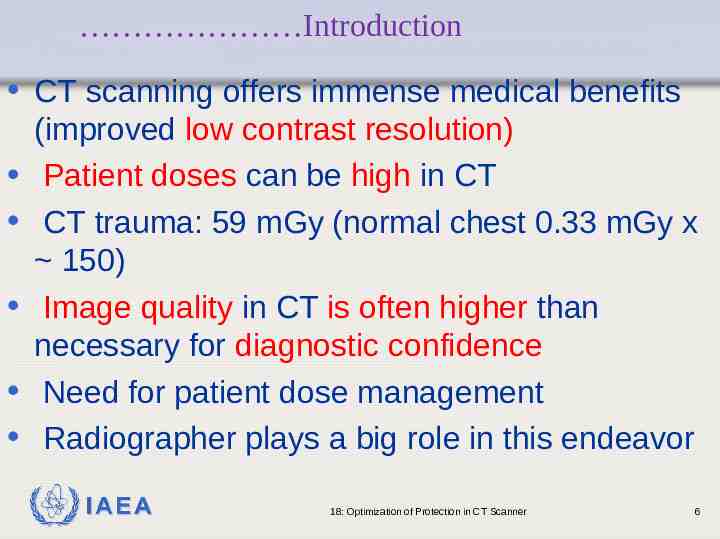
Introduction CT scanning offers immense medical benefits (improved low contrast resolution) Patient doses can be high in CT CT trauma: 59 mGy (normal chest 0.33 mGy x 150) Image quality in CT is often higher than necessary for diagnostic confidence Need for patient dose management Radiographer plays a big role in this endeavor IAEA 18: Optimization of Protection in CT Scanner 6
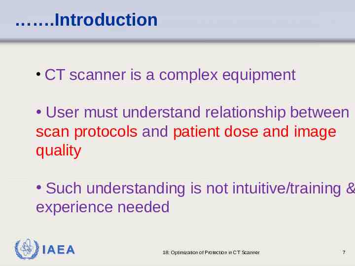
.Introduction CT scanner is a complex equipment User must understand relationship between scan protocols and patient dose and image quality Such understanding is not intuitive/training & experience needed IAEA 18: Optimization of Protection in CT Scanner 7
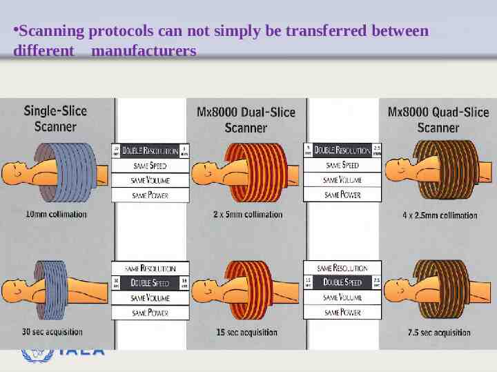
Scanning protocols can not simply be transferred between different manufacturers IAEA
Factors affecting image quality Spatial resolution Contrast discrimination Spatial uniformity Noise Pixel size Slice thickness mAs Tube voltage Reconstruction algorithm Sampling frequency Pitch (in multislice) Patient size IAEA 18: Optimization of Protection in CT Scanner 9
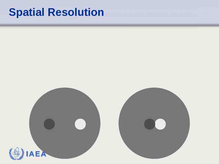
Spatial resolution The ability to resolve neighbouring structures Size of detectors Number of detectors X-ray focus Distance between source and detector Sampling frequency IAEA 18: Optimization of Protection in CT Scanner 10
Spatial Resolution IAEA
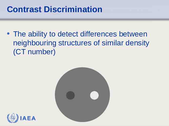
Contrast Discrimination The ability to detect differences between neighbouring structures of similar density (CT number) IAEA
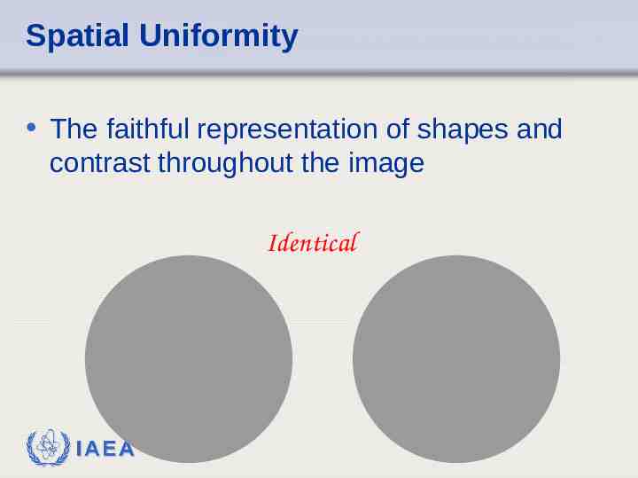
Spatial Uniformity The faithful representation of shapes and contrast throughout the image Identical IAEA
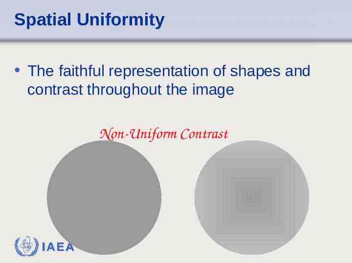
Spatial Uniformity The faithful representation of shapes and contrast throughout the image Non-Uniform Contrast IAEA
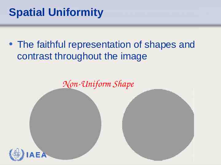
Spatial Uniformity The faithful representation of shapes and contrast throughout the image Non-Uniform Shape IAEA
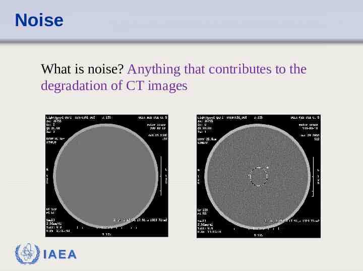
Noise What is noise? Anything that contributes to the degradation of CT images IAEA
Noise Decreases the quality of the image Makes diagnosis harder by Masking information Not presenting correct information IAEA
Other Factors - Image Quality & Patient Dose Pixel Size Slice Thickness mAs Algorithm Sampling Frequency Artefacts IAEA
Slice Thickness Thin slice - smaller signal Smaller signal - more noise More noise - poor image Solution increase dose!! IAEA
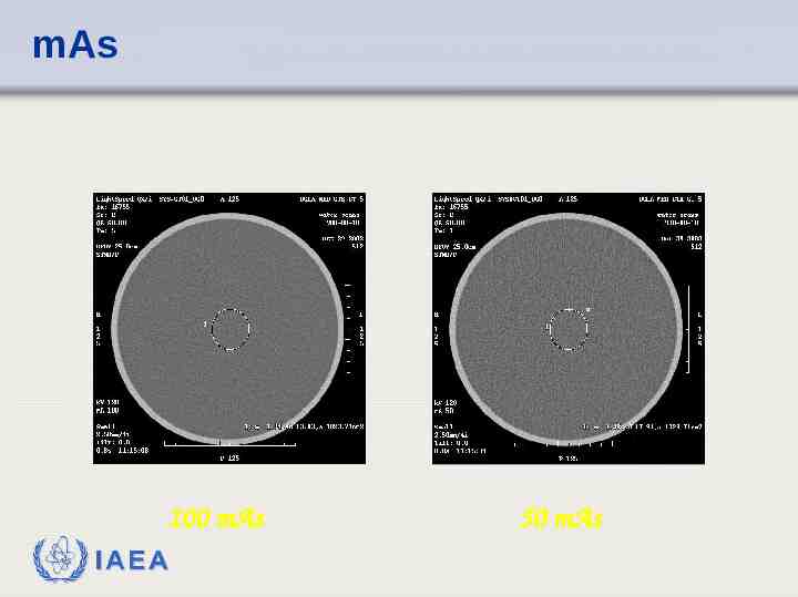
mAs Current directly proportional to intensity of X rays Low current, low intensity Low intensity, low signal Low quality image produced Solution increase dose!! IAEA
mAs 100 mAs IAEA 50 mAs
Paper of Interest http://www.oucom.ohiou.edu/ou-microct/Dow nloads/Tradeoffs in CT Image Quality an d Dose 9794-13379.pdf Good paper on CT image quality & dose tradeoffs IAEA
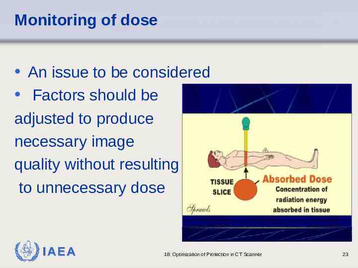
Monitoring of dose An issue to be considered Factors should be adjusted to produce necessary image quality without resulting to unnecessary dose IAEA 18: Optimization of Protection in CT Scanner 23
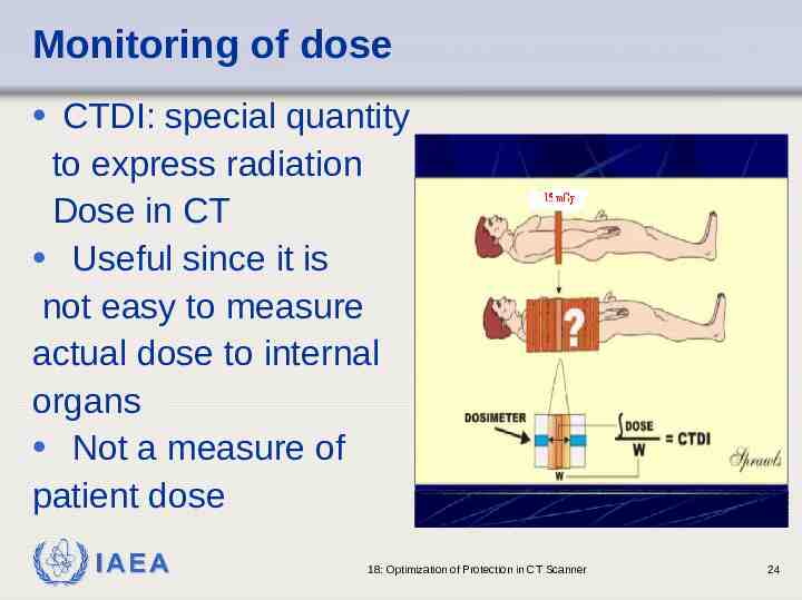
Monitoring of dose CTDI: special quantity to express radiation Dose in CT Useful since it is not easy to measure actual dose to internal organs Not a measure of patient dose IAEA 18: Optimization of Protection in CT Scanner 24
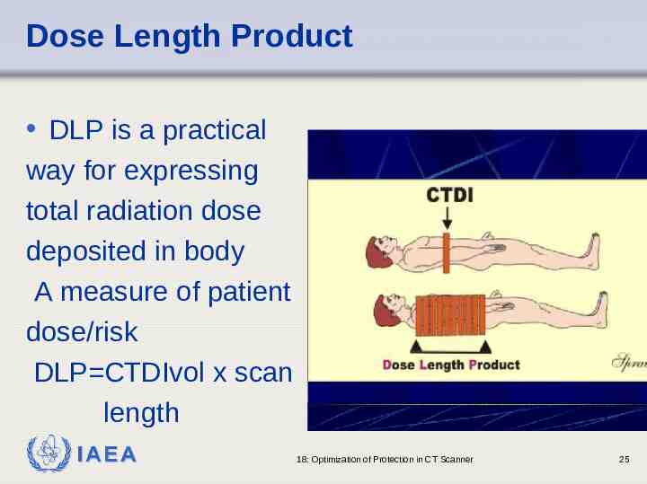
Dose Length Product DLP is a practical way for expressing total radiation dose deposited in body A measure of patient dose/risk DLP CTDIvol x scan length IAEA 18: Optimization of Protection in CT Scanner 25
Factors affecting dose Tube current (mA) Scan (rotation) time (s) Tube voltage Beam (slice) width (mm) Helical pitch Number of slices/tube rotations Number of slices/tube rotations IAEA 18: Optimization of Protection in CT Scanner 26
Effect of scan parameters on CTDIvol mAs and scan (rotation) time -At a given pitch, CTDIvol increases linearly with mA and time e.g. 2 x mAs 2x CTDIvol - Given 100 mA 1s, one can double mAs by 200 mA x 1s or 100 mA x 2s) IAEA 18: Optimization of Protection in CT Scanner 27
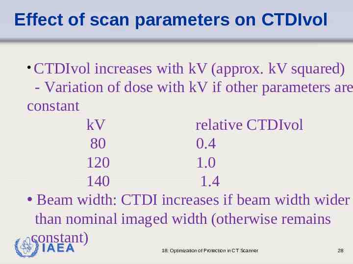
Effect of scan parameters on CTDIvol CTDIvol increases with kV (approx. kV squared) - Variation of dose with kV if other parameters are constant kV relative CTDIvol 80 0.4 120 1.0 140 1.4 Beam width: CTDI increases if beam width wider than nominal imaged width (otherwise remains constant) IAEA 18: Optimization of Protection in CT Scanner 28
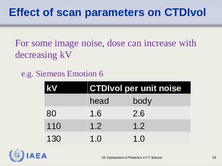
Effect of scan parameters on CTDIvol For some image noise, dose can increase with decreasing kV e.g. Siemens Emotion 6 kV 80 110 130 IAEA CTDIvol per unit noise head body 1.6 2.6 1.2 1.2 1.0 1.0 18: Optimization of Protection in CT Scanner 29
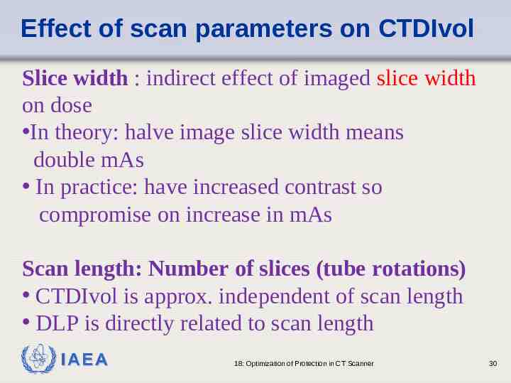
Effect of scan parameters on CTDIvol Slice width : indirect effect of imaged slice width on dose In theory: halve image slice width means double mAs In practice: have increased contrast so compromise on increase in mAs Scan length: Number of slices (tube rotations) CTDIvol is approx. independent of scan length DLP is directly related to scan length IAEA 18: Optimization of Protection in CT Scanner 30
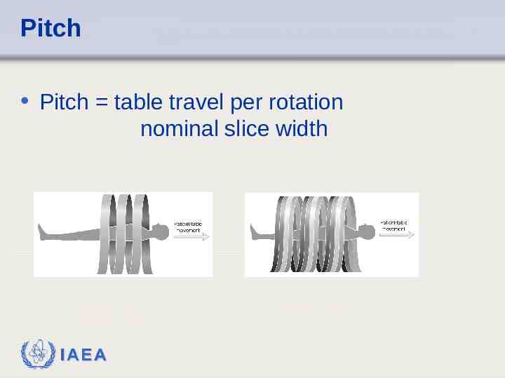
Pitch Pitch table travel per rotation nominal slice width Single Slice IAEA Multi Slice
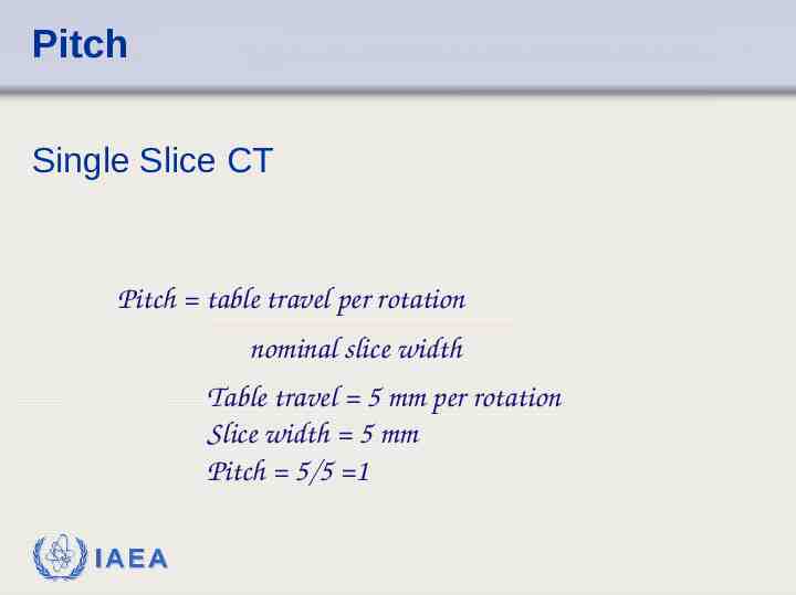
Pitch Single Slice CT Pitch table travel per rotation nominal slice width Table travel 5 mm per rotation Slice width 5 mm Pitch 5/5 1 IAEA
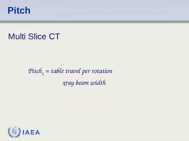
Pitch Multi Slice CT Pitchx table travel per rotation xray beam width IAEA
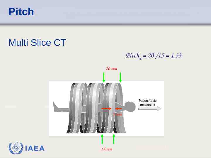
Pitch Multi Slice CT Pitchx 20 /15 1.33 20 mm 5 mm IAEA 15 mm Pitchd 20 / 5 4
Pitch Pitch 1, no gaps in helical path Pitch 1, gaps Pitch 1, overlap IAEA
Helical considerations For equivalent scan parameters: helical dose is approx.equal to sequential (axial dose) For constant mAs, CTDIvol is inversely proportional to pitch On single slice scanners, increasing pitch is used for dose reduction) IAEA 18: Optimization of Protection in CT Scanner 36
Multi-slice considerations Dose differences between single and multi-slice - Use of pitch for dose reduction - Extent of additional rotations in helical scanning -’over-beaming’-penumbra lies outside active detectors Multi-slice pitch: 200 mAs (200 mA, 1s rotation) Effective mAs or mAs per slice True mAs/ pitch On MSCT, mAs is often adjusted to keep effective mAs constant Therefore CTDIvol will remain constant with pitch IAEA 18: Optimization of Protection in CT Scanner 37
Multislice: scan protocol Greater flexibility of MSCT allows user to - increase scan length - scan more phases in multiphase studies - increase mAs to keep noise down in thin slices IAEA 18: Optimization of Protection in CT Scanner 38
Effect of patient size Theory of x-ray CT: HVL in tissue is approx. 4 cm To maintain constant noise, double mAs for extra 4 cm of tissue Adjusting mAs for patient size: - small patients: require lower noise -large patients : higher noise accepted Some manufacturers recommend doubling mAs for - approx. 10 cm in abdomen scans -approx. 13 cm in lung scans Automatic tube current control (mA modulation) (20-50% dose reductions without compromising image quality) -manufacturer’s weight/age based pre-programmed protocol - mAs adjusted for lateral patient dimensions IAEA 18: Optimization of Protection in CT Scanner 39
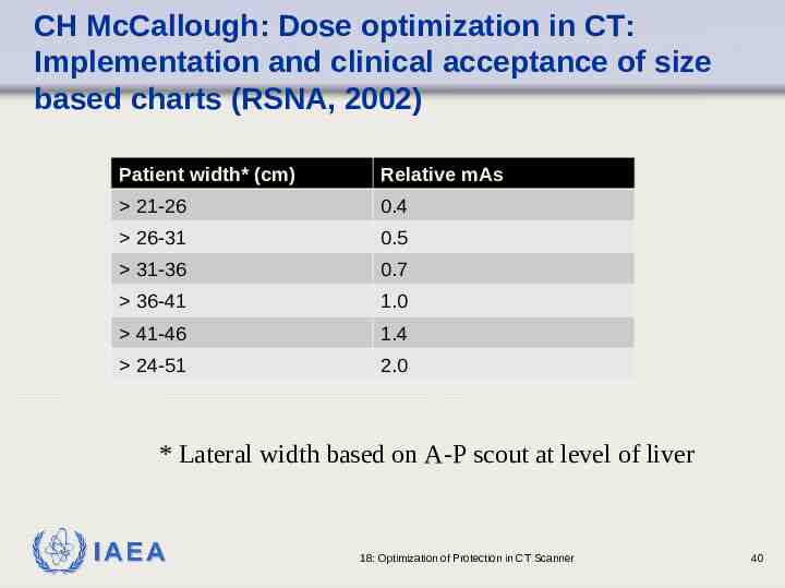
CH McCallough: Dose optimization in CT: Implementation and clinical acceptance of size based charts (RSNA, 2002) Patient width* (cm) Relative mAs 21-26 0.4 26-31 0.5 31-36 0.7 36-41 1.0 41-46 1.4 24-51 2.0 * Lateral width based on A-P scout at level of liver IAEA 18: Optimization of Protection in CT Scanner 40
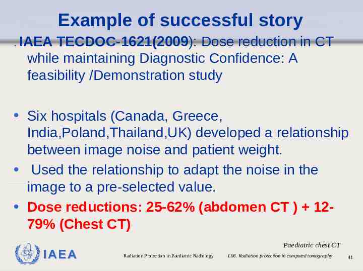
Example of successful story . IAEA TECDOC-1621(2009): Dose reduction in CT while maintaining Diagnostic Confidence: A feasibility /Demonstration study Six hospitals (Canada, Greece, India,Poland,Thailand,UK) developed a relationship between image noise and patient weight. Used the relationship to adapt the noise in the image to a pre-selected value. Dose reductions: 25-62% (abdomen CT ) 1279% (Chest CT) IAEA Paediatric chest CT Radiation Protection in Paediatric Radiology L06. Radiation protection in computed tomography 41
Quality Control Tests In CT Quality control test description on: CT accuracy, uniformity, linearity and noise, Low and high contrast resolution Alignment, Couch travel accuracy Gantry tilt measurement Dosimetry IAEA 18: Optimization of protection in CT scanner 42
Summary Scanning parameters should be based on study indication, patient size and body region being scanned Manufacturer protocols should be the starting point. Any adjustments must be done in consultation of radiologist. Image quality in CT is often higher than necessary for diagnostic confidence Implementation of QC programme is important for patient dose management Training of physicians and CT staff can help in management of protocols and patient dose IAEA 18: Optimization of Protection in CT Scanner 43
THANK YOU! IAEA 18: Optimization of Protection in CT Scanner 44