GE – ECM Motor Technology and Troubleshooting Presented by The RLCS


66 Slides4.53 MB
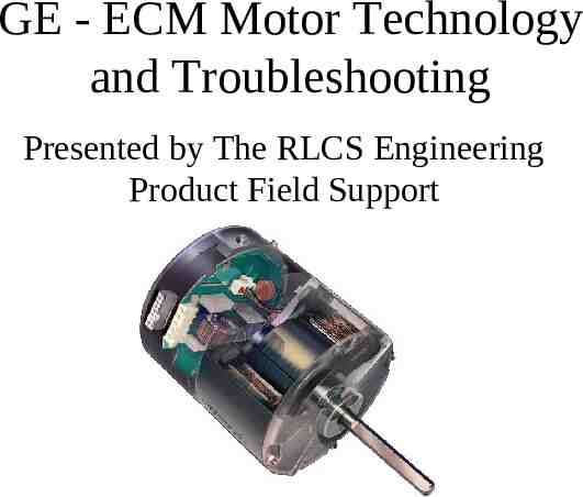
GE - ECM Motor Technology and Troubleshooting Presented by The RLCS Engineering Product Field Support
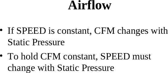
Airflow If SPEED is constant, CFM changes with Static Pressure To hold CFM constant, SPEED must change with Static Pressure
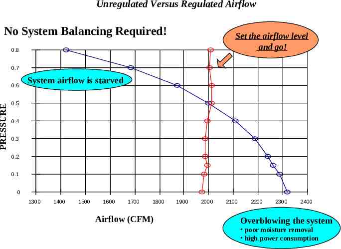
Unregulated Versus Regulated Airflow No System Balancing Required! Set the airflow level and go! 0.8 0.7 PRESSURE 0.6 System airflow is starved 0.5 0.4 0.3 0.2 0.1 0 1300 1400 1500 1600 1700 1800 Airflow (CFM) 1900 2000 2100 2200 2300 2400 Overblowing the system poor moisture removal high power consumption
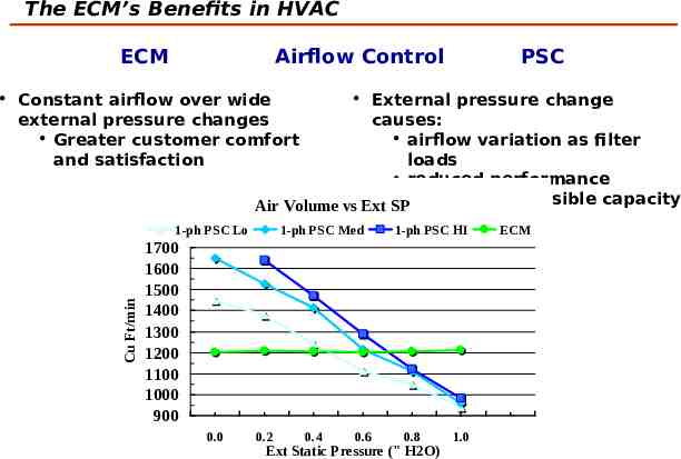
The ECM’s Benefits in HVAC ECM Airflow Control PSC Constant airflow over wide external pressure changes Greater customer comfort and satisfaction Cu Ft/min 1-ph PSC Lo External pressure change causes: airflow variation as filter loads reduced performance poor latent/sensible capacity Air Volume vs Ext SP control 1-ph PSC Med 1-ph PSC HI 1700 1600 1500 1400 1300 1200 1100 1000 900 0.0 0.2 0.4 0.6 0.8 Ext Static Pressure (" H2O) 1.0 ECM
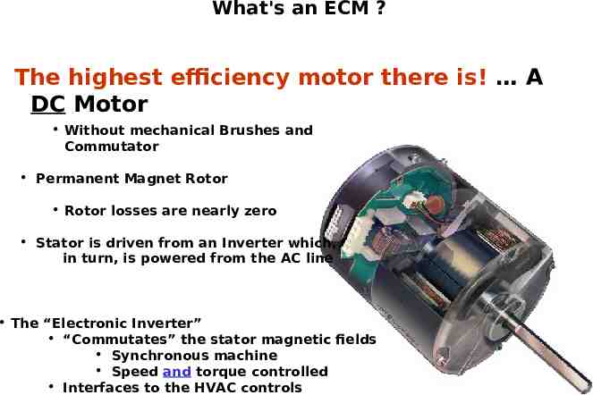
What's an ECM ? The highest efficiency motor there is! A DC Motor Without mechanical Brushes and Commutator Permanent Magnet Rotor Rotor losses are nearly zero Stator is driven from an Inverter which, in turn, is powered from the AC line The “Electronic Inverter” “Commutates” the stator magnetic fields Synchronous machine Speed and torque controlled Interfaces to the HVAC controls
ECM Issues - Furnaces / Fan coils Prior to potted controls: – Moisture was responsible for most failures The Power Transistors were the most common failure Contaminants from the air, added to the moisture/condensation, were also a concern Now, most common failure: – NO defects found
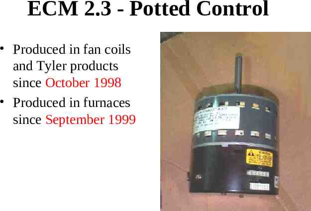
ECM 2.3 - Potted Control Produced in fan coils and Tyler products since October 1998 Produced in furnaces since September 1999
Types of ECM Control Thermostatically Controlled – Fan Coils / Non-condensing furnaces / Packaged Units Pulse Width Modulation (PWM) – Split systems (A/C & Heat Pump) – Condensing Furnaces
Thermostatically Control ECM logic for fan coils, non-condensing furnaces and Tyler products – Uses Full, Half, Positive, Negative or No Sine wave – Bases CFM on predetermined CFM curves Models programmed differently – CFM is controlled by adjusting torque in response to RPM – RPM is sensed by the motor’s “back EMF” – Always uses the “highest CFM” of what is being called for
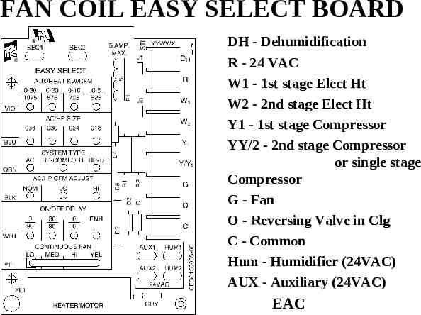
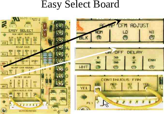
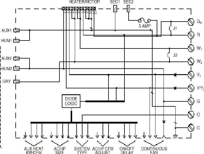
FAN COIL EASY SELECT BOARD DH - Dehumidification R - 24 VAC W1 - 1st stage Elect Ht W2 - 2nd stage Elect Ht Y1 - 1st stage Compressor YY/2 - 2nd stage Compressor or single stage Compressor G - Fan O - Reversing Valve in Clg C - Common Hum - Humidifier (24VAC) AUX - Auxiliary (24VAC) EAC
ECM Logic Pulse Width Modulation PWM
Pulse Width Modulation (PWM) PWM is a simple way of commanding airflow (CFM), as defined from an external device (2 wire method) The variable speed circuit board supplies this signal to the motors
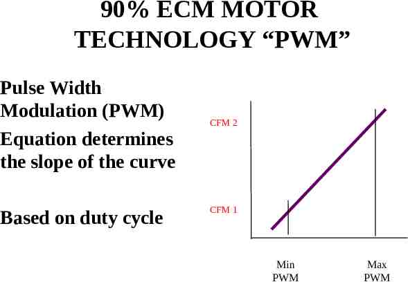
90% ECM MOTOR TECHNOLOGY “PWM” Pulse Width Modulation (PWM) Equation determines the slope of the curve Based on duty cycle CFM 2 CFM 1 Min PWM Max PWM
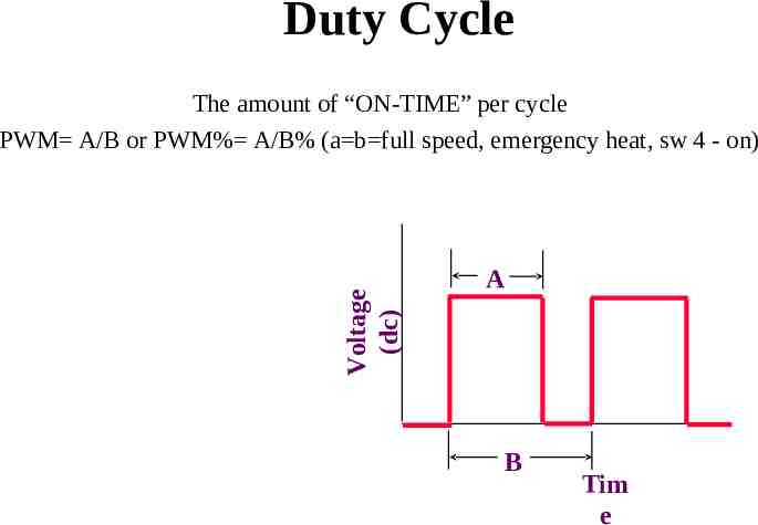
Duty Cycle Voltage (dc) The amount of “ON-TIME” per cycle PWM A/B or PWM% A/B% (a b full speed, emergency heat, sw 4 - on) A B Tim e
ECM logic for variable speed condensing gas furnaces Furnace control board sends a PWM signal to the motor Control logic is contained in the Furnace control board – Airflow is determined by the model or “personality plug” on furnace board PWM can be read by an oscilloscope – will be seen as a square waveform
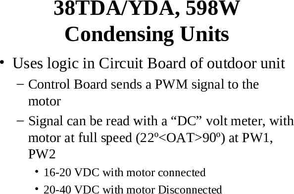
38TDA/YDA, 598W Condensing Units Uses logic in Circuit Board of outdoor unit – Control Board sends a PWM signal to the motor – Signal can be read with a “DC” volt meter, with motor at full speed (22º OAT 90º) at PW1, PW2 16-20 VDC with motor connected 20-40 VDC with motor Disconnected
Control Board Setups
FAN COIL EASY SELECT BOARD DH - Dehumidification R - 24 VAC W1 - 1st stage Elect Ht W2 - 2nd stage Elect Ht Y1 - 1st stage Compressor YY/2 - 2nd stage Compressor or single stage Compressor G - Fan O - Reversing Valve in Clg C - Common Hum - Humidifier (24VAC) AUX - Auxiliary (24VAC) EAC
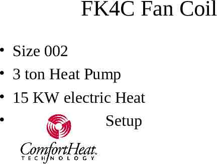
FK4C Fan Coil Size 002 3 ton Heat Pump 15 KW electric Heat Setup
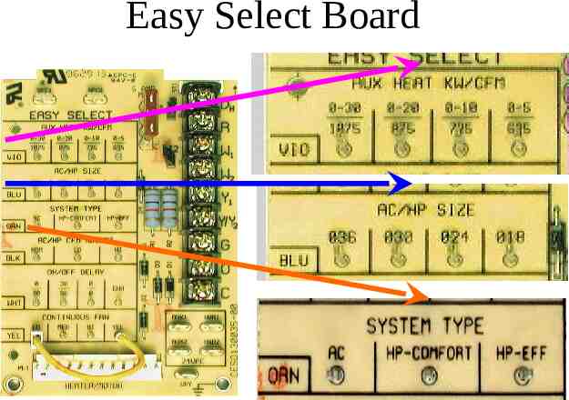
Easy Select Board
Easy Select Board HP-COMFORT LO CFM ENH DELAY
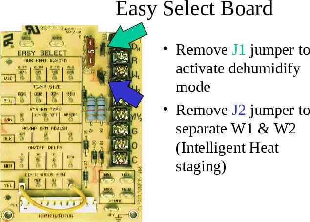
Easy Select Board Remove J1 jumper to activate dehumidify mode Remove J2 jumper to separate W1 & W2 (Intelligent Heat staging)
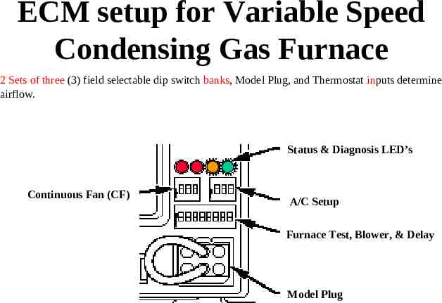
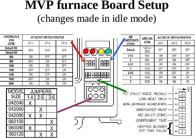
ECM setup for Variable Speed Condensing Gas Furnace 2 Sets of three (3) field selectable dip switch banks, Model Plug, and Thermostat inputs determine airflow. Status & Diagnosis LED’s Continuous Fan (CF) A/C Setup Furnace Test, Blower, & Delay Model Plug
MVP furnace Board Setup (changes made in idle mode)
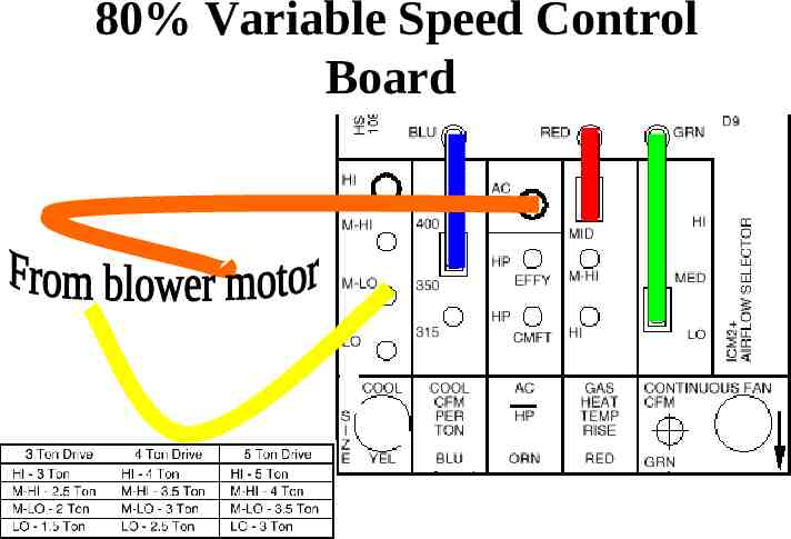
80% Variable Speed Control Board
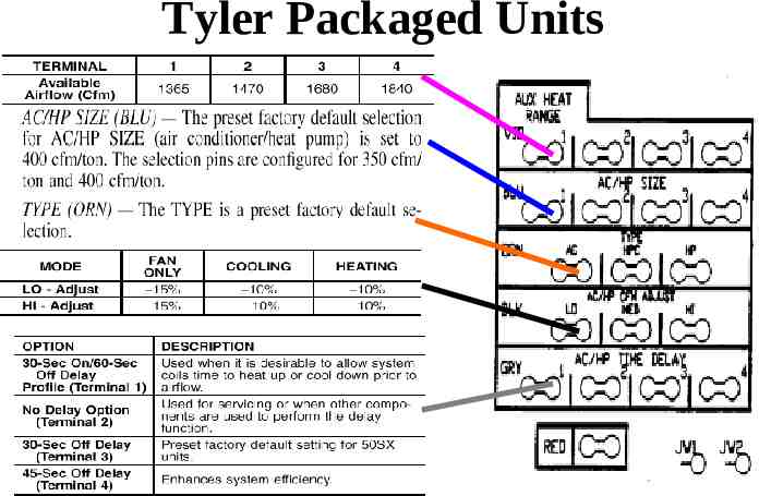
Tyler Packaged Units
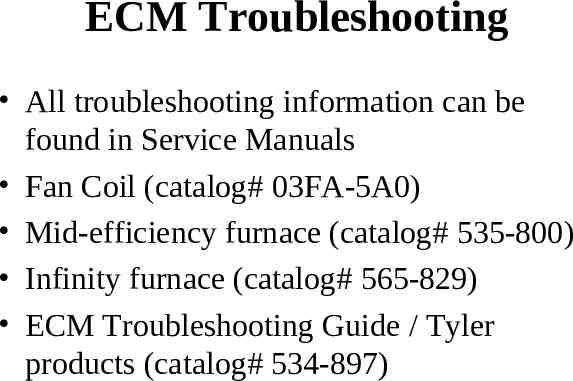
ECM Troubleshooting
ECM Troubleshooting All troubleshooting information can be found in Service Manuals Fan Coil (catalog# 03FA-5A0) Mid-efficiency furnace (catalog# 535-800) Infinity furnace (catalog# 565-829) ECM Troubleshooting Guide / Tyler products (catalog# 534-897)
All ECM Motors Slight “cogging” or rocking is inherent to all ECM motors – motor is finding its location between stator and rotor and is determining rotation “Rumbling” sound during startup and shutdown – System mechanical resonance (approx 300-400rpm), three (3) permanent magnets (stators) cause the rotor to have a “rumble” during low RPM’s “Fixes” – Don’t replace motor! – Isolate sound: Canvas duct connectors, rubber grommets, etc.
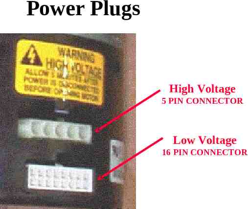
Power Plugs High Voltage 5 PIN CONNECTOR Low Voltage 16 PIN CONNECTOR
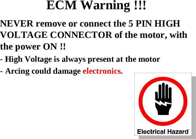
ECM Warning !!! NEVER remove or connect the 5 PIN HIGH VOLTAGE CONNECTOR of the motor, with the power ON !! - High Voltage is always present at the motor - Arcing could damage electronics.
ECM warning!!! ECM motors should NOT be tested UNLESS under LOAD – Erratic motor behavior could occur without a load (static pressure)
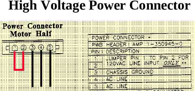
High Voltage Power Connector
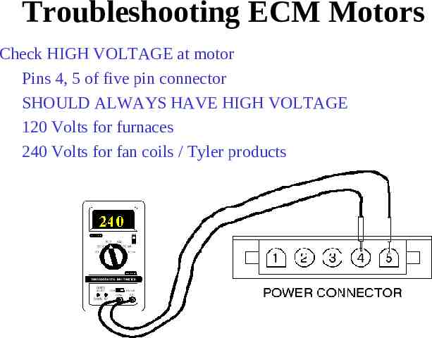
Troubleshooting ECM Motors Check HIGH VOLTAGE at motor Pins 4, 5 of five pin connector SHOULD ALWAYS HAVE HIGH VOLTAGE 120 Volts for furnaces 240 Volts for fan coils / Tyler products
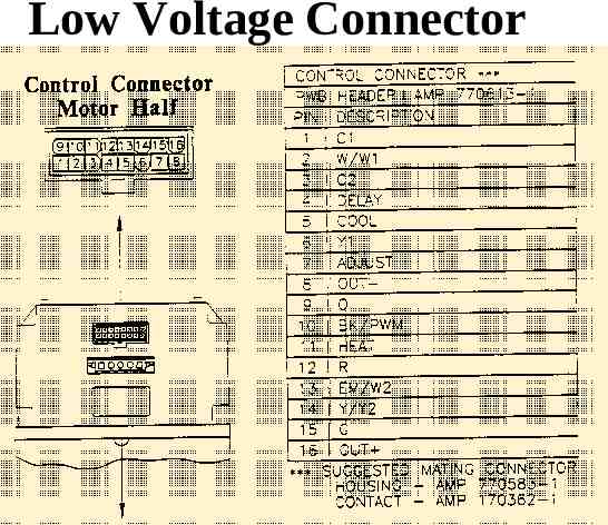
Low Voltage Connector
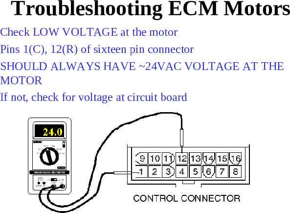
Troubleshooting ECM Motors Check LOW VOLTAGE at the motor Pins 1(C), 12(R) of sixteen pin connector SHOULD ALWAYS HAVE 24VAC VOLTAGE AT THE MOTOR If not, check for voltage at circuit board
ECM Motor shaft turns, but not smoothly If the shaft (with blower wheel disconnected) is difficult to turn with the motor control attached: - and turns freely with the control disconnected, then the control is damaged. - and does not turn free with the control disconnected, then the motor is damaged. Verify continuity of windings (motor leads to unpainted motor end plate). They should be 100K
ECM Motor won’t stop running Check for good ground between – – – – motor ground transformer common lead Thermostat wiring Control Board Remove 12 pin connector, if motor stops it’s control wiring. If it continues to run, motor is bad.
Replacement Issues Insert Blower motor as far into cradle as possible – air over motor helps keep motor cool Verify proper installation of motor to prevent water entering pin connections – Drip legs, proper positioning Beware of electronic thermostats (90% furnaces) – units that notch the waveforms – “Power-Stealing”
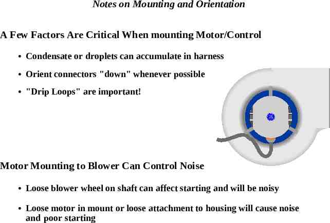
Notes on Mounting and Orientation A Few Factors Are Critical When mounting Motor/Control Condensate or droplets can accumulate in harness Orient connectors "down" whenever possible "Drip Loops" are important! Motor Mounting to Blower Can Control Noise Loose blower wheel on shaft can affect starting and will be noisy Loose motor in mount or loose attachment to housing will cause noise and poor starting
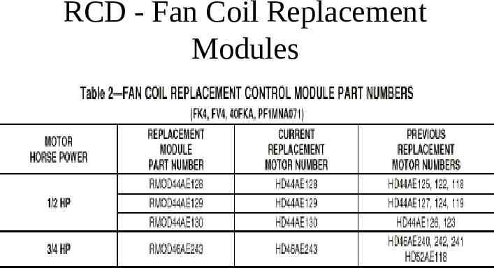
RCD - Fan Coil Replacement Modules
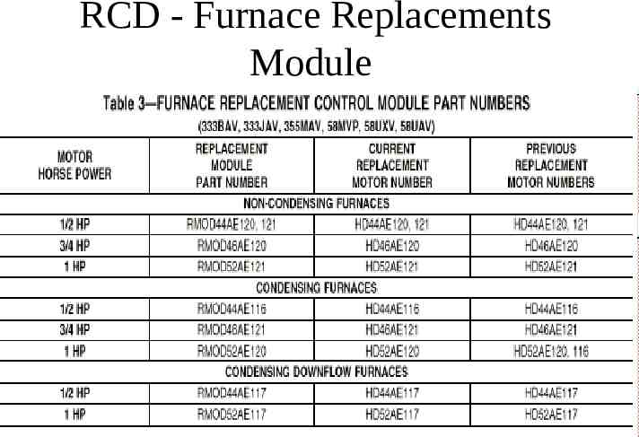
RCD - Furnace Replacements Module
Pulse Width Modulation (PWM) Troubleshooting
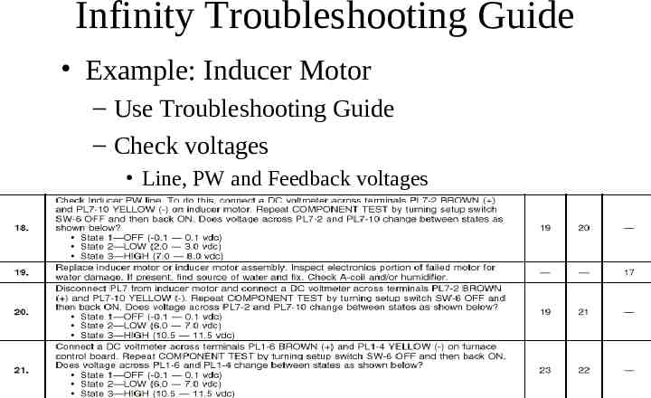
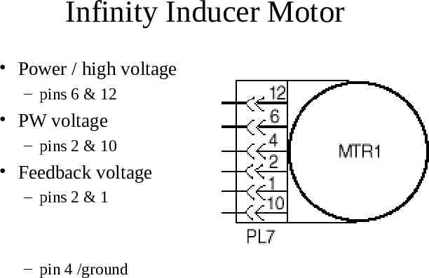
Infinity Troubleshooting Guide Example: Inducer Motor – Use Troubleshooting Guide – Check voltages Line, PW and Feedback voltages
Infinity Inducer Motor Power / high voltage – pins 6 & 12 PW voltage – pins 2 & 10 Feedback voltage – pins 2 & 1 – pin 4 /ground
Advanced Product Monitor (APM) APM kit will help troubleshoot the furnace, including the ECM motors Requires: – Laptop – Software – B&B RS485 Adapter
ECM Motor Simulator (for HK42FZ003 /012 Only) 1. Shut off power to the unit 2. Disconnect PL13 and plug it into the ECM Motor Simulator 3. Turn power on to unit 4. Put setup switch SW-6 to the “ON” position 5. Observe fault code displayed
Thermostatic ECM Troubleshooting
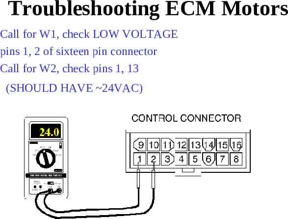
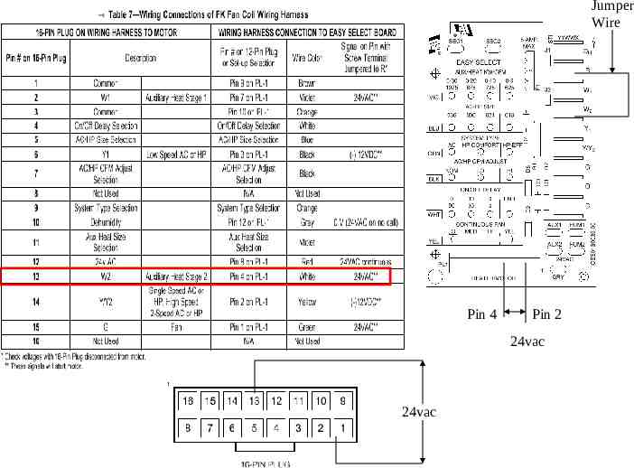
Troubleshooting ECM Motors Call for W1, check LOW VOLTAGE pins 1, 2 of sixteen pin connector Call for W2, check pins 1, 13 (SHOULD HAVE 24VAC)
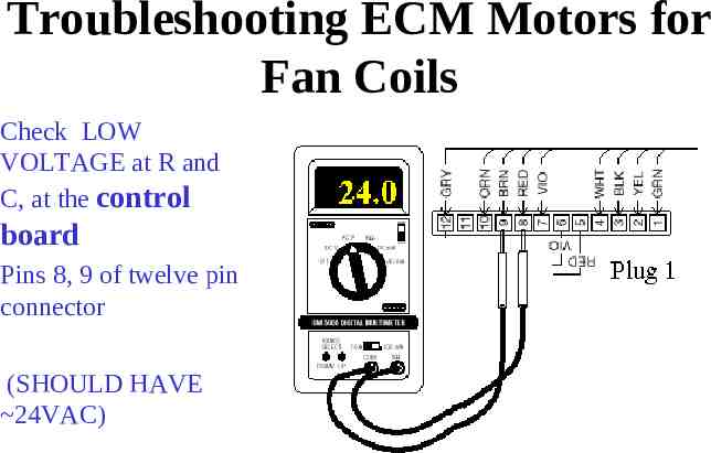
Troubleshooting ECM Motors for Fan Coils Check LOW VOLTAGE at R and C, at the control board Pins 8, 9 of twelve pin connector (SHOULD HAVE 24VAC)
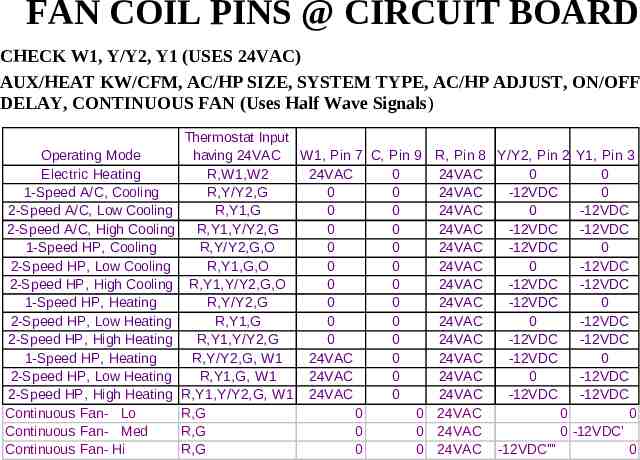
FAN COIL PINS @ CIRCUIT BOARD CHECK W1, Y/Y2, Y1 (USES 24VAC) AUX/HEAT KW/CFM, AC/HP SIZE, SYSTEM TYPE, AC/HP ADJUST, ON/OFF DELAY, CONTINUOUS FAN (Uses Half Wave Signals) Operating Mode Electric Heating 1-Speed A/C, Cooling 2-Speed A/C, Low Cooling 2-Speed A/C, High Cooling 1-Speed HP, Cooling 2-Speed HP, Low Cooling 2-Speed HP, High Cooling 1-Speed HP, Heating 2-Speed HP, Low Heating 2-Speed HP, High Heating 1-Speed HP, Heating 2-Speed HP, Low Heating 2-Speed HP, High Heating Continuous Fan- Lo Continuous Fan- Med Continuous Fan- Hi Thermostat Input having 24VAC W1, Pin 7 C, Pin 9 R,W1,W2 24VAC 0 R,Y/Y2,G 0 0 R,Y1,G 0 0 R,Y1,Y/Y2,G 0 0 R,Y/Y2,G,O 0 0 R,Y1,G,O 0 0 R,Y1,Y/Y2,G,O 0 0 R,Y/Y2,G 0 0 R,Y1,G 0 0 R,Y1,Y/Y2,G 0 0 R,Y/Y2,G, W1 24VAC 0 R,Y1,G, W1 24VAC 0 R,Y1,Y/Y2,G, W1 24VAC 0 R,G 0 0 R,G 0 0 R,G 0 0 R, Pin 8 Y/Y2, Pin 2 Y1, Pin 3 24VAC 0 0 24VAC -12VDC 0 24VAC 0 -12VDC 24VAC -12VDC -12VDC 24VAC -12VDC 0 24VAC 0 -12VDC 24VAC -12VDC -12VDC 24VAC -12VDC 0 24VAC 0 -12VDC 24VAC -12VDC -12VDC 24VAC -12VDC 0 24VAC 0 -12VDC 24VAC -12VDC -12VDC 24VAC 0 0 24VAC 0 -12VDC' 24VAC -12VDC'''' 0
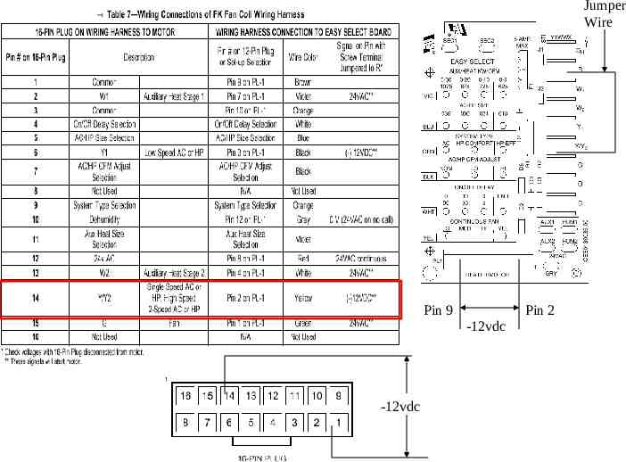
Newest FK4C installation instructions New instructions have more troubleshooting tables and examples Form # IM-FK4C-07 Catalog# 63FK-4C3
Jumper Wire Pin 9 Pin 2 -12vdc -12vdc
Jumper Wire Pin 4 Pin 2 24vac 24vac
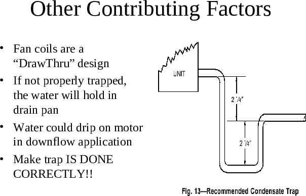
Other Contributing Factors Fan coils are a “DrawThru” design If not properly trapped, the water will hold in drain pan Water could drip on motor in downflow application Make trap IS DONE CORRECTLY!!
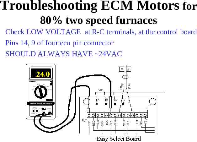
Troubleshooting ECM Motors for 80% two speed furnaces Check LOW VOLTAGE at R-C terminals, at the control board Pins 14, 9 of fourteen pin connector SHOULD ALWAYS HAVE 24VAC
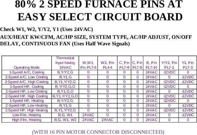
80% 2 SPEED FURNACE PINS AT EASY SELECT CIRCUIT BOARD Check W1, W2, Y/Y2, Y1 (Uses 24VAC) AUX/HEAT KW/CFM, AC/HP SIZE, SYSTEM TYPE, AC/HP ADJUST, ON/OFF DELAY, CONTINUOUS FAN (Uses Half Wave Signals) Operating Mode 1-Speed A/C, Cooling 2-Speed A/C, Low Cooling 2-Speed A/C, High Cooling 1-Speed HP, Cooling 2-Speed HP, Low Cooling 2-Speed HP, High Cooling 1-Speed HP, Heating 2-Speed HP, Low Heating 2-Speed HP, High Heating Low Fire, Heating High Fire, Heating Thermostat Input having W,W1, 24VAC Pin PL7-6 R,Y/Y2,G 0 R,Y1,G 0 R,Y1,Y/Y2,G 0 R,Y/Y2,G,O 0 R,Y1,G,O 0 R,Y1,Y/Y2,G,O 0 R,Y/Y2,G 0 R,Y1,G 0 R,Y1,Y/Y2,G 0 R,G, W1 24VAC R,G, W1, W2 24VAC W2, Pin PL4-4 0 0 0 0 0 0 0 0 0 0 24VAC C, Pin C, Pin PL7-9 PL7-8 0 0 0 0 0 0 0 0 0 0 0 0 0 0 0 0 0 0 0 0 0 0 R, Pin PL7-14 24VAC 24VAC 24VAC 24VAC 24VAC 24VAC 24VAC 24VAC 24VAC 24VAC 24VAC Y/Y2, Pin PL7-1 -12VDC 0 -12VDC -12VDC 0 -12VDC -12VDC 0 -12VDC 0 0 (WITH 16 PIN MOTOR CONNECTOR DISCONNECTED) Y1, Pin PL7-3 0 -12VDC -12VDC 0 -12VDC -12VDC 0 -12VDC -12VDC -12VDC 0
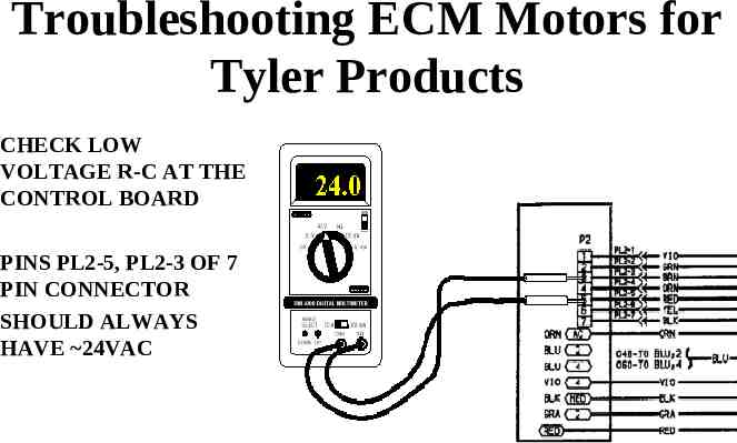
Troubleshooting ECM Motors for Tyler Products CHECK LOW VOLTAGE R-C AT THE CONTROL BOARD PINS PL2-5, PL2-3 OF 7 PIN CONNECTOR SHOULD ALWAYS HAVE 24VAC
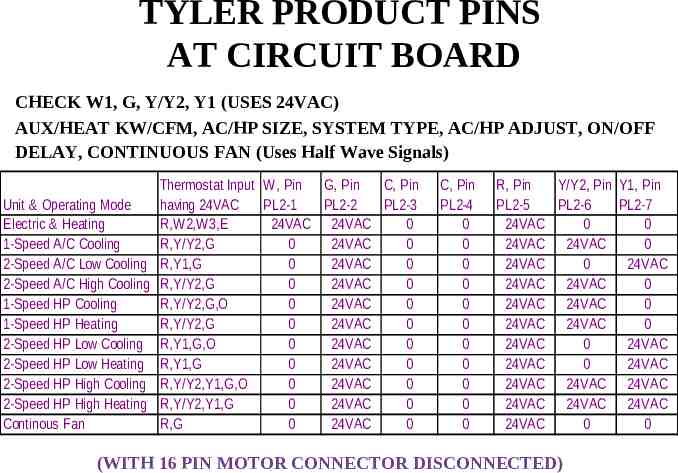
TYLER PRODUCT PINS AT CIRCUIT BOARD CHECK W1, G, Y/Y2, Y1 (USES 24VAC) AUX/HEAT KW/CFM, AC/HP SIZE, SYSTEM TYPE, AC/HP ADJUST, ON/OFF DELAY, CONTINUOUS FAN (Uses Half Wave Signals) Unit & Operating Mode Electric & Heating 1-Speed A/C Cooling 2-Speed A/C Low Cooling 2-Speed A/C High Cooling 1-Speed HP Cooling 1-Speed HP Heating 2-Speed HP Low Cooling 2-Speed HP Low Heating 2-Speed HP High Cooling 2-Speed HP High Heating Continous Fan Thermostat Input W, Pin G, Pin C, Pin having 24VAC PL2-1 PL2-2 PL2-3 R,W2,W3,E 24VAC 24VAC 0 R,Y/Y2,G 0 24VAC 0 R,Y1,G 0 24VAC 0 R,Y/Y2,G 0 24VAC 0 R,Y/Y2,G,O 0 24VAC 0 R,Y/Y2,G 0 24VAC 0 R,Y1,G,O 0 24VAC 0 R,Y1,G 0 24VAC 0 R,Y/Y2,Y1,G,O 0 24VAC 0 R,Y/Y2,Y1,G 0 24VAC 0 R,G 0 24VAC 0 C, Pin PL2-4 0 0 0 0 0 0 0 0 0 0 0 R, Pin Y/Y2, Pin Y1, Pin PL2-5 PL2-6 PL2-7 24VAC 0 0 24VAC 24VAC 0 24VAC 0 24VAC 24VAC 24VAC 0 24VAC 24VAC 0 24VAC 24VAC 0 24VAC 0 24VAC 24VAC 0 24VAC 24VAC 24VAC 24VAC 24VAC 24VAC 24VAC 24VAC 0 0 (WITH 16 PIN MOTOR CONNECTOR DISCONNECTED)
Proper Ductwork Installation Check existing ductwork static pressure Determine existing equipment CFM Use Product Data Sheet to determine that new equipment will work with existing ductwork or if it will require ductwork modifications – See following examples
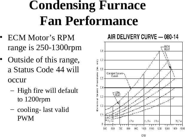
Condensing Furnace Fan Performance ECM Motor’s RPM range is 250-1300rpm Outside of this range, a Status Code 44 will occur – High fire will default to 1200rpm – cooling- last valid PWM
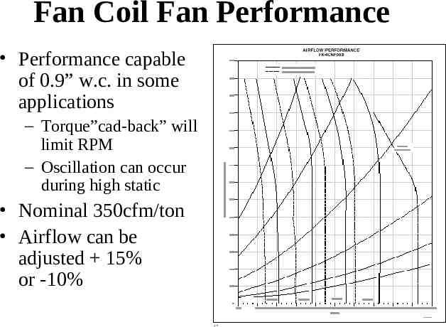
Fan Coil Fan Performance Performance capable of 0.9” w.c. in some applications – Torque”cad-back” will limit RPM – Oscillation can occur during high static Nominal 350cfm/ton Airflow can be adjusted 15% or -10%
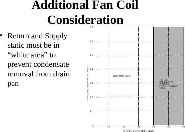
Additional Fan Coil Consideration Return and Supply static must be in “white area” to prevent condensate removal from drain pan
Other things to consider An ECM motor will out-perform a PSC motor in high static situations – Condensing furnace will display a fault code (above 1300rpm’s) but still provide more CFM than standard PSC motor at comparable external static pressure – Thermostatically Controlled motors will provide desired CFM in high static situations