Ethernet Outline Multiple Access and Ethernet Intro Ethernet Framing


25 Slides166.50 KB
Ethernet Outline Multiple Access and Ethernet Intro Ethernet Framing CSMA/CD protocol Exponential backoff
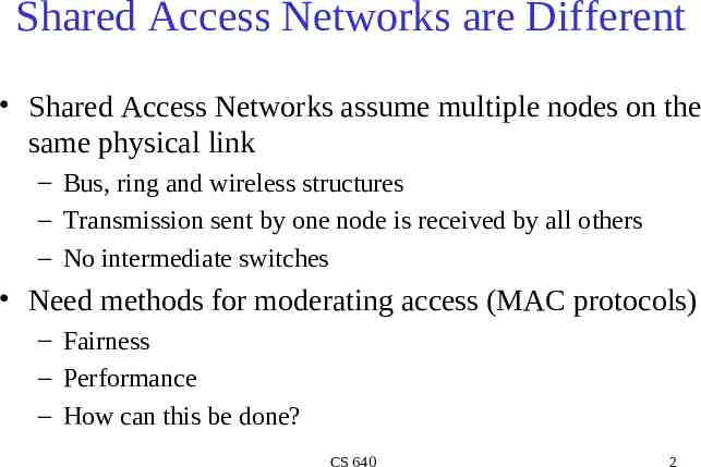
Shared Access Networks are Different Shared Access Networks assume multiple nodes on the same physical link – Bus, ring and wireless structures – Transmission sent by one node is received by all others – No intermediate switches Need methods for moderating access (MAC protocols) – Fairness – Performance – How can this be done? CS 640 2
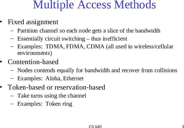
Multiple Access Methods Fixed assignment – Partition channel so each node gets a slice of the bandwidth – Essentially circuit switching – thus inefficient – Examples: TDMA, FDMA, CDMA (all used in wireless/cellular environments) Contention-based – Nodes contends equally for bandwidth and recover from collisions – Examples: Aloha, Ethernet Token-based or reservation-based – Take turns using the channel – Examples: Token ring CS 640 3
A Quick Word about Token Ring Developed by IBM in early 80’s as a new LAN architecture – Consists of nodes connected into a ring (typically via concentrators) – Special message called a token is passed around the ring When nodes gets the token it can transmit for a limited time Every node gets an equal opportunity to send – IEEE 802.5 standard for Token Ring Designed for predictability, fairness and reliability – Originally designed to run at either 4Mbps and 16Mbps Still used and sold but beaten out by Ethernet CS 640 4
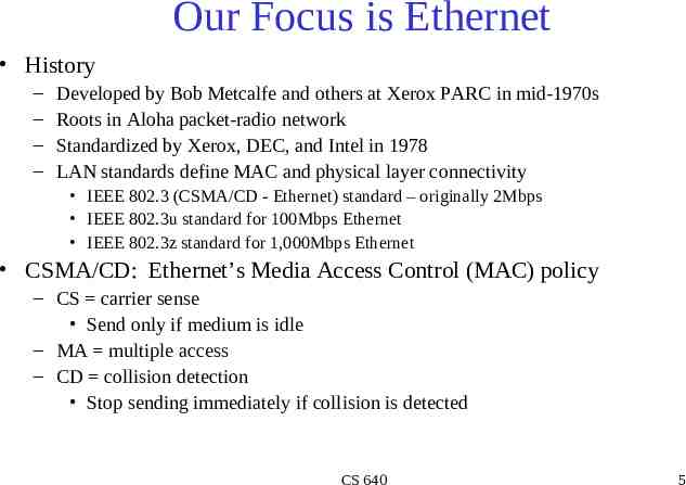
Our Focus is Ethernet History – – – – Developed by Bob Metcalfe and others at Xerox PARC in mid-1970s Roots in Aloha packet-radio network Standardized by Xerox, DEC, and Intel in 1978 LAN standards define MAC and physical layer connectivity IEEE 802.3 (CSMA/CD - Ethernet) standard – originally 2Mbps IEEE 802.3u standard for 100Mbps Ethernet IEEE 802.3z standard for 1,000Mbps Ethernet CSMA/CD: Ethernet’s Media Access Control (MAC) policy – CS carrier sense Send only if medium is idle – MA multiple access – CD collision detection Stop sending immediately if collision is detected CS 640 5
Ethernet Standard Defines Physical Layer 802.3 standard defines both MAC and physical layer details Metcalfe’s original Ethernet Sketch CS 640 6
Ethernet Technologies: 10Base2 10: 10Mbps; 2: under 185 ( 200) meters cable length Thin coaxial cable in a bus topology Repeaters used to connect multiple segments – Repeater repeats bits it hears on one interface to its other interfaces: physical layer device only! CS 640 7
10BaseT and 100BaseT 10/100 Mbps rate T stands for Twisted Pair Hub(s) connected by twisted pair facilitate “star topology” – Distance of any node to hub must be 100M CS 640 8
Physical Layer Configurations for 802.3 Physical layer configurations are specified in three parts Data rate (10, 100, 1,000) – 10, 100, 1,000Mbps Signaling method (base, broad) – Baseband Digital signaling – Broadband Analog signaling Cabling (2, 5, T, F, S, L) – – – – 5 - Thick coax (original Ethernet cabling) F – Optical fiber S – Short wave laser over multimode fiber L – Long wave laser over single mode fiber CS 640 9
Ethernet Overview Most popular packet-switched LAN technology Bandwidths: 10Mbps, 100Mbps, 1Gbps Max bus length: 2500m – 500m segments with 4 repeaters Bus and Star topologies are used to connect hosts – Hosts attach to network via Ethernet transceiver or hub or switch Detects line state and sends/receives signals – Hubs are used to facilitate shared connections – All hosts on an Ethernet are competing for access to the medium Switches break this model Problem: Distributed algorithm that provides fair access CS 640 10
Ethernet Overview (contd.) Ethernet by definition is a broadcast protocol – Any signal can be received by all hosts – Switching enables individual hosts to communicate Network layer packets are transmitted over an Ethernet by encapsulating Frame Format 64 48 48 16 Preamble Dest addr Src addr Type CS 640 32 Body CRC 11
Switched Ethernet Switches forward and filter frames based on LAN addresses – It’s not a bus or a router (although simple forwarding tables are maintained) Very scalable – Options for many interfaces – Full duplex operation (send/receive frames simultaneously) Connect two or more “segments” by copying data frames between them – Switches only copy data when needed key difference from repeaters Higher link bandwidth – Collisions are completely avoided Much greater aggregate bandwidth – Separate segments can send at once CS 640 12
Ethernet Frames Preamble is a sequence of 7 bytes, each set to “10101010” – Used to synchronize receiver before actual data is sent Addresses – unique, 48-bit unicast address assigned to each adapter example: 8:0:e4:b1:2 Each manufacturer gets their own address range – broadcast: all 1s – multicast: first bit is 1 Type field is a demultiplexing key used to determine which higher level protocol the frame should be delivered to Body can contain up to 1500 bytes of data CS 640 13
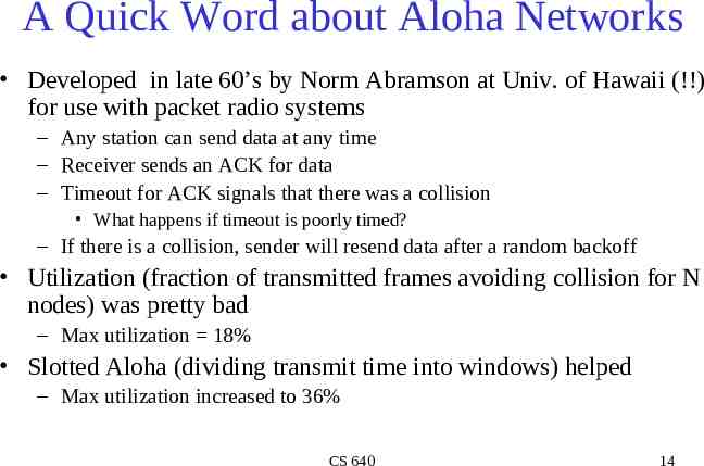
A Quick Word about Aloha Networks Developed in late 60’s by Norm Abramson at Univ. of Hawaii (!!) for use with packet radio systems – Any station can send data at any time – Receiver sends an ACK for data – Timeout for ACK signals that there was a collision What happens if timeout is poorly timed? – If there is a collision, sender will resend data after a random backoff Utilization (fraction of transmitted frames avoiding collision for N nodes) was pretty bad – Max utilization 18% Slotted Aloha (dividing transmit time into windows) helped – Max utilization increased to 36% CS 640 14
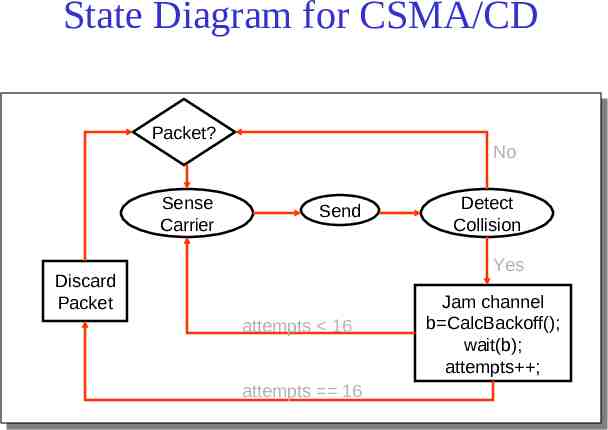
Ethernet’s MAC Algorithm In Aloha, decisions to transmit are made without paying attention to what other nodes might be doing Ethernet uses CSMA/CD – listens to line before/during sending If line is idle (no carrier sensed) – send packet immediately – upper bound message size of 1500 bytes – must wait 9.6us between back-to-back frames If line is busy (carrier sensed) – wait until idle and transmit packet immediately called 1-persistent sending If collision detected – Stop sending and jam signal – Try again later CS 640 15
State Diagram for CSMA/CD Packet? Sense Carrier No Send Detect Collision Yes Discard Packet attempts 16 Jam channel b CalcBackoff(); wait(b); attempts ; attempts 16 CS 640 16
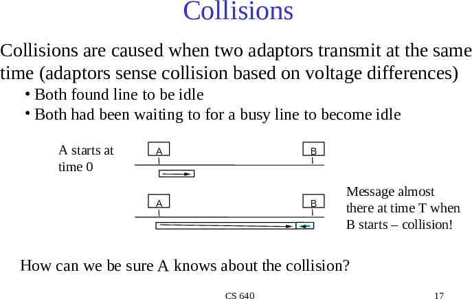
Collisions Collisions are caused when two adaptors transmit at the same time (adaptors sense collision based on voltage differences) Both found line to be idle Both had been waiting to for a busy line to become idle A starts at time 0 A B A B Message almost there at time T when B starts – collision! How can we be sure A knows about the collision? CS 640 17
Collision Detection How can A know that a collision has taken place? – – – – There must be a mechanism to insure retransmission on collision A’s message reaches B at time T B’s message reaches A at time 2T So, A must still be transmitting at 2T IEEE 802.3 specifies max value of 2T to be 51.2us – This relates to maximum distance of 2500m between hosts – At 10Mbps it takes 0.1us to transmit one bit so 512 bits (64B) take 51.2us to send – So, Ethernet frames must be at least 64B long 14B header, 46B data, 4B CRC Padding is used if data is less than 46B Send jamming signal after collision is detected to insure all hosts see collision – 48 bit signal CS 640 18
Collision Detection contd. time 0 A B A B A B time T time 2T CS 640 19
Exponential Backoff If a collision is detected, delay and try again Delay time is selected using binary exponential backoff – 1st time: choose K from {0,1} then delay K * 51.2us – 2nd time: choose K from {0,1,2,3} then delay K * 51.2us – nth time: delay K x 51.2us, for K 0.2n – 1 Note max value for k 1023 – give up after several tries (usually 16) Report transmit error to host If delay were not random, then there is a chance that sources would retransmit in lock step Why not just choose from small set for K – This works fine for a small number of hosts – Large number of nodes would result in more collisions CS 640 20
MAC Algorithm from the Receiver Side Senders handle all access control Receivers simply read frames with acceptable address – – – – Address to host Address to broadcast Address to multicast to which host belongs All frames if host is in promiscuous mode CS 640 21
Fast and Gigabit Ethernet Fast Ethernet (100Mbps) has technology very similar to 10Mbps Ethernet – Uses different physical layer encoding (4B5B) – Many NIC’s are 10/100 capable Can be used at either speed Gigabit Ethernet (1,000Mbps) – – – – – – Compatible with lower speeds Uses standard framing and CSMA/CD algorithm Distances are severely limited Typically used for backbones and inter-router connectivity Becoming cost competitive How much of this bandwidth is realizable? CS 640 22
Experiences with Ethernet Ethernets work best under light loads – Utilization over 30% is considered heavy Network capacity is wasted by collisions Most networks are limited to about 200 hosts – Specification allows for up to 1024 Most networks are much shorter – 5 to 10 microsecond RTT Transport level flow control helps reduce load (number of back to back packets) Ethernet is inexpensive, fast and easy to administer! CS 640 23
Ethernet Problems Ethernet’s peak utilization is pretty low (like Aloha) Peak throughput worst with – More hosts More collisions needed to identify single sender – Smaller packet sizes More frequent arbitration – Longer links Collisions take longer to observe, more wasted bandwidth – Efficiency is improved by avoiding these conditions CS 640 24
Why did Ethernet Win? There are LOTS of LAN protocols Price Performance Availability Ease of use Scalability Tomorrow we will talk about physical layer stuff CS 640 25