Engineering Geology Course Material for Civil Engineers Module –
38 Slides9.24 MB
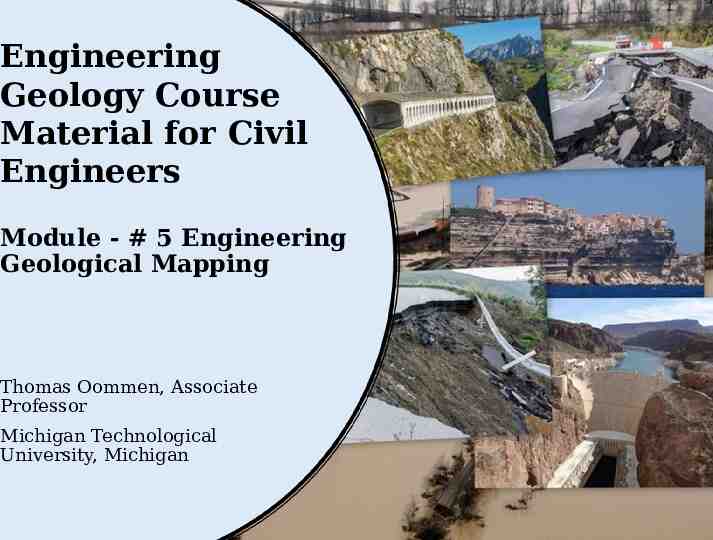
Engineering Geology Course Material for Civil Engineers Module - # 5 Engineering Geological Mapping Thomas Oommen, Associate Professor Michigan Technological University, Michigan
Content Introduction Principles of Engineering Geological Mapping (EGM) How to make engineering geological maps Rock and soil description and classification for EGM Terrain evaluation: cost-effective mapping Reference Textbook: Dearman, W. R. Engineering geological mapping. ButterworthHeinemann, 1991.
Introduction Engineer Geologic Mapping (EGM) is a guide to the principles, concepts, methods, and practices involved in geological mapping, as well as the applications of geology in engineering.
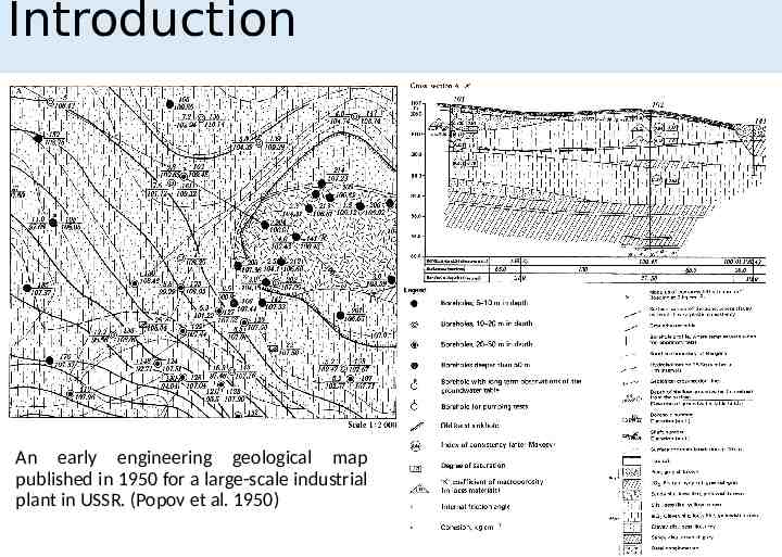
Introduction An early engineering geological map published in 1950 for a large-scale industrial plant in USSR. (Popov et al. 1950)
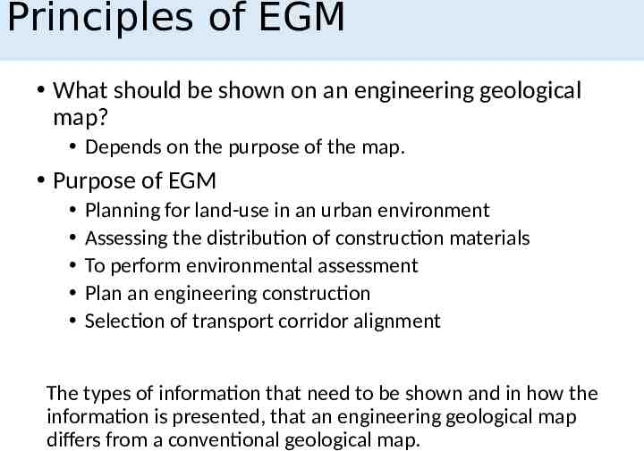
Principles of EGM What should be shown on an engineering geological map? Depends on the purpose of the map. Purpose of EGM Planning for land-use in an urban environment Assessing the distribution of construction materials To perform environmental assessment Plan an engineering construction Selection of transport corridor alignment The types of information that need to be shown and in how the information is presented, that an engineering geological map differs from a conventional geological map.
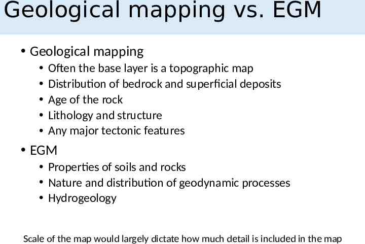
Geological mapping vs. EGM Geological mapping Often the base layer is a topographic map Distribution of bedrock and superficial deposits Age of the rock Lithology and structure Any major tectonic features EGM Properties of soils and rocks Nature and distribution of geodynamic processes Hydrogeology Scale of the map would largely dictate how much detail is included in the map
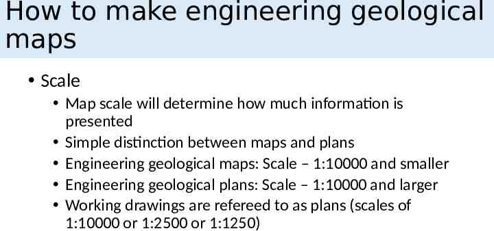
How to make engineering geological maps Scale Map scale will determine how much information is presented Simple distinction between maps and plans Engineering geological maps: Scale – 1:10000 and smaller Engineering geological plans: Scale – 1:10000 and larger Working drawings are refereed to as plans (scales of 1:10000 or 1:2500 or 1:1250)
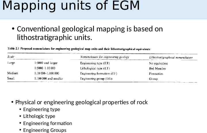
Mapping units of EGM Conventional geological mapping is based on lithostratigraphic units. Physical or engineering geological properties of rock Engineering type Lithologic type Engineering formation Engineering Groups
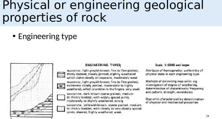
Physical or engineering geological properties of rock Engineering type
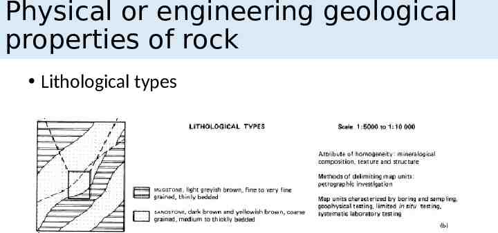
Physical or engineering geological properties of rock Lithological types
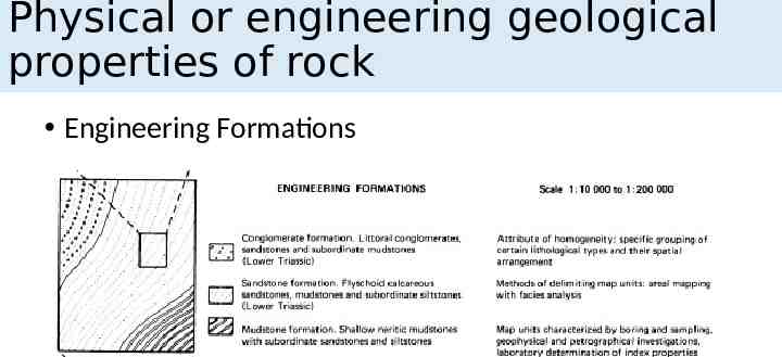
Physical or engineering geological properties of rock Engineering Formations
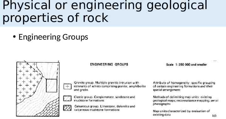
Physical or engineering geological properties of rock Engineering Groups
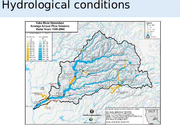
Hydrological conditions Provision of hydrological information on maps facilitates prediction of undesirable changes in the hydrological regime and recommendation of methods to avoid them Distribution of surface and subsurface water Infiltration conditions Water content Direction and velocity of groundwater flow Springs and seepages from water-bearing horizons Depth to water-table and its fluctuation range Hydrochemical properties such as pH, salinity, corrosiveness Presence of bacterial and other pollutants
Hydrological conditions
Geomorphological conditions Evaluation of geomorphological conditions is more than a simple description of surface topography. It should provide explanation for: Relation between surface conditions and geology Origin, age, and development of individual geomorphological elements Influence of geomorphological conditions on hydrology and geodynamic processes Impending development of geomorphological features such as the erosion of river and lake banks, movement of dunes, collapse in karstic or undermined areas
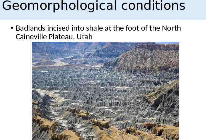
Geomorphological conditions Badlands incised into shale at the foot of the North Caineville Plateau, Utah
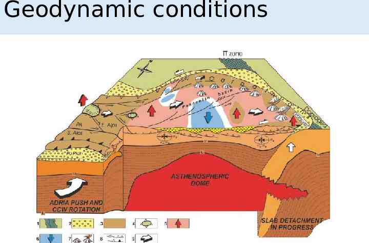
Geodynamic conditions Seismic and volcanic activity and neo-tectonic movements resulting in uplift or depression of the surface. Mappable features include: Intensity of seismic event: using isoseismal lines Surface expression of present-day and historical events Offset streams Terraces and manmade structures Sag ponds Lines of springs Linear trenches and fault scarps
Geodynamic conditions
Methods of conventional geological mapping Geologic field work for conventional field mapping includes: The study and interpretation of rocks and soils, topographic forms and significant geomorphological and other processes The determination of the location of points or outcrops where observations are made Plotting of these outcrops and other geologic data on a map
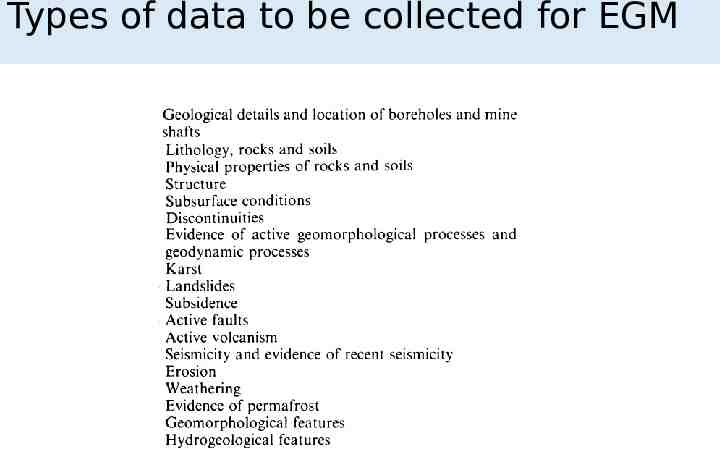
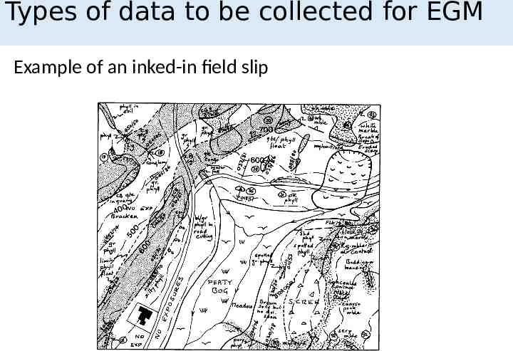
Types of data to be collected for EGM
Types of data to be collected for EGM Example of an inked-in field slip
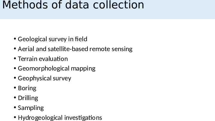
Methods of data collection Geological survey in field Aerial and satellite-based remote sensing Terrain evaluation Geomorphological mapping Geophysical survey Boring Drilling Sampling Hydrogeological investigations
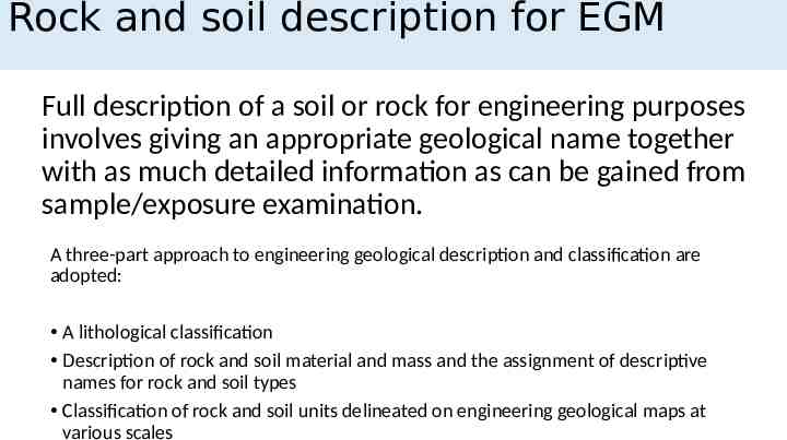
Rock and soil description for EGM Full description of a soil or rock for engineering purposes involves giving an appropriate geological name together with as much detailed information as can be gained from sample/exposure examination. A three-part approach to engineering geological description and classification are adopted: A lithological classification Description of rock and soil material and mass and the assignment of descriptive names for rock and soil types Classification of rock and soil units delineated on engineering geological maps at various scales
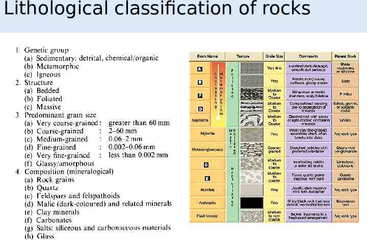
Lithological classification of rocks
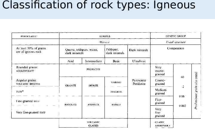
Classification of rock types: Igneous
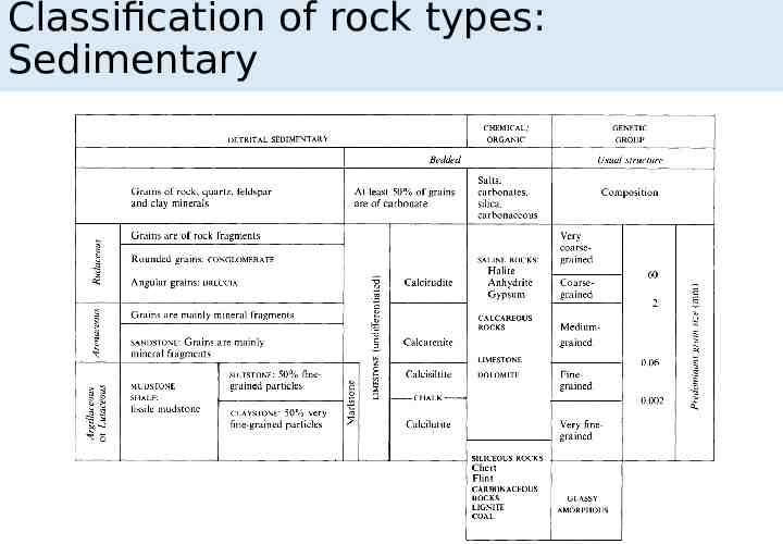
Classification of rock types: Sedimentary
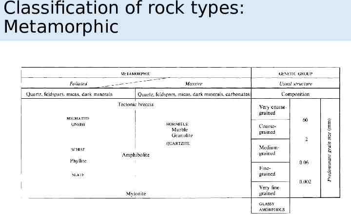
Classification of rock types: Metamorphic
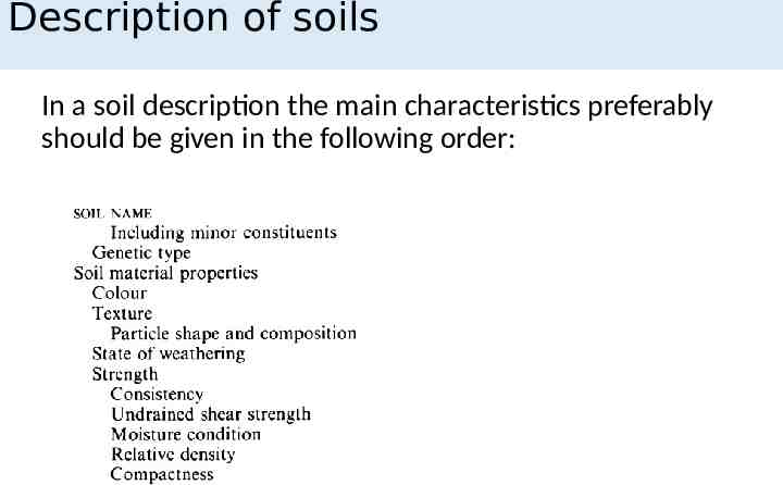
Description of soils In a soil description the main characteristics preferably should be given in the following order:
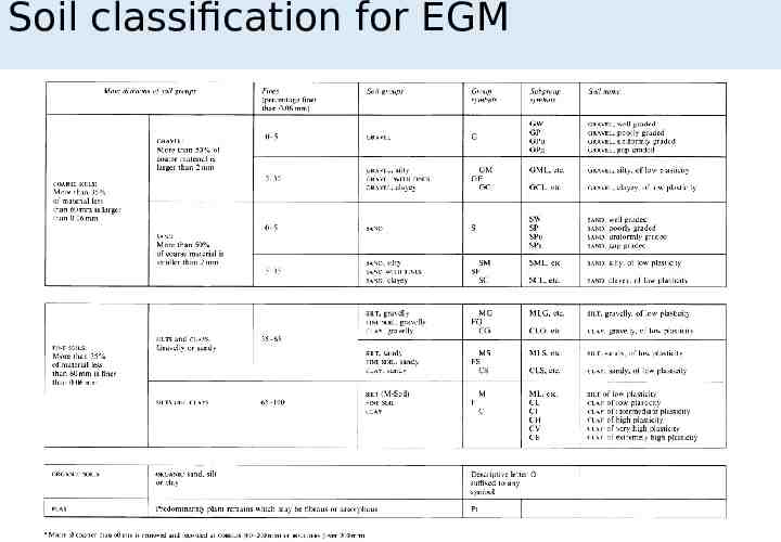
Soil classification for EGM
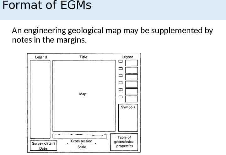
Format of EGMs An engineering geological map may be supplemented by notes in the margins.
Content of EGMs Geologic Aspects Mappable units: Division of rocks and soils into mappable units Geological boundaries: An indication should be given of the accuracy of geologic boundaries between Mappable units Description of rocks and soils: Should follow the standard formats Description of exposures: Exposures of rock should give structural description with symbols Description of weathering and alteration: Notes on the distribution, depth and nature of weathering and alteration must be given wherever possible Description of joints and other structural planes: Jointing of rock, visible faults, bedding and cleavage Subsurface conditions: Where enough information is available, isopachytes and contours of selected horizons may be given
Content of EGMs Hydrogeological Aspects General hydrogeological conditions: Includes notes in the legend of the general hydrogeological condition of the area. This could include notes on groundwater basins, artesian overflow areas, qualitative permeability, boundaries between saline and portable water. Hydrogeological conditions should be quantified wherever possible and all relevant hydrogeological information should be given, including piezometric levels, coefficient of permeability based on in situ or laboratory determinations, storage coefficient and geochemical parameters (groundwater and formation water chemistry). Hydrogeological properties of rocks and soils: Aquifers, aquitards, aquicludes and aquifuges should be distinguished by a simple convention. Springs and seepages: Springs, both permanent and intermittent, should be marked by symbols; seepage lines should be indicated by notes or symbols. Periodic streams, or bournes, should be shown wherever possible.
Content of EGMs Geomorphological Aspects General: Geomorphological features should be shown by notes on the map, for example steep scarp, gentle dip slope, or by the symbols given wherever practicable or where space permits. Mass movements: Landslips, subsidences, solifluxion features, cambering phenomena and any other mass movement features should be shown using the symbols given. Seismicity: Any recorded seismic activity should be noted.
Content of EGMs Boreholes General: Boreholes and wells should be classified according to purpose, and details should be given of the rocks and soils penetrated. Site investigation and tests General: Construction and other sites should be marked for which a site investigation has been made. The locations of any isolated samples or geophysical information should be noted. Mines and quarries General: All mines and quarries, whether active or abandoned, should be noted together with dates of working.
Terrain evaluation: cost-effective mapping EGMs at small scale are generally prepared by a combination of compilation and reduction from existing larger scale maps Aerial photographs play a major role In heavily forested areas aerial photo is of doubtful use and extensive field work may be required Satellite imagery can supplement aerial photographs
Terrain evaluation: cost-effective mapping Schedule: Prioritize work to be done Extent of previous studies: Collect and study all available geologic literature for the study area Photography: Aerial and terrestrial photography should be reviewed Suggested equipment: Brunton compass, geologist hammer, maps, map board, aerial photographs, notebook, scale, tape measure, protractor, knife, hand lens, pens and pencils, GPS
Mapping Exercise Prepare an engineering geology map of a local site What are the main steps of an engineering geology mapping exercise The link below provide the engineering geology map of UK. Download the map and describe the relation between bedrock structural complexity and relative permeability. http:// www.bgs.ac.uk/research/engineeringGeology/ggpp/ maps.html
Cite as: M. Ciancia, N. Huydma, T. Oommen, R. Player, K.S. Sajinkumar, A. Shidlovskaya (2017) Engineering Geology Course Material for Civil Engineers, ASCE Geoinstitute Technical Committee on Engineering Geology and Site Characterization.