ECE 683 Computer Network Design & Analysis Note 4: Circuit-Switching


52 Slides915.50 KB
ECE 683 Computer Network Design & Analysis Note 4: Circuit-Switching Networks 1
Circuit Switching Networks End-to-end dedicated circuits between clients – Client can be a person or equipment (router or switch) Circuit can take different forms – – – – Dedicated path for the transfer of electrical current Dedicated time slots for transfer of voice samples Dedicated frames for transfer of Nx51.84 Mbps signals Dedicated wavelengths for transfer of optical signals Circuit switching networks require: – Multiplexing & switching of circuits – Signaling & control for establishing circuits These are the subjects covered in this chapter 2
Outline Multiplexing – TDM/FDM/WDM/CDM Circuit switches – Space-division switches – Time-division switches Telephone network Signaling Cellular telephone networks 3
Multiplexing Multiplexing: sharing of an expensive transmission channel by multiple connections or information flows – Channel 1 wire, 1 optical fiber, or 1 frequency band Implicit or explicit information is required to demultiplex the information flows (a) (b) A A A B B B C C C A Trunk group MUX MUX B C 4
Frequency-Division Multiplexing (FDM) Channel divided into frequency slots A Wu 0 (a) Individual signals occupy Wu Hz f B 0 f Wu C (b) Combined signal fits into channel bandwidth A 0 f Wu 0 B C W f Guard bands required AM or FM radio stations TV stations in air or cable Analog telephone systems 5
FDM System Overview 6
Time-Division Multiplexing (TDM) High-speed digital channel divided into time slots A1 A2 0T (a) Each signal transmits 1 unit every 3T seconds B2 C1 C2 0T (b) Combined signal transmits 1 unit every T seconds 0T 1T 2T C1 A2 3T 4T t t t 6T 3T A1 B1 6T 3T 0T t 6T 3T B1 B2 C2 Framing required Telephone digital transmission Digital transmission in backbone network 5T 6T 7
T-Carrier System Digital telephone system uses TDM. PCM voice channel is basic unit for TDM – 1 channel 8 bits/sample x 8000 samples/sec. 64 kbps T-1 carrier carries Digital Signal 1 (DS-1) that combines 24 voice channels into a digital stream: 1 24 MUX MUX 22 23 24 b 1 2 . 24 b Frame 2 . . 2 1 24 Framing bit Bit Rate 8000 frames/sec. x (1 8 x 24) bits/frame 1.544 Mbps 8
North American Digital Multiplexing Hierarchy 1 24 . . DS1 signal, 1.544Mbps Mux 24 DS0 1 4 DS1 4 . . DS2 signal, 6.312Mbps Mux 1 7 DS2 7 . . DS3 signal, 44.736Mpbs Mux 1 DS0, DS1, DS2, DS3, DS4, 64 Kbps channel 1.544 Mbps channel 6.312 Mbps channel 44.736 Mbps channel 274.176 Mbps channel 6 DS3 6 . . Mux DS4 signal 274.176Mbps 9
CCITT Digital Hierarchy CCITT digital hierarchy based on 30 PCM channels 1 30 . . 64 Kbps 2.048 Mbps Mux 1 4 . . 8.448 Mbps Mux 1 4 E1, E2, E3, E4, 2.048 Mbps channel 8.448 Mbps channel 34.368 Mbps channel 139.264 Mbps channel . 34.368 Mpbs Mux 139.264 Mbps 1 4 . . Mux 10
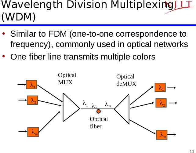
Wavelength Division Multiplexing (WDM) Similar to FDM (one-to-one correspondence to frequency), commonly used in optical networks One fiber line transmits multiple colors 1 2 Optical MUX Optical deMUX 1 2. m 1 2 Optical fiber m m 11
Typical U.S. Optical Long-Haul Network In 1998 12
Code Division Multiplexing (CDM) Different connections or flows use different codes: orthogonal codes are used Commonly used in wireless systems: multiple users share the same channel 13
Note 4: Circuit-Switching Networks Circuit Switches 14
Switching Long distance transmission is typically done over a network of switching nodes Intermediate switching nodes not concerned with content of data End devices are stations – Computer, terminal, phone, etc. Data routed by being switched from node to node (router is a more complicated switch) 15
Simple Switched Network 16
Circuit Switches Blocking – Only finite paths in switches – A switch is unable to connect stations because all paths are in use – Blocking is possible: “all circuits are busy” – Used on voice systems Short duration calls Non-blocking – Permits all stations to connect (in pairs) at once, no blocking inside a switch – Used for some data connections (high speed) 17
Space Division Switching Developed for analog environment Separate physical paths Crossbar switch – Number of crosspoints grows as square of number of stations – Loss of crosspoint prevents connection – Inefficient use of crosspoints All stations connected, only a few crosspoints in use – Non-blocking 18
Crossbar Matrix 19
Multistage Switch Reduced number of crosspoints Increase the scalability More than one path through network – Increased reliability More complex control May be blocking 20
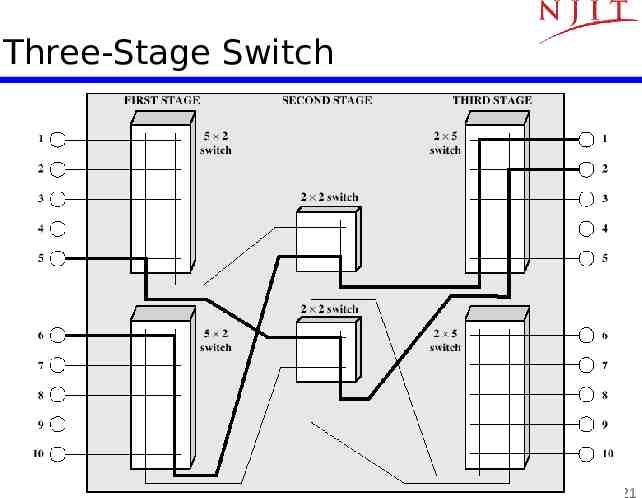
Three-Stage Switch 21
Three-Stage Switch 2(N/n)nk k (N/n)2 crosspoints 1 N/n N/n 1 2 n k N/n N/n 2 2 k n N outputs 3 3 k n n k N/n 1 k n n k N inputs k n n k N/n N/n N/n k 22
[Clos] Non-Blocking Condition: k 2n-1 Request connection from last input to input switch j to last output in output switch m Worst Case: All other inputs have seized top n-1 middle switches AND all other outputs have seized next n-1 middle switches If k 2n-1, there is another path left to connect desired input to desired output nxk j Desired input kxn N/n x N/n n-1 kxn 1 1 n-1 busy 1 N/n x N/n N/n x N/n n 1 m n-1 busy Desired output nxk N/n x N/n 2n-2 nxk N/n x N/n Free path N/n2n-1 Free path kxn N/n 23
Minimum Complexity Clos Switch C(n) number of crosspoints in Clos switch 2Nk k( N)2 2N(2n – 1) (2n – 1)( N )2 n n Differentiate with respect to n: 0 C 4N – 2N2 2N2 4N – n n2 n3 2N2 n n2 The minimized number of crosspoints is then: C* (2N N2 )(2( N )1/2 – 1) 2 N/2 This is lower than N2 for large N 24
Time-Slot Interchange (TSI) Switching Write bytes from arriving TDM stream into memory Read bytes in permuted order into outgoing TDM stream Max # slots 125 sec / (2 x memory cycle time) d 24 c 23 Incoming TDM stream 1 a 2 b 3 b 2 a 1 Write 22 slots in order of 23 arrival 24 Read slots according to connection permutation c d Time-slot interchange b 24 a 23 d 2 c 1 Outgoing TDM stream 25
Time-Space-Time Hybrid Switch Use TSI in first & third stage; Use crossbar in middle Replace n input x k output space switch by TSI switch that takes n-slot input frame and switches it to k-slot output frame nxk 1 1 1 nxk 2 nxk 3 N inputs kxn N/n x N/n nxk Input TDM frame with n slots n 2 1 2 1 Output TDM frame with k slots k 2 1 n N/n Time-slot interchange 26
Flow of time slots between switches First slot First slot N/n N/n n k 1 k n 1 1 k n n k 2 2 N/n N/n 2 k n n k N/n N/n N/n N/n kth slot k kth slot Only one space switch active in each time slot 27
Time-Share the Crossbar Switch Space stage TSI stage TDM n slots nxk n slots nxk 1 2 N inputs n slots nxk kxn 1 kxn N/n x N/n Time-shared space switch 2 kxn N outputs 3 n slots TDM k slots TDM k slots 3 TSI stage nxk kxn N/n N/n Interconnection pattern of space switch is reconfigured every time slot Very compact design: fewer lines because of TDM & less space because of time-shared crossbar 28
Example: A 2, B 4, C 1, D 3 (a) 3-stage A B C C D D A Space Switch B (b) B2 A2 B1 A1 2x3 B1 A1 C1 A1 3x2 A1 C1 1 1 Equivalent TST Switch D2 C2 D1 C1 2x3 2 D1 C1 D1 B1 3x2 2 B1 D1 29
Example: T-S-T Switch Design For N 960 Single stage space switch 1 million crosspoints T-S-T – – – – Let n 120 N/n 8 TSIs k 2n – 1 239 for non-blocking Pick k 240 time slots Need 8x8 time-multiplexed space switch For N 96,000 T-S-T – Let n 120 k 239 – N / n 800 – Need 800x800 space switch 30
Note 4: Circuit-Switching Networks Telephone networks 31
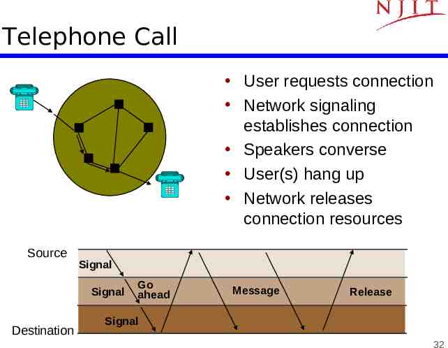
Telephone Call User requests connection Network signaling establishes connection Speakers converse User(s) hang up Network releases connection resources Source Signal Signal Destination Go ahead Message Release Signal 32
Call Routing (a) C 2 A (b) 4 Local calls routed through local network (In U.S. Local Access & Transport Area) D 3 1 5 B Long distance calls routed to long distance service provider Net 1 Net 2 LATA 1 LATA 2 33
Telephone Local Loop Local Loop: “Last Mile” Copper pair from telephone to CO Pedestal to SAI to Main Distribution Frame (MDF) 2700 cable pairs in a feeder cable MDF connects – voice signal to telephone switch – DSL signal to routers Pedestal Serving area interface Distribution frame Local telephone office Distribution cable Serving area interface Switch Feeder cable For interesting pictures of switches & MDF, see web.mit.edu/is/is/delivery/5ess/photos.html 34 www.museumofcommunications.org/coe.html
Fiber-to-the-Home or Fiber-to-the-Curve? Table 3.5 Data rates of 24-gauge twisted pair Standard Data Rate Distance T-1 1.544 Mbps 18,000 feet, 5.5 km DS2 6.312 Mbps 12,000 feet, 3.7 km 1/4 STS-1 12.960 Mbps 4500 feet, 1.4 km 1/2 STS-1 25.920 Mbps 3000 feet, 0.9 km STS-1 51.840 Mbps 1000 feet, 300 m Fiber connection to the home provides huge amount of bandwidth, but cost of optical modems still high Fiber to the curve (pedestal) with shorter distance from pedestal to home can provide high speeds over copper pairs 35
Two- & Four-wire connections From telephone to CO, two wires carry signals in both directions Inside network, 1 wire pair per direction Conversion from 2-wire to 4-wire occurs at hybrid transformer in the CO Signal reflections can occur causing speech echo Echo cancellers used to subtract the echo from the voice signals Transmit pair Original signal Four Wires Echoed signal Received signal Hybrid transformer Two Receive pair Wires 36
Note 4: Circuit-Switching Networks Signaling 37
Setting Up Connections Manually Human Intervention Telephone – Voice commands & switchboard operators Transport Networks – Order forms & dispatching of craftpersons Automatically Management Interface – Replace operators at console who set up connections at various switches Automatic signaling – Request for connection generates signaling messages that control connection setup in switches 38
Stored-Program Control (SPC) Switches SPC switches (1960s) – Crossbar switches with crossbars built from relays that open/close mechanically through electrical control – Computer program controls set up opening/closing of crosspoints to establish connections between switch inputs and outputs Signaling required to coordinate path set up across network SPC Control Signaling Message 39
Message Signaling Processors that control switches exchange signaling messages Protocols defining messages & actions defined Modems developed to communicate digitally over converted voice trunks Office A Office B Trunks Switch Processor Switch Modem Signaling Modem Processor 40
Network Intelligence Intelligent Peripherals provide additional service capabilities Voice Recognition & Voice Synthesis systems allow users to access applications via speech commands “Voice browsers” currently under development (See: www.voicexml.org) Long-term trend is for IP network to replace signaling system and provide equivalent services Services can then be provided by telephone companies as well as new types of service companies External Database SSP Signaling Network Intelligent Peripheral SSP Transport Network 41
Signaling System Protocol Stack Application layer Presentation layer TUP TCAP SCCP Network layer MTP level 3 Data link layer MTP level 2 Physical layer MTP level 1 ISUP ISDN user part SCCP signaling connection control part TUP telephone user part Session layer Transport layer ISUP Lower 3 layers ensure delivery of messages to signaling nodes SCCP allows messages to be directed to applications TCAP defines messages & protocols between applications ISUP performs basic call setup & release TUP instead of ISUP in some countries MTP message transfer part TCAP transaction capabilities part 42
Note 4: Circuit-Switching Networks Cellular Telephone Networks 43
Radio Communications 1900s: Radio telephony demonstrated 1920s: Commercial radio broadcast service 1930s: Spectrum regulation introduced to deal with interference 1940s: Mobile Telephone Service – Police & ambulance radio service – Single antenna covers transmission to mobile users in city – Less powerful car antennas transmit to network of antennas around a city – Very limited number of users can be supported 44
Cellular Communications Two basic concepts: Frequency Reuse – A region is partitioned into cells – Each cell is covered by base station – Power transmission levels controlled to minimize inter-cell interference – Spectrum can be reused in other cells Handoff – Procedures to ensure continuity of call as user moves from cell to another – Involves setting up call in new cell and tearing down old one 45
Frequency Reuse 2 7 3 1 6 4 2 5 2 7 7 3 1 6 1 6 3 4 4 5 Adjacent cells may not use same band of frequencies Frequency Reuse Pattern specifies how frequencies are reused Figure shows 7-cell reuse: frequencies divided into 7 groups & reused as shown Also 4-cell & 12-cell reuse possible Note: CDMA allows adjacent cells to use same frequencies (Chapter 6) 5 46
Cellular Network Base station Transmits to users on forward channels Receives from users on reverse channels BSS Mobile Switching Center BSS MSC HLR VLR EIR AC AC authentication center BSS base station subsystem EIR equipment identity register HLR home location register STP PSTN SS7 Wireline terminal Controls connection setup within cells & to telephone network MSC mobile switching center PSTN public switched telephone network STP signal transfer point VLR visitor location register 47
Signaling & Connection Control Setup channels set aside for call setup & handoff – Mobile unit selects setup channel with strongest signal & monitors this channel Incoming call to mobile unit – – – – – – – MSC sends call request to all BSSs BSSs broadcast request on all setup channels Mobile unit replies on reverse setup channel BSS forwards reply to MSC BSS assigns forward & reverse voice channels BSS informs mobile to use these Mobile phone rings 48
Mobile Originated Call Mobile sends request in reverse setup channel Message from mobile includes serial # and possibly authentication information BSS forwards message to MSC MSC consults Home Location Register for information about the subscriber MSC may consult Authentication center MSC establishes call to PSTN BSS assigns forward & reverse channel 49
Handoff Base station monitors signal levels from its mobiles If signal level drops below threshold, MSC notified & mobile instructed to transmit on setup channel Base stations in vicinity of mobile instructed to monitor signal from mobile on setup channel Results forward to MSC, which selects new cell Current BSS & mobile instructed to prepare for handoff MSC releases connection to first BSS and sets up connection to new BSS Mobile changes to new channels in new cell Brief interruption in connection (except for CDMA) 50
Roaming Users subscribe to roaming service to use service outside their home region Signaling network used for message exchange between home & visited network Roamer uses setup channels to register in new area MSC in visited areas requests authorization from users Home Location Register Visitor Location Register informed of new user User can now receive & place calls 51
Further Reading Textbook: 4.1, 4.4, 4.5, 4.6, 4.8 52