DC GENERATOR CHAPTER-9
81 Slides2.38 MB

DC GENERATOR CHAPTER-9
CONTENTS 1. Generator Principle, Construction & working 2. Parts of a Generator 3. EMF Equation of a Generator 4. Losses and Efficiencies in DC Generators 5. Characteristics of DC generators
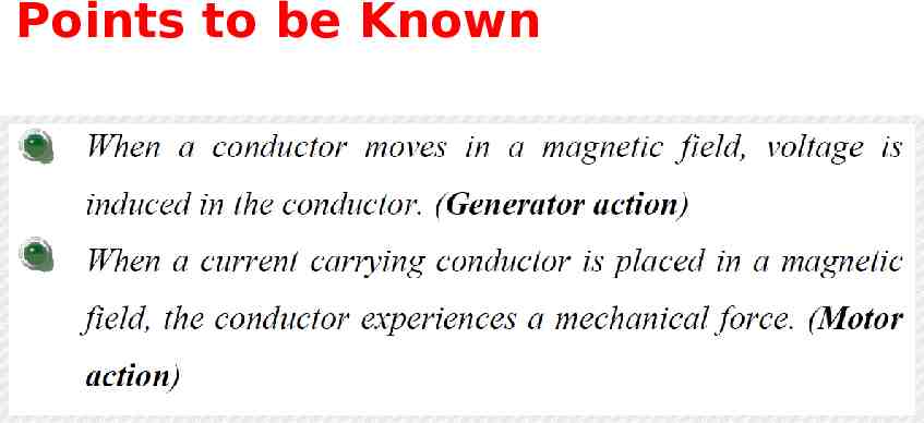
Points to be Known
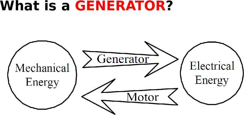
What is a GENERATOR?
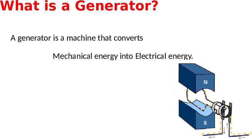
What is a Generator? A generator is a machine that converts Mechanical energy into Electrical energy.
What is an DC Generator? A DC generator is an electrical machine which converts mechanical energy into electrical energy(DC). The energy conversion is based on Faraday’s Law of Electromagnetic Induction.

Principle Faraday’s Law of Electromagnetic Induction
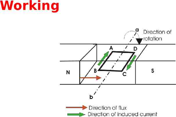
Faraday’s Law of Electromagnetic Induction According to these law, when an conductor moves in a magnetic field it cuts magnetic lines of force, due to which an emf is induced in the conductor. The magnitude of this induced emf depends upon the rate of change of flux (magnetic line force) linkage with the conductor. This emf will cause an current to flow if the conductor circuit is closed.
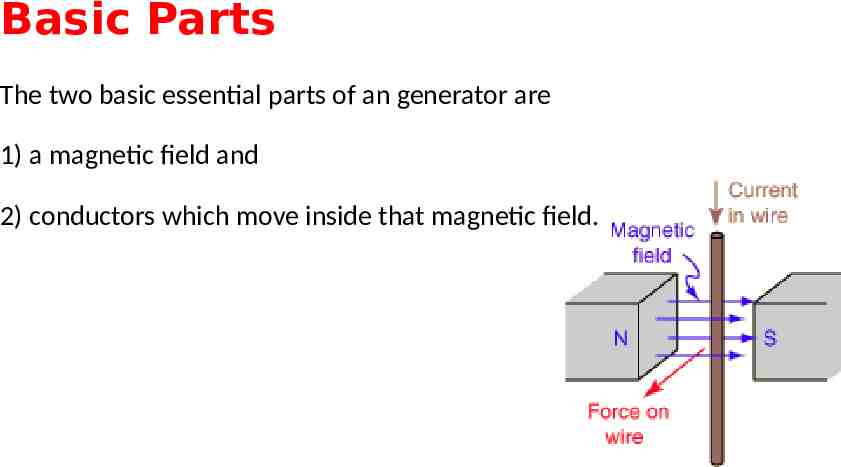
Basic Parts The two basic essential parts of an generator are 1) a magnetic field and 2) conductors which move inside that magnetic field.
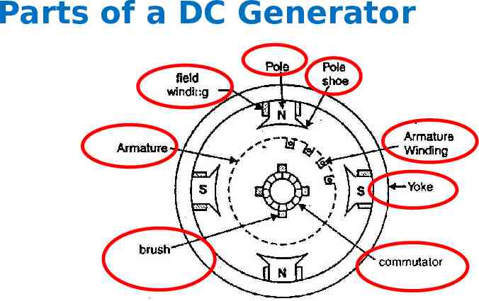
Parts of a DC Generator
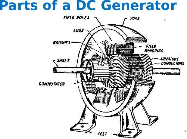
Parts of a DC Generator
Yoke The outer frame of a generator or motor is called as yoke. Yoke is made up of cast iron or steel. Yoke provides mechanical strength for whole assembly of the generator (or motor). It also carries the magnetic flux produced by the poles.
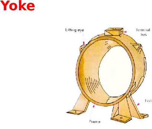
Yoke
Poles Poles are joined to the yoke with the help of screws or welding. Poles are to support field windings. Field winding is wound on poles and connected in series or parallel with armature winding or sometimes separately.

Pole Shoe Pole shoe is an extended part of the pole which serves two purposes, (1) to prevent field coils from slipping and (2) to spread out the flux in air gap uniformly.
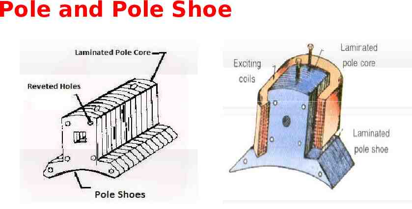
Pole and Pole Shoe
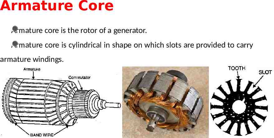
Armature Core Armature core is the rotor of a generator. Armature core is cylindrical in shape on which slots are provided to carry armature windings.
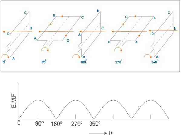
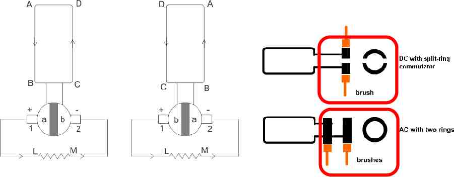
Commutator and brushes As emf is generated in the armature conductors terminals must be taken out to make use of generated emf. But if we can't directly solder wires to commutator conductors as they rotates. Thus commutator is connected to the armature conductors and mounted on the same shaft as that of armature core.
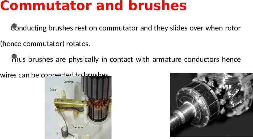
Commutator and brushes Conducting brushes rest on commutator and they slides over when rotor (hence commutator) rotates. Thus brushes are physically in contact with armature conductors hence wires can be connected to brushes.
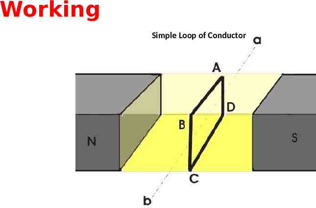
Working Simple Loop of Conductor
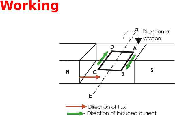
Working
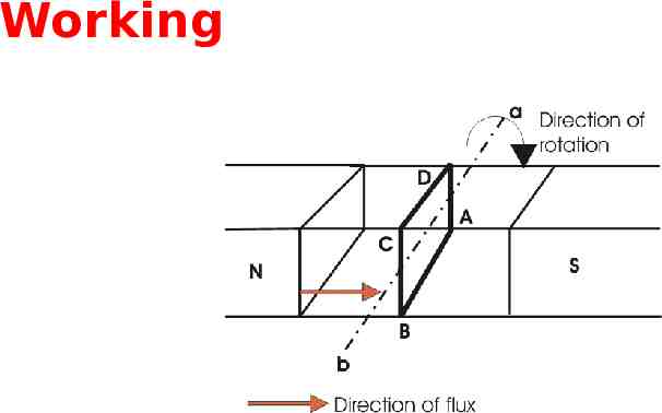
Working
Working
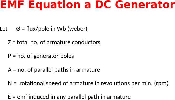
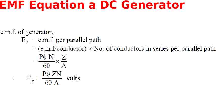
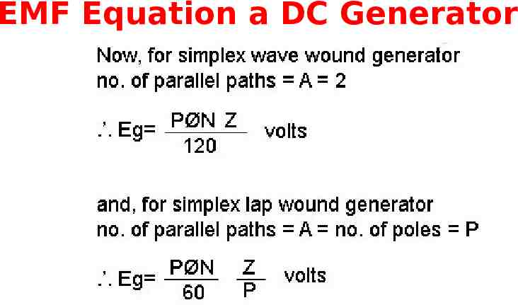
EMF Equation a DC Generator Let Ø flux/pole in Wb (weber) Z total no. of armature conductors P no. of generator poles A no. of parallel paths in armature N rotational speed of armature in revolutions per min. (rpm) E emf induced in any parallel path in armature
EMF Equation a DC Generator
EMF Equation a DC Generator volts
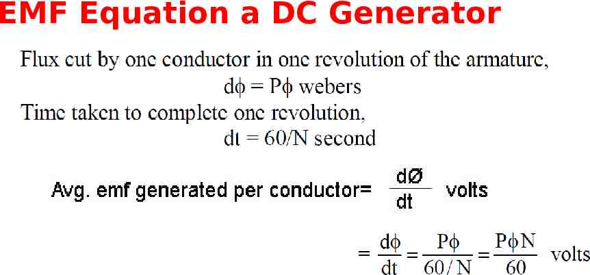
EMF Equation a DC Generator
Losses in a DC machine Copper losses 1. Armature Cu loss 2. Field Cu loss 3. Loss due to brush contact resistance Iron Losses 1. Hysteresis loss 2. Eddy current loss Mechanical losses 1. Friction losses 2. Windage losses
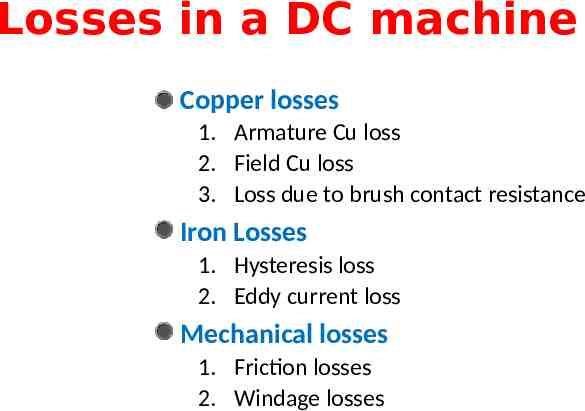
Copper losses These losses are the losses due to armature and field copper windings. Thus copper losses consists of 1. Armature copper loss, 2. Field copper loss and 3. Loss due to brush contact resistance.
Copper losses-Armature Cu Loss Armature copper loss Ia2Ra (Where Ia is Armature current and Ra is Armature resistance) This loss is about 30 to 40% of full load losses.
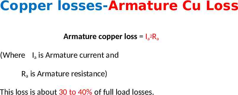
Copper losses-Field Cu Loss Field copper loss If2Rf (where If is field current and Rf is field resistance) In case of shunt wounded field, this loss is practically constant. Field copper loss is about 20 to 30% of full load losses.
Copper losses-Loss due to Brush Contact Resistance There is also brush contact loss due to brush contact resistance (i.e., resistance between the surface of brush and surface of commutator). Generally this loss is included into armature copper loss.
Iron losses (Magnetic losses) As iron core of the armature is continuously rotating in a magnetic field, there are some losses taking place in the core. Therefore iron losses are also known as Core losses. This loss consists of Hysteresis loss and Eddy current loss.
Iron losses (Magnetic losses) Hysteresis loss is due to reversal of magnetization of the armature core. When the core passes under one pair of poles, it undergoes one complete cycle of magnetic reversal. The frequency of magnetic reversal is given by, f . (where, P no. of poles and N Speed in rpm)
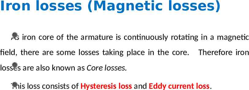
Iron losses (Magnetic losses) The loss depends upon the volume and grade of the iron, frequency of magnetic reversals and value of flux density. Hysteresis loss is given by, Steinmetz formula: Wh ηBmax1.6f V (watts) where, η Steinmetz hysteresis constant V volume of the core in m3
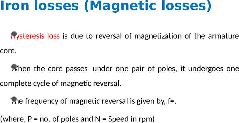
Hysteresis loss
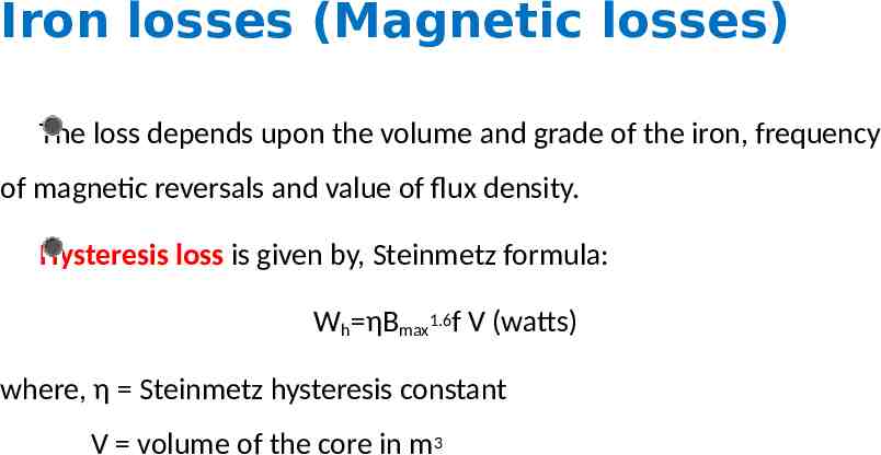
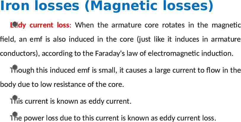
Iron losses (Magnetic losses) Eddy current loss: When the armature core rotates in the magnetic field, an emf is also induced in the core (just like it induces in armature conductors), according to the Faraday's law of electromagnetic induction. Though this induced emf is small, it causes a large current to flow in the body due to low resistance of the core. This current is known as eddy current. The power loss due to this current is known as eddy current loss.
Eddy current loss
Stray Losses Iron losses and mechanical losses together are called stray losses.
Mechanical Losses Mechanical losses consists of the losses due to friction in bearings and commutator. Air friction loss of rotating armature also contributes. These losses are about 10 to 20% of full load losses.

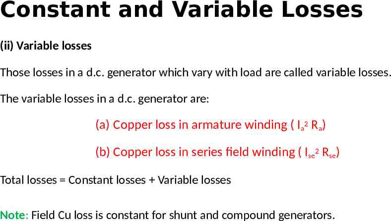
Constant and Variable Losses The losses in a d.c. generator may be sub-divided into (i) Constant losses, (ii) Variable losses. (i) Constant losses Those losses in a d.c. generator which remain constant at all loads are known as constant losses. The constant losses in a d.c. generator are: (a) iron losses (b) mechanical losses (c) shunt field losses
Constant and Variable Losses (ii) Variable losses Those losses in a d.c. generator which vary with load are called variable losses. The variable losses in a d.c. generator are: (a) Copper loss in armature winding ( Ia2 Ra) (b) Copper loss in series field winding ( Ise2 Rse) Total losses Constant losses Variable losses Note: Field Cu loss is constant for shunt and compound generators.
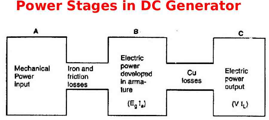
Power Stages in DC Generator
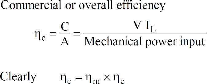
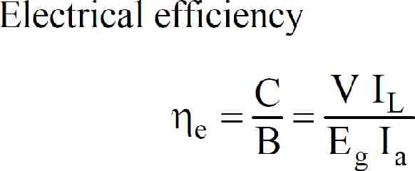
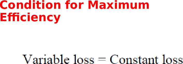
Condition for Maximum Efficiency
Characteristics of DC generator Generally, following three characteristics of DC generators are taken into considerations: (i) Open Circuit Characteristic (O.C.C.), (ii) Internal or Total Characteristic and (iii) External Characteristic.

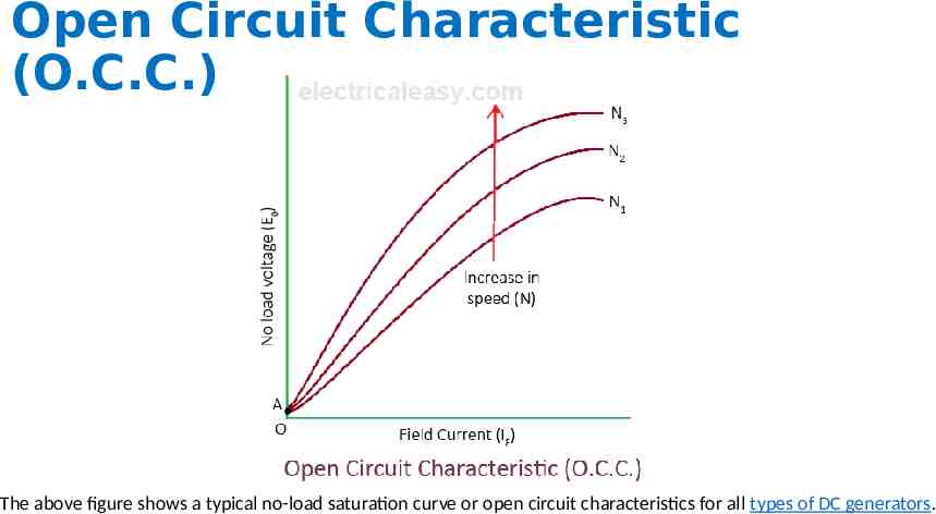
1.Open Circuit Characteristic (O.C.C.)- (E0/If) Open circuit characteristic is also known as magnetic characteristic or no-load saturation characteristic. This characteristic shows the relation between generated emf at no load (E0) and the field current (If) at the given fixed speed. The O.C.C. curve is just the magnetization curve and it is practically similar for all type of generators.
Open Circuit Characteristic (O.C.C.)- (E0/If) The data for O.C.C. curve is obtained by operating the generator at no load and keeping speed constant. Field current is varied and the corresponding terminal voltage is recorded.
Open Circuit Characteristic (O.C.C.) The above figure shows a typical no-load saturation curve or open circuit characteristics for all types of DC generators.
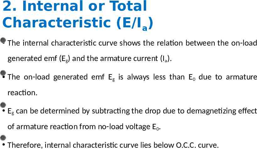
2. Internal or Total Characteristic (E/Ia) The internal characteristic curve shows the relation between the on-load generated emf (Eg) and the armature current (Ia). The on-load generated emf Eg is always less than E0 due to armature reaction. Eg can be determined by subtracting the drop due to demagnetizing effect of armature reaction from no-load voltage E0. Therefore, internal characteristic curve lies below O.C.C. curve.
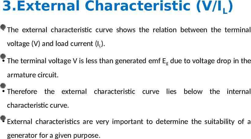
3.External Characteristic (V/IL) The external characteristic curve shows the relation between the terminal voltage (V) and load current (IL). The terminal voltage V is less than generated emf Eg due to voltage drop in the armature circuit. Therefore the external characteristic curve lies below the internal characteristic curve. External characteristics are very important to determine the suitability of a generator for a given purpose.
Characteristics of separately excited DC Generator
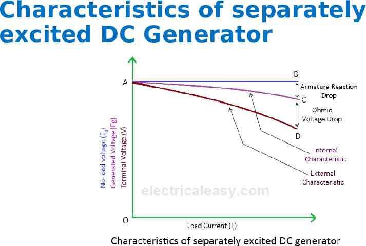
Characteristics of separately excited DC Generator If there is no armature reaction and armature voltage drop, voltage will remain constant for any load current. Thus the straight line AB in above figure represents the no-load voltage Vs. load current IL. Due to demagnetizing effect of armature reaction the on-load generated emf is less than the no-load voltage.
Characteristics of separately excited DC Generator The curve AC represents the on-load generated emf Eg vs. load current IL i.e. internal characteristic. The curve AD represents the terminal voltage vs. load current i.e. external characteristic.
Characteristics of DC Series Generator
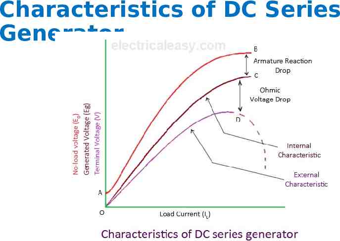
Characteristics of DC Series Generator The curve AB in above figure identical to open circuit characteristic (O.C.C.) curve. This is because, in DC series generators field winding is connected in series with armature and load. Hence, here load current is similar to field current. The curve OC and OD represents internal and external characteristic respectively.
Characteristics of DC Shunt Generator
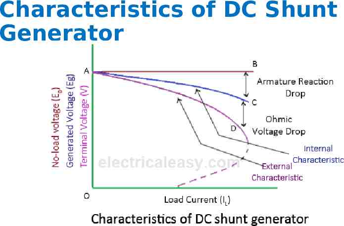
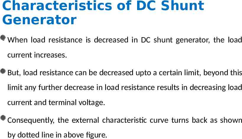
Characteristics of DC Shunt Generator When load resistance is decreased in DC shunt generator, the load current increases. But, load resistance can be decreased upto a certain limit, beyond this limit any further decrease in load resistance results in decreasing load current and terminal voltage. Consequently, the external characteristic curve turns back as shown by dotted line in above figure.
Characteristics of DC Compound Generator
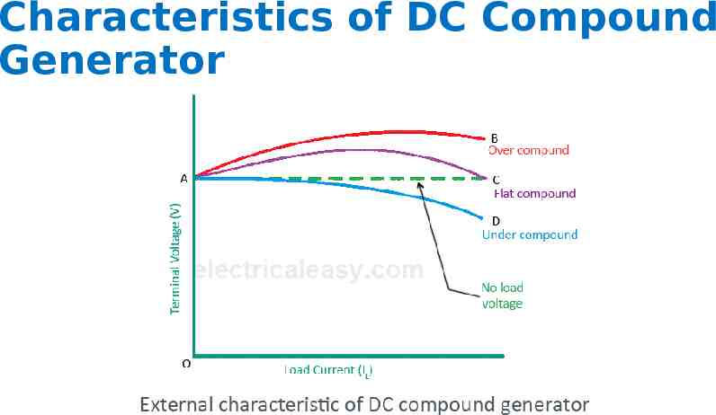
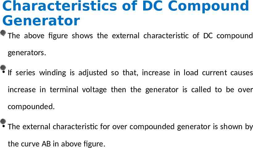
Characteristics of DC Compound Generator The above figure shows the external characteristic of DC compound generators. If series winding is adjusted so that, increase in load current causes increase in terminal voltage then the generator is called to be over compounded. The external characteristic for over compounded generator is shown by the curve AB in above figure.
Characteristics of DC Compound Generator If series winding is adjusted so that, terminal voltage remains constant even the load current is increased, then the generator is called to be flat compounded. The external characteristic for a flat compounded generator is shown by the curve AC.
Characteristics of DC Compound Generator If the series winding has lesser number of turns than that would be required to be flat compounded, then the generator is called to be under compounded. The external characteristics for an under compounded generator is shown by the curve AD.
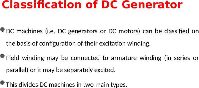
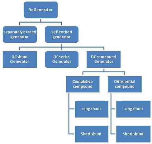
Classification of DC Generator DC machines (i.e. DC generators or DC motors) can be classified on the basis of configuration of their excitation winding. Field winding may be connected to armature winding (in series or parallel) or it may be separately excited. This divides DC machines in two main types.
Classification of DC Generator
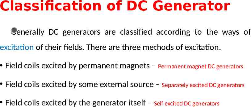
Classification of DC Generator Generally DC generators are classified according to the ways of excitation of their fields. There are three methods of excitation. Field coils excited by permanent magnets – Permanent magnet DC generators Field coils excited by some external source – Separately excited DC generators Field coils excited by the generator itself – Self excited DC generators
Permanent magnet DC generators
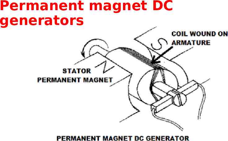
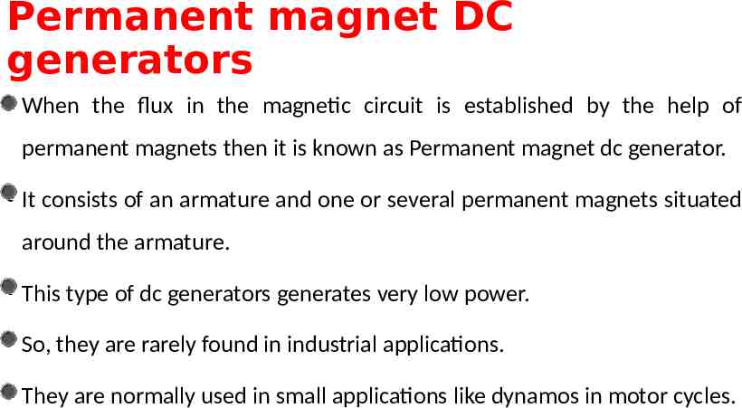
Permanent magnet DC generators When the flux in the magnetic circuit is established by the help of permanent magnets then it is known as Permanent magnet dc generator. It consists of an armature and one or several permanent magnets situated around the armature. This type of dc generators generates very low power. So, they are rarely found in industrial applications. They are normally used in small applications like dynamos in motor cycles.
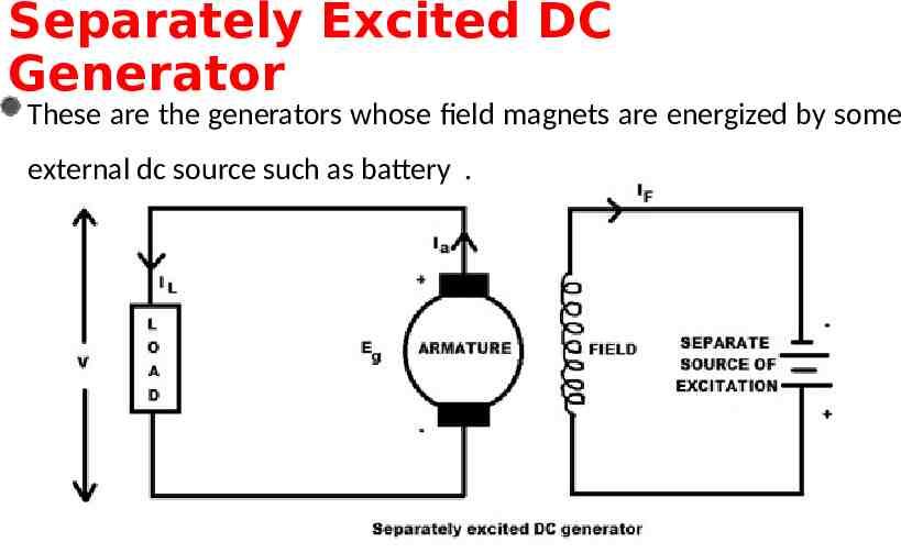
Separately Excited DC Generator These are the generators whose field magnets are energized by some external dc source such as battery .
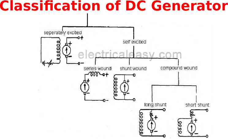
Self-excited DC Generators These are the generators whose field magnets are energized by the current supplied by themselves.
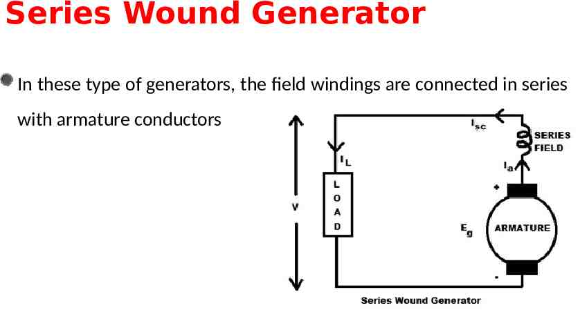
Series Wound Generator In these type of generators, the field windings are connected in series with armature conductors
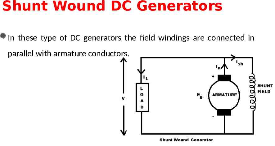
Shunt Wound DC Generators In these type of DC generators the field windings are connected in parallel with armature conductors.
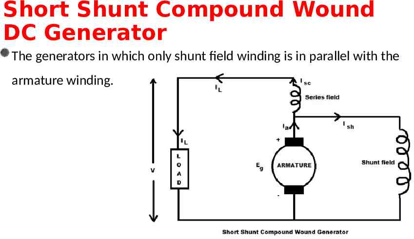
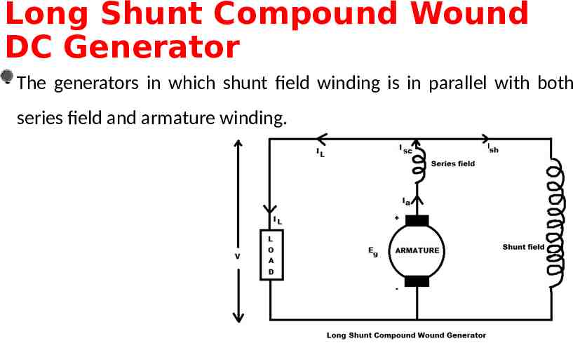
Compound wound generators Compound wound generators have both series field winding and shunt field winding. One winding is placed in series with the armature and the other is placed in parallel with the armature. This type of DC generators may be of two types- short shunt compound wound generator and long shunt compound wound generator.
Short Shunt Compound Wound DC Generator The generators in which only shunt field winding is in parallel with the armature winding.
Long Shunt Compound Wound DC Generator The generators in which shunt field winding is in parallel with both series field and armature winding.

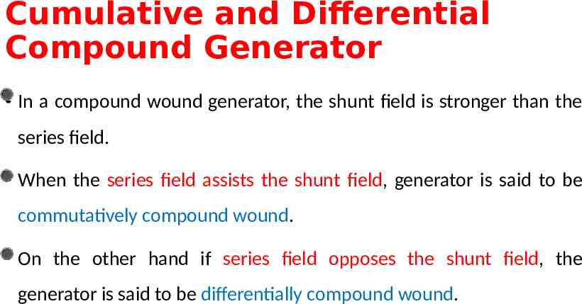
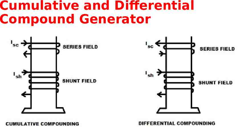
Cumulative and Differential Compound Generator In a compound wound generator, the shunt field is stronger than the series field. When the series field assists the shunt field, generator is said to be commutatively compound wound. On the other hand if series field opposes the shunt field, the generator is said to be differentially compound wound.
Cumulative and Differential Compound Generator
