City of Hope Amini Medical Center Christopher Bratz Pennsylvania State


43 Slides3.85 MB
City of Hope Amini Medical Center Christopher Bratz Pennsylvania State University Architectural Engineering Mechanical Option Faculty Advisor: Dr. Jelena Srebric
Disclaimer Due to limited information regarding the central plant, the Amini Center was removed from the central cooling plant and provided its own independent primary chilled water loop. This redesigned system serves as the baseline of comparison for my thesis depth redesign. For the remainder of this presentation, the “Existing System” refers to the Amini Center’s independent cooling plant.
Building Information Location: Durante, California (L.A. Suburb) Size: 3-Stories, 59,800 sf New Construction Occupancy: Clinic, Lab, Office, Moderate Hazard Storage Design-Bid-Build Construction Dates: 06.11.07 – 01.22.09
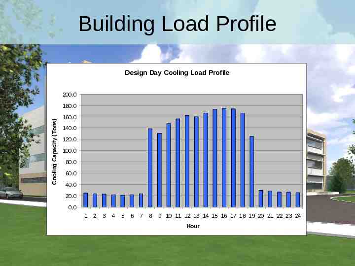
Building Load Profile Design Day Cooling Load Profile 200.0 Cooling Capacity (Tons) 180.0 160.0 140.0 120.0 100.0 80.0 60.0 40.0 20.0 0.0 1 2 3 4 5 6 7 8 9 10 11 12 13 14 15 16 17 18 19 20 21 22 23 24 Hour
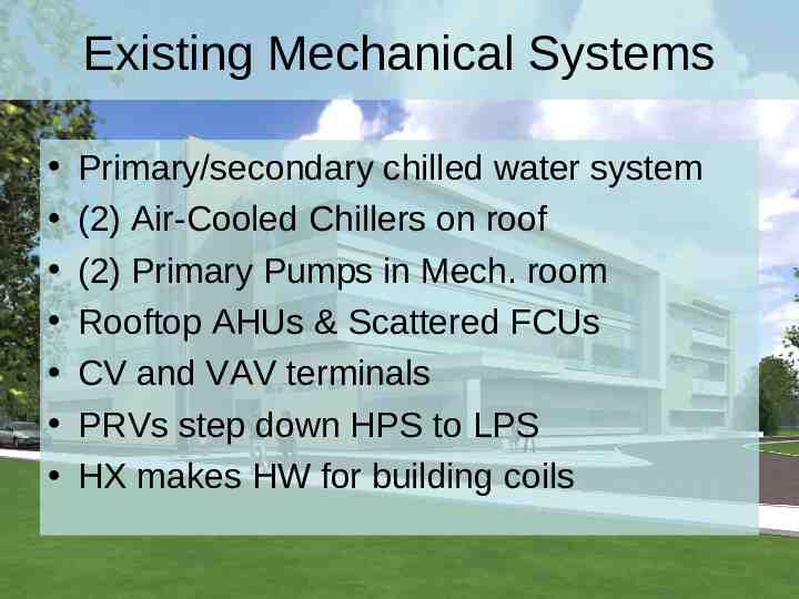
Existing Mechanical Systems Primary/secondary chilled water system (2) Air-Cooled Chillers on roof (2) Primary Pumps in Mech. room Rooftop AHUs & Scattered FCUs CV and VAV terminals PRVs step down HPS to LPS HX makes HW for building coils
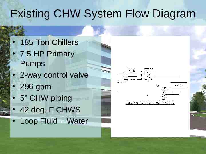
Existing CHW System Flow Diagram 185 Ton Chillers 7.5 HP Primary Pumps 2-way control valve 296 gpm 5” CHW piping 42 deg. F CHWS Loop Fluid Water
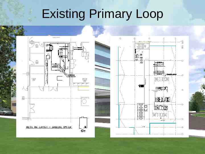
Existing Primary Loop
Annual Energy Consumption
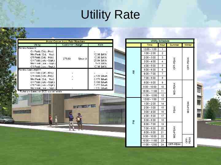
Utility Rate
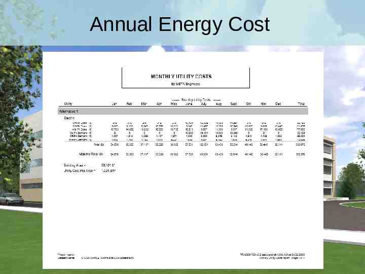
Annual Energy Cost
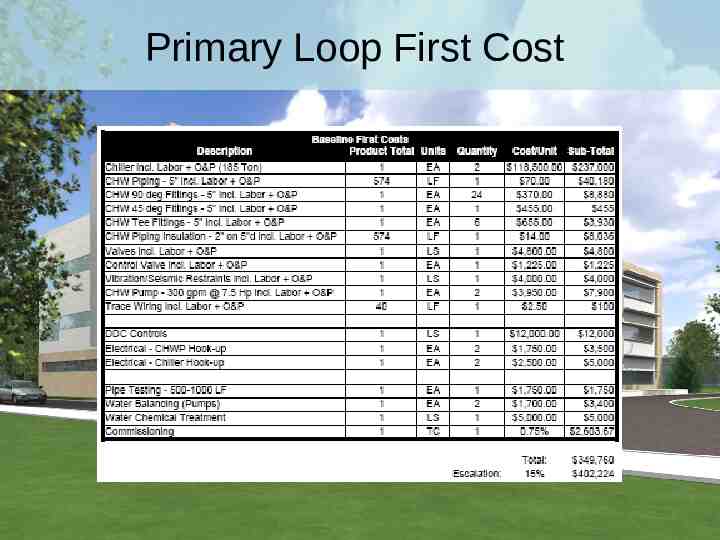
Primary Loop First Cost
Mechanical Redesign Objectives & Analyses Reduce annual energy cost Maintain reasonable first cost Reduce chiller demand load Design Ice Storage System Shift Load to off peak hours Cheaper Utility Rates
Mechanical Redesign Ice Storage System Ice making chillers & storage tanks Primary Pumps 25% Ethylene Glycol (2) 3-way modulating valves Internal melt ice-on-coil system Control Sequencing – Full Storage – Load Leveling Partial Storage – Demand Limiting Partial Storage
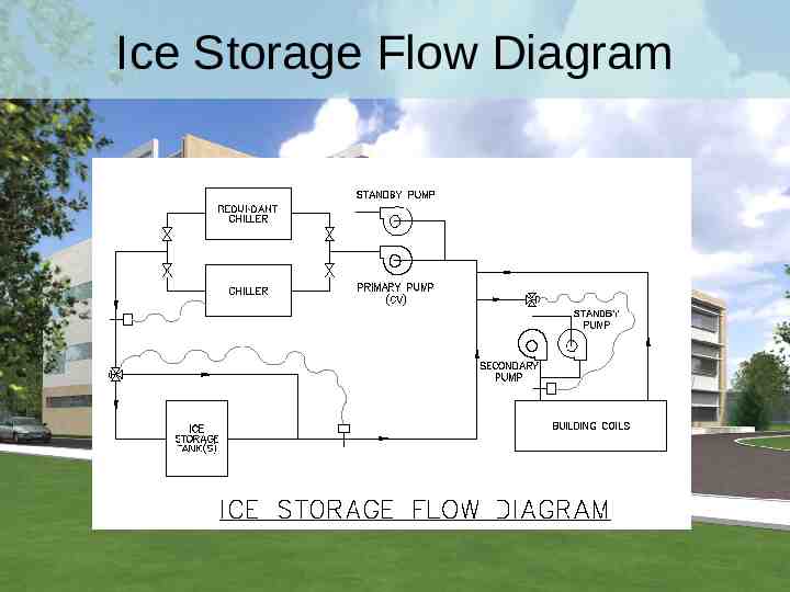
Ice Storage Flow Diagram
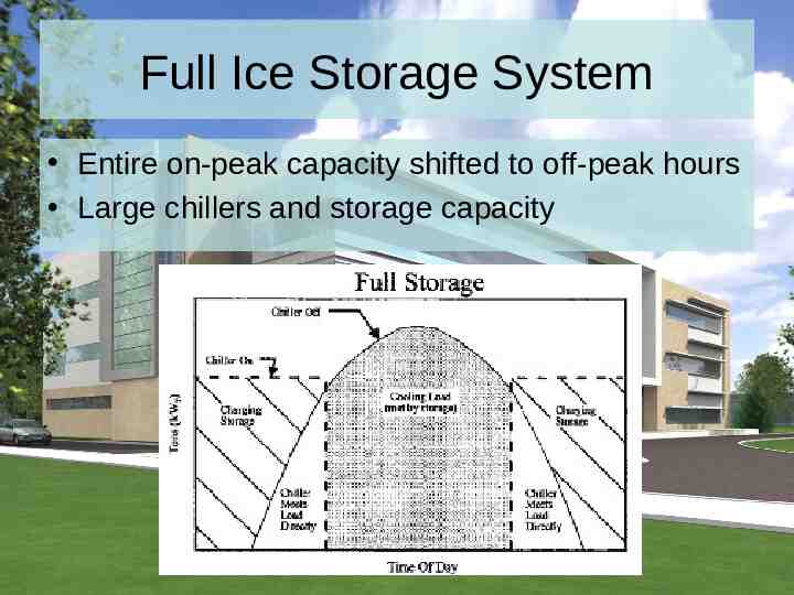
Full Ice Storage System Entire on-peak capacity shifted to off-peak hours Large chillers and storage capacity
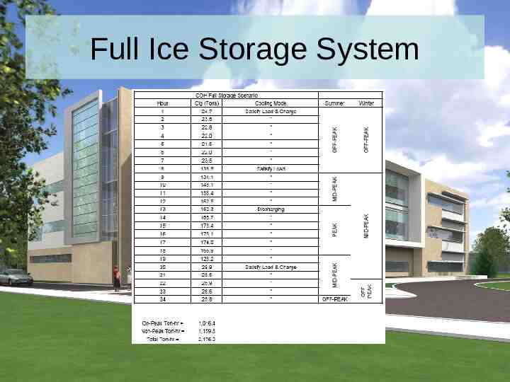
Full Ice Storage System
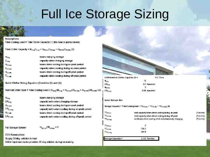
Full Ice Storage Sizing
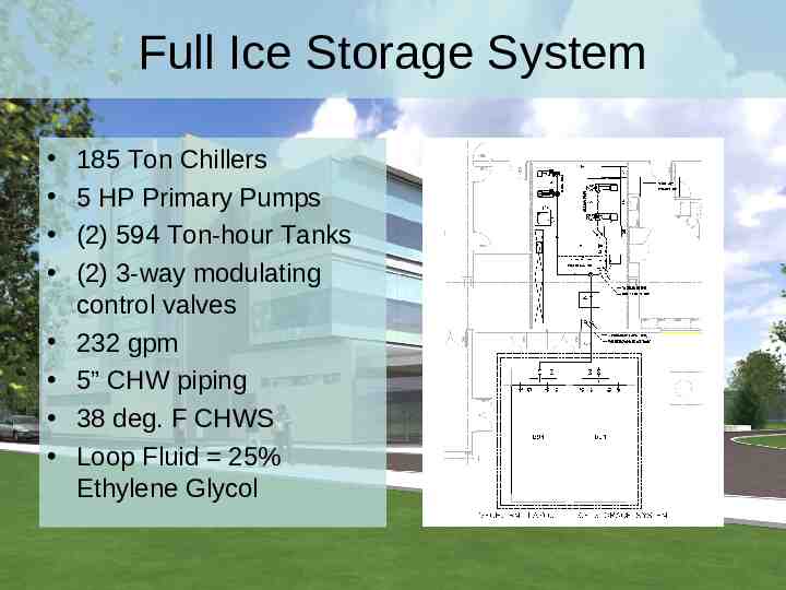
Full Ice Storage System 185 Ton Chillers 5 HP Primary Pumps (2) 594 Ton-hour Tanks (2) 3-way modulating control valves 232 gpm 5” CHW piping 38 deg. F CHWS Loop Fluid 25% Ethylene Glycol
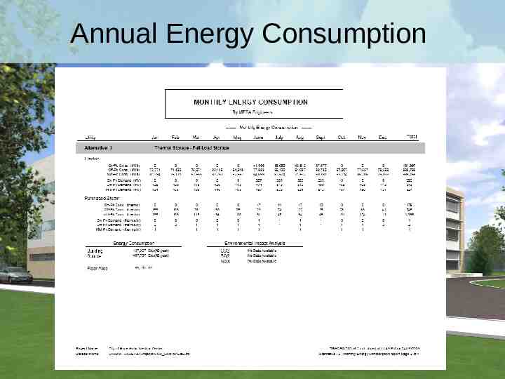
Annual Energy Consumption
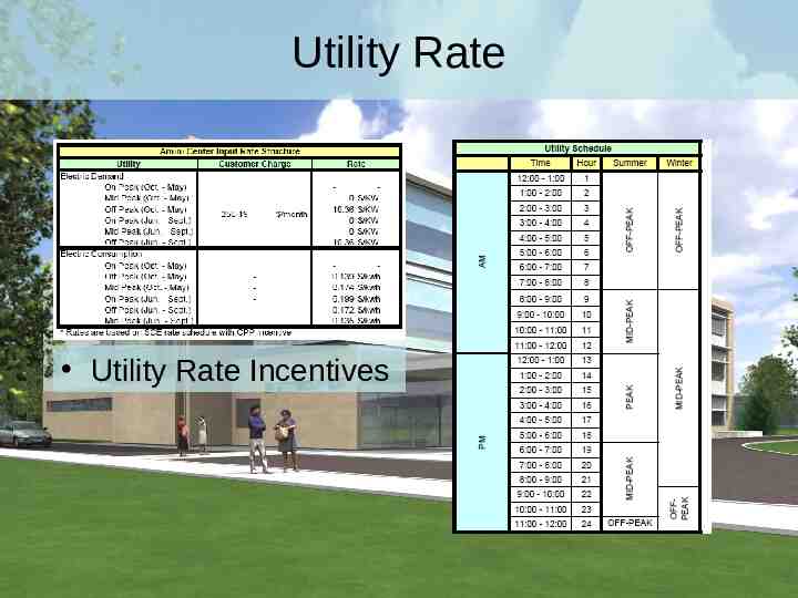
Utility Rate Utility Rate Incentives
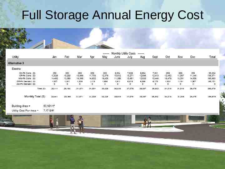
Full Storage Annual Energy Cost
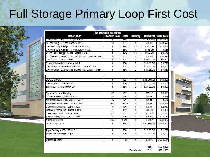
Full Storage Primary Loop First Cost
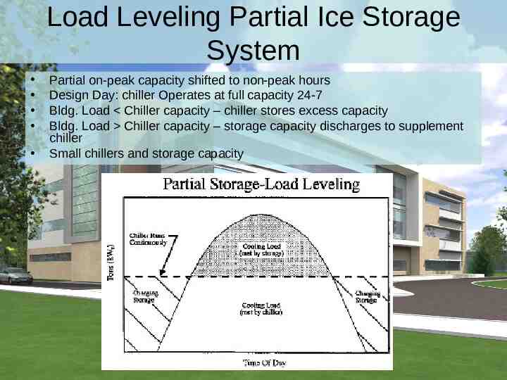
Load Leveling Partial Ice Storage System Partial on-peak capacity shifted to non-peak hours Design Day: chiller Operates at full capacity 24-7 Bldg. Load Chiller capacity – chiller stores excess capacity Bldg. Load Chiller capacity – storage capacity discharges to supplement chiller Small chillers and storage capacity
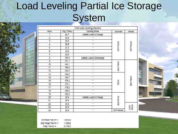
Load Leveling Partial Ice Storage System
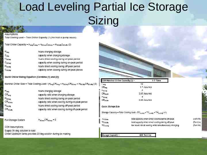
Load Leveling Partial Ice Storage Sizing
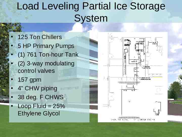
Load Leveling Partial Ice Storage System 125 Ton Chillers 5 HP Primary Pumps (1) 761 Ton-hour Tank (2) 3-way modulating control valves 157 gpm 4” CHW piping 38 deg. F CHWS Loop Fluid 25% Ethylene Glycol
Annual Energy Consumption
Utility Rate Utility Rate Incentives
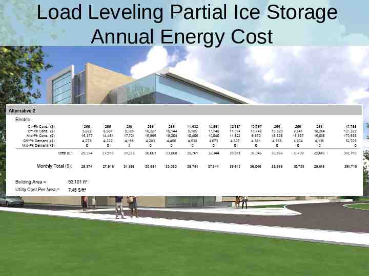
Load Leveling Partial Ice Storage Annual Energy Cost
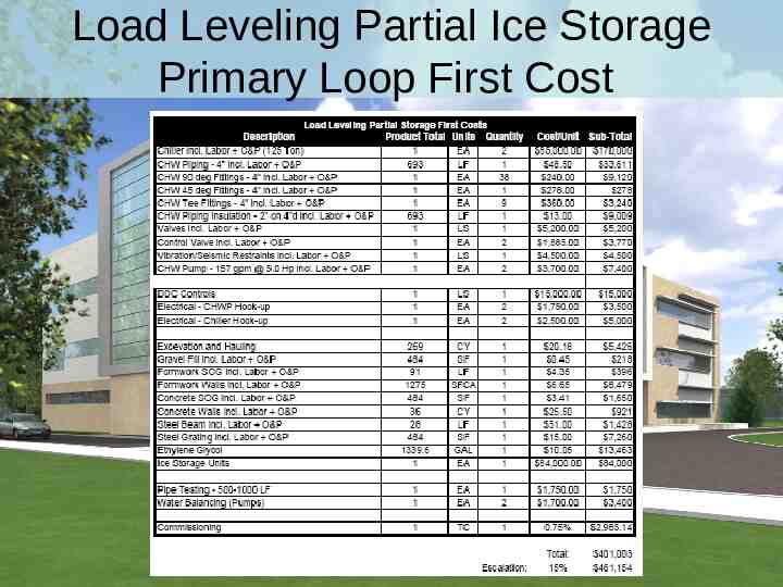
Load Leveling Partial Ice Storage Primary Loop First Cost
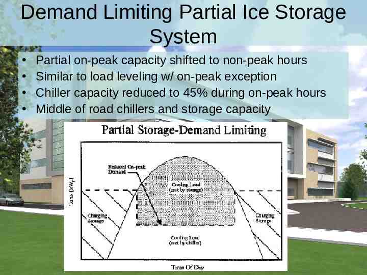
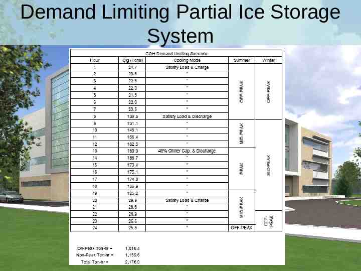
Demand Limiting Partial Ice Storage System Partial on-peak capacity shifted to non-peak hours Similar to load leveling w/ on-peak exception Chiller capacity reduced to 45% during on-peak hours Middle of road chillers and storage capacity
Demand Limiting Partial Ice Storage System
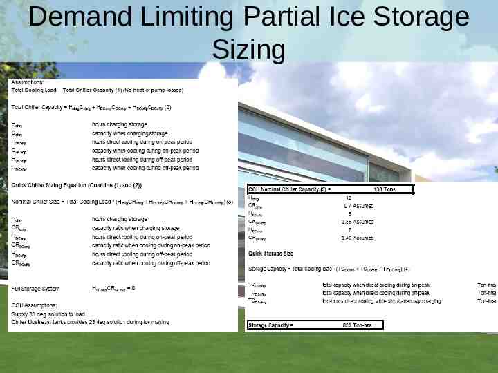
Demand Limiting Partial Ice Storage Sizing
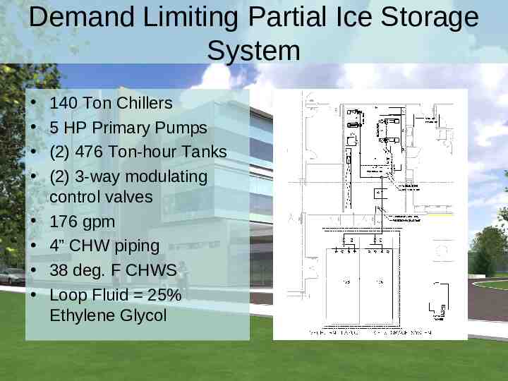
Demand Limiting Partial Ice Storage System 140 Ton Chillers 5 HP Primary Pumps (2) 476 Ton-hour Tanks (2) 3-way modulating control valves 176 gpm 4” CHW piping 38 deg. F CHWS Loop Fluid 25% Ethylene Glycol
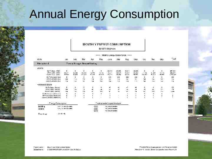
Annual Energy Consumption
Utility Rate Utility Rate Incentives
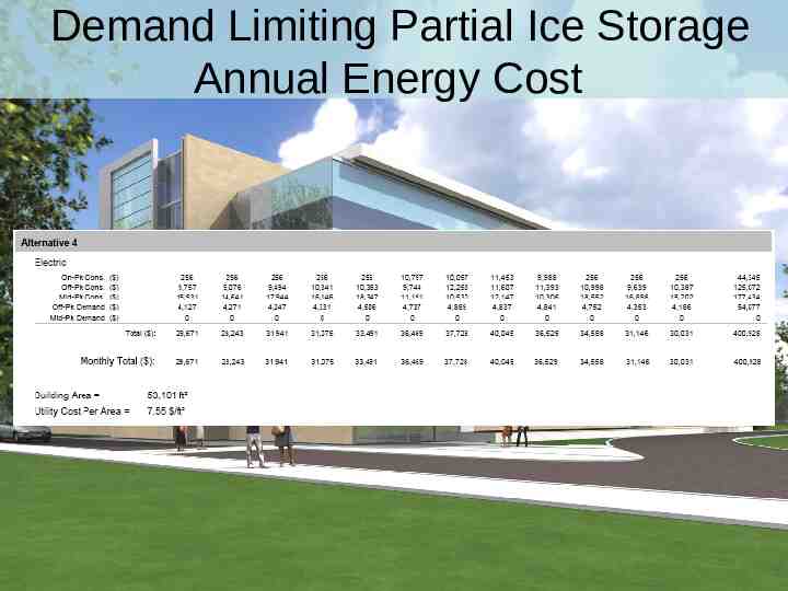
Demand Limiting Partial Ice Storage Annual Energy Cost
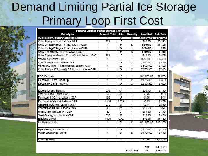
Demand Limiting Partial Ice Storage Primary Loop First Cost
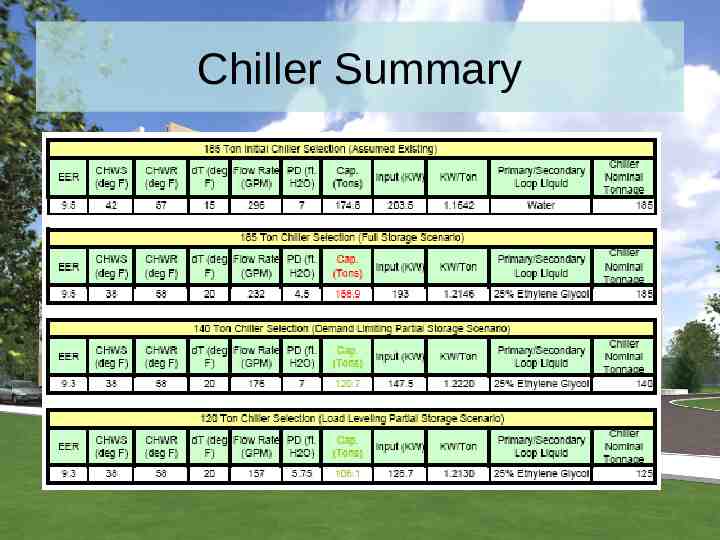
Chiller Summary
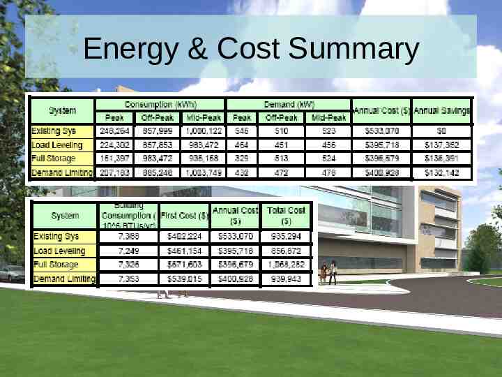
Energy & Cost Summary
Ice Storage Redesign Recommendation Load Leveling Scenario – Lowest first cost – Lowest Annual cost – Smallest Chiller and pump size – Smallest ice storage capacity – Smaller piping – Roof framing smaller
Advantages / Disadvantages Advantages – Lowest Annual cost – Smaller Chiller, pump, and piping sizes – Slight energy savings (cleaner energy offhours) – Utility Incentives – Lower CHWS Temp. Disadvantages – First cost – Physical size and weight of storage tanks – Ethylene glycol need – Increased controls and length of piping
Questions?