Chapter 7 Basic Troubleshooting and Repair Procedures MElec-Ch7 – 1


65 Slides6.73 MB
Chapter 7 Basic Troubleshooting and Repair Procedures MElec-Ch7 - 1
Overview Tools Needed Circuit Troubleshooting Electrical Interference MElec-Ch7 - 2
Tools Needed Multimeters Wiring Tools Miscellaneous Tools Do-It-Yourself Test Tools Commercial Testers MElec-Ch7 - 3
Multimeter Required features in a boat’s multimeter Measure up to 50 VDC DC voltages either 6, 12 and sometimes 24 Measure up to 250 VAC AC voltages either 120 or 240 Measure resistance or continuity Audible continuity checker is desirable Desirable features Measure AC and DC current up to 10 amps Entry level measure current to approx. 250 mA MElec-Ch7 - 4
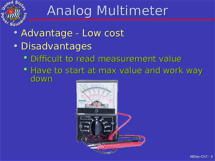
Analog Multimeter Advantage - Low cost Disadvantages Difficult to read measurement value Have to start at max value and work way down MElec-Ch7 - 5
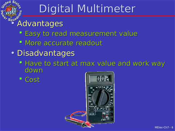
Digital Multimeter Advantages Easy to read measurement value More accurate readout Disadvantages Have to start at max value and work way down Cost MElec-Ch7 - 6
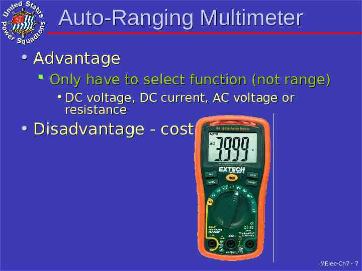
Auto-Ranging Multimeter Advantage Only have to select function (not range) DC voltage, DC current, AC voltage or resistance Disadvantage - cost MElec-Ch7 - 7
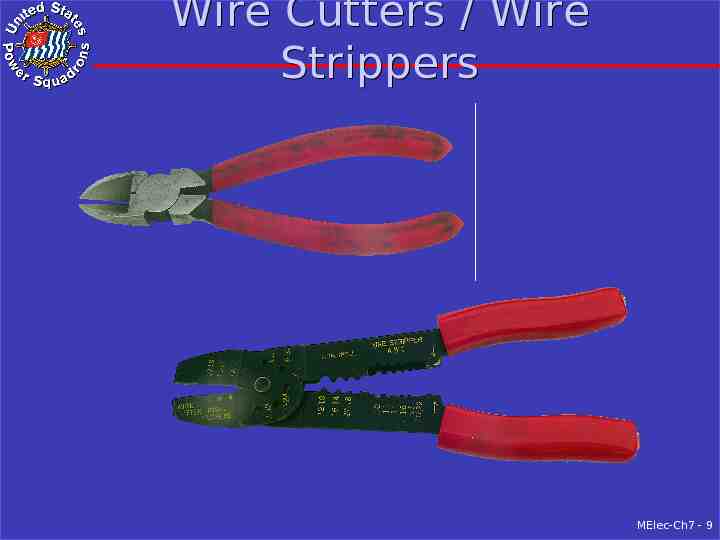
Wiring Tools Wire Cutter – Diagonal Cutter 5 or 6” overall Plastic cushion grip Wire Stripper Don’t use knife Are dedicated tools Most used – Combination Cut/Strip/Crimp Tool Not to be used as crimp tool Wire cutters at tip not effective MElec-Ch7 - 8
Wire Cutters / Wire Strippers MElec-Ch7 - 9
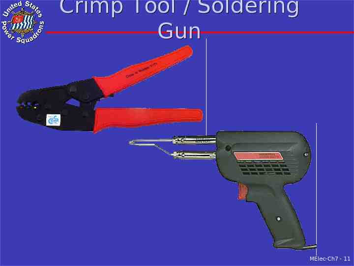
Wiring Tools - 2 Ratcheting crimp tool required by ABYC Covered in Chapter 2 Expensive compared to combination tool Soldering gun Normally boat wiring is NOT soldered Done with crimp on terminals and butt spices Required for some coax connectors Recommend dual 100/140 watt With appropriate tip will cut lines and fuse ends MElec-Ch7 - 10
Crimp Tool / Soldering Gun MElec-Ch7 - 11
Miscellaneous Tools Pliers To hold objects Not a substitute for a wrench Types Slip joint Needle nose 5” or 6” overall with plastic cushioned grips Wrench (for electrical work) Adjustable 6” MElec-Ch7 - 12
Pliers / Adjustable Wrench MElec-Ch7 - 13
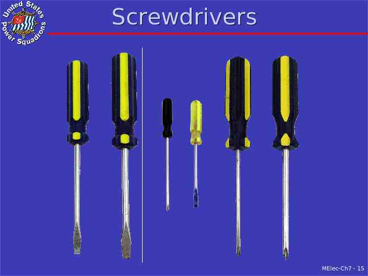
Screwdrivers Blade 3/16” blade with 4” shaft 1/4” blade with 4” shaft Phillips #1 with 4” shaft #2 with 4” shaft Small 1/8” blade with approx. 2” shaft #0 Phillips with approx. 2” shaft MElec-Ch7 - 14
Screwdrivers MElec-Ch7 - 15
Circuit Trouble-Shooting Batteries Alternators Battery Chargers Boat Lighting System Boat DC Electronic Systems Boat AC Circuits MElec-Ch7 - 16
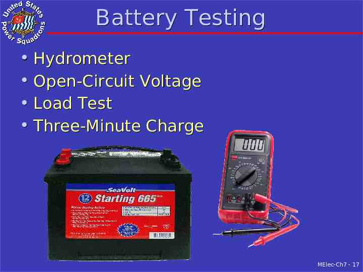
Battery Testing Hydrometer Open-Circuit Voltage Load Test Three-Minute Charge MElec-Ch7 - 17
Hydrometer Hydrometer – best tester of floodedcell Measures Specific Gravity Chapter 3, Table 5 Specific Gravity 100 % charge 1.265 75 % charge 1.225 50 % charge 1.190 25 % charge 1.155 Discharged 1.120 MElec-Ch7 - 18
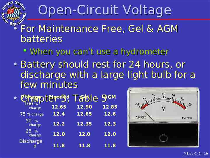
Open-Circuit Voltage For Maintenance Free, Gel & AGM batteries When you can’t use a hydrometer Battery should rest for 24 hours, or discharge with a large light bulb for a few minutes Voltage Flooded Gel AGM Chapter 3, Table 5 100 % charge 75 % charge 50 % charge 25 % charge Discharge d 12.65 12.4 12.90 12.65 12.85 12.6 12.2 12.35 12.3 12.0 12.0 12.0 11.8 11.8 11.8 MElec-Ch7 - 19
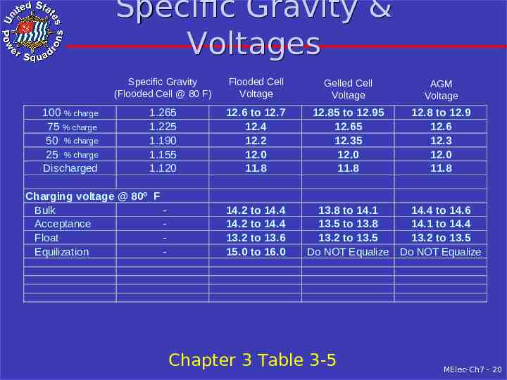
Specific Gravity & Voltages 100 % charge 75 % charge 50 % charge 25 % charge Discharged Specific Gravity (Flooded Cell @ 80 F) Flooded Cell Voltage Gelled Cell Voltage AGM Voltage 1.265 1.225 1.190 1.155 1.120 12.6 to 12.7 12.4 12.2 12.0 11.8 12.85 to 12.95 12.65 12.35 12.0 11.8 12.8 to 12.9 12.6 12.3 12.0 11.8 14.2 to 14.4 14.2 to 14.4 13.2 to 13.6 15.0 to 16.0 13.8 to 14.1 13.5 to 13.8 13.2 to 13.5 Do NOT Equalize 14.4 to 14.6 14.1 to 14.4 13.2 to 13.5 Do NOT Equalize Charging voltage @ 80º F Bulk Acceptance Float Equilization - Chapter 3 Table 3-5 MElec-Ch7 - 20
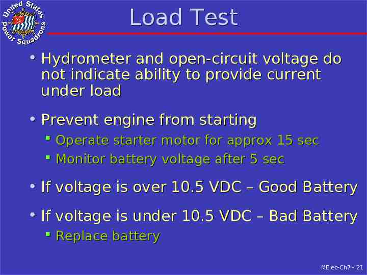
Load Test Hydrometer and open-circuit voltage do not indicate ability to provide current under load Prevent engine from starting Operate starter motor for approx 15 sec Monitor battery voltage after 5 sec If voltage is over 10.5 VDC – Good Battery If voltage is under 10.5 VDC – Bad Battery Replace battery MElec-Ch7 - 21
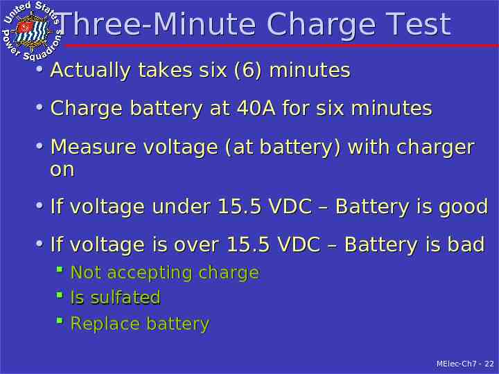
Three-Minute Charge Test Actually takes six (6) minutes Charge battery at 40A for six minutes Measure voltage (at battery) with charger on If voltage under 15.5 VDC – Battery is good If voltage is over 15.5 VDC – Battery is bad Not accepting charge Is sulfated Replace battery MElec-Ch7 - 22
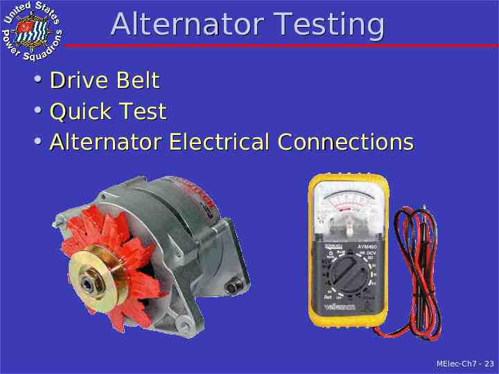
Alternator Testing Drive Belt Quick Test Alternator Electrical Connections MElec-Ch7 - 23
Drive Belt & Quick Test Drive belt Loose belt if “squealing” when engine started Belt depression when pressed at midpoint Normal (correct tightness) is only 3/8” to ½” Over ½” is too loose, tighten belt Quick test with engine & battery charger off Measure (battery) voltage at alternator Start engine and measure voltage at alternator Alternator working if voltage increases Alternator not working if voltage constant MElec-Ch7 - 24
Alternator Electrical Connections To check wiring between alternator & battery First discharge battery for five minutes Then start engine & check for high resistance connection between alternator & battery Voltage drop over 0.5 VDC needs to be fixed; or over 1.0 VDC if there are charging diodes Check both positive and negative circuit Clean and tighten the bad connection If you find a bad wire, replace it MElec-Ch7 - 25
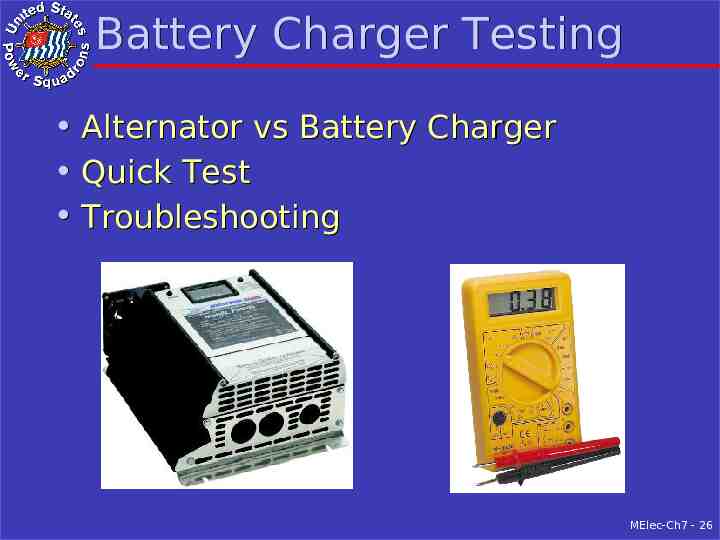
Battery Charger Testing Alternator vs Battery Charger Quick Test Troubleshooting MElec-Ch7 - 26
Alternator vs Charger & Quick Test Alternator vs Battery Charger Batteries charged by alternator Batteries not charged by battery charger Defective battery charger; see Troubleshooting Quick test with engine & charger off Measure (battery) voltage at battery charger Turn on battery charger and measure voltage Battery charger working if voltage increases Battery charger not working if voltage constant MElec-Ch7 - 27
Troubleshooting If Charger not working, check the AC input Troubleshoot like AC Circuit, covered later If there is AC input, check for a blown fuse Replace blown fuse ONCE If fuse blows a 2nd time Disconnect wire going to battery and install another fuse, then turn charger on If fuse blows again, have defective charger If fuse does NOT blow, measure DC voltage – Should be between 13 and 16 VDC MElec-Ch7 - 28
Troubleshooting - 2 Turn Charger “Off” Disconnect charger positive wire at battery Tape it to prevent wire shorting to ground Reconnect positive wire at charger Turn “On”, if fuse blows have short in wire If fuse does not blow, may have high resistance connection between charger and battery Troubleshoot wiring like you would for alternator MElec-Ch7 - 29
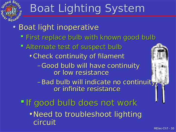
Boat Lighting System Boat light inoperative First replace bulb with known good bulb Alternate test of suspect bulb Check continuity of filament – Good bulb will have continuity or low resistance – Bad bulb will indicate no continuity or infinite resistance If good bulb does not work Need to troubleshoot lighting circuit MElec-Ch7 - 30
Lighting Troubleshooting Need a logical sequence First check circuit breakers and switches Then isolate to battery to power panel or Power panel to light MElec-Ch7 - 31
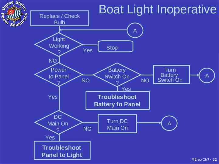
Boat Light Inoperative Replace / Check Bulb A Light Working ? Yes Stop NO Power to Panel ? NO Troubleshoot Panel to Light NO Turn Battery Switch On A Troubleshoot Battery to Panel Yes DC Main On ? Yes Battery Switch On ? Yes NO Turn DC Main On A MElec-Ch7 - 32
Battery to Power Panel No DC at battery side of DC main breaker Check/replace large fuse at battery Use multimeter Check/clean/tighten wiring Battery to battery fuse Batter fuse to power panel MElec-Ch7 - 33
Power Panel to Light Have DC at load side of branch circuit breaker Check/clean/tighten wiring at branch breaker Check/clean corrosion at light socket Use CRC QD Electronic Cleaner or equivalent Check/replace in-line fuse near light Check/replace switch in light Check wiring with temporary wires from branch circuit breaker to light fixture MElec-Ch7 - 34
Boat DC Electronic Systems 90% of equipment problems is lack of DC or bad corroded cable connections First check for power to equipment If there is power Check for blown fuse If fuse is good, there is an equipment problem Then check/clean cable connections Use CRC QD Electronic Cleaner or equivalent Lastly troubleshoot like a lighting system Previously covered MElec-Ch7 - 35
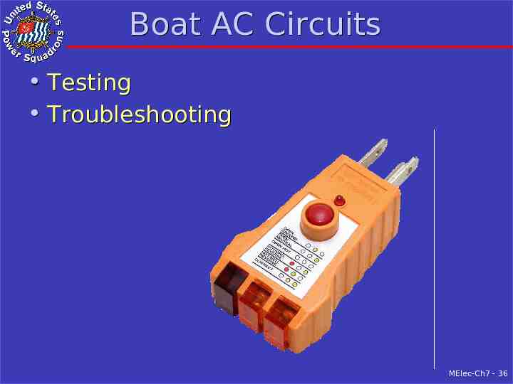
Boat AC Circuits Testing Troubleshooting MElec-Ch7 - 36
Testing AC Circuits Shore power polarity Verify correct with Reverse Polarity Indicator Outlets When first installed and once a year Verify with AC Outlet Tester GFCI outlets When first installed and once a year Insert AC Outlet Tester Press “Test” – tester lights should go “Off” Press “Reset” – tester lights should go “On” MElec-Ch7 - 37
Testing Hard Wired Appliances Turn on appropriate branch circuit breaker and Appliance “On” switch Appliance should work or Expose the AC terminal strip Use multimeter Check for AC voltage and polarity If have AC input and won’t work Defective MElec-Ch7 - 38
Troubleshooting AC Circuits Need logical sequence First check circuit breakers and switches Then isolate to dock to power panel or Power panel to outlet or appliance MElec-Ch7 - 39
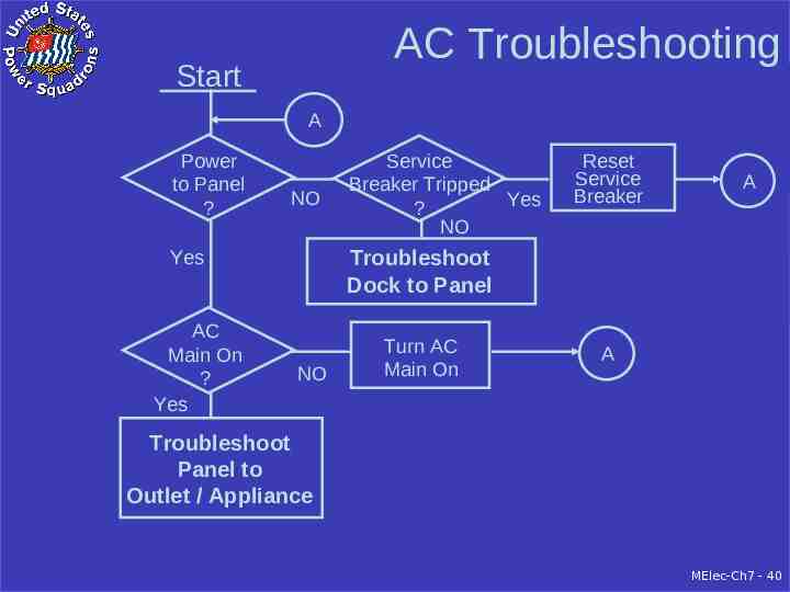
AC Troubleshooting Start A Power to Panel ? NO Reset Service Breaker A Troubleshoot Dock to Panel Yes AC Main On ? Yes Service Breaker Tripped Yes ? NO NO Turn AC Main On A Troubleshoot Panel to Outlet / Appliance MElec-Ch7 - 40
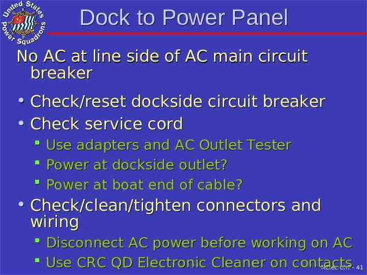
Dock to Power Panel No AC at line side of AC main circuit breaker Check/reset dockside circuit breaker Check service cord Use adapters and AC Outlet Tester Power at dockside outlet? Power at boat end of cable? Check/clean/tighten connectors and wiring Disconnect AC power before working on AC Use CRC QD Electronic Cleaner on contacts MElec-Ch7 - 41
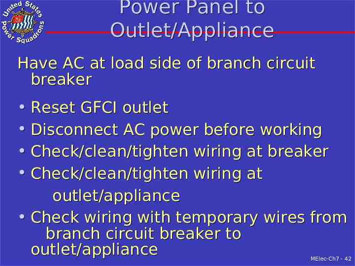
Power Panel to Outlet/Appliance Have AC at load side of branch circuit breaker Reset GFCI outlet Disconnect AC power before working Check/clean/tighten wiring at breaker Check/clean/tighten wiring at outlet/appliance Check wiring with temporary wires from branch circuit breaker to outlet/appliance MElec-Ch7 - 42
Summary – Circuit Troubleshooting DC Battery tests: Voltage, Load and 3-minute charge Alternator tests: Drive belt, quick test and wiring Battery Charger: Quick test, AC power and wiring Inoperative lights: Bulb, bulb contacts and wiring DC electronics: Verify DC power & clean contacts DC wiring: Start at power panel and isolate AC Test outlets yearly AC appliances: Verify AC power and check wiring AC wiring: Start at power panel and isolate MElec-Ch7 - 43
Electrical Interference Introduction Sources of Interference Locating Interference Sources Interference Suppression Mitigation Techniques MElec-Ch7 - 44
Introduction Causes and Effects Caused by rapid on/off current switching Radiated through air Conducted though wiring Degrades high sensitivity electronic equipment Noise Layers Usually have interference from several sources Remove/reduce till acceptable Difficult to identify stronger interference MElec-Ch7 - 45
Sources of Interference Ignition Systems Charging Systems Voltage Regulators Electric Motors Gauges and Instruments Propeller Shaft(s) Video Displays Electronic Equipment Fluorescent Lights MElec-Ch7 - 46
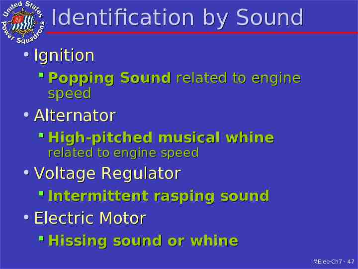
Identification by Sound Ignition Popping Sound related to engine speed Alternator High-pitched musical whine related to engine speed Voltage Regulator Intermittent rasping sound Electric Motor Hissing sound or whine MElec-Ch7 - 47
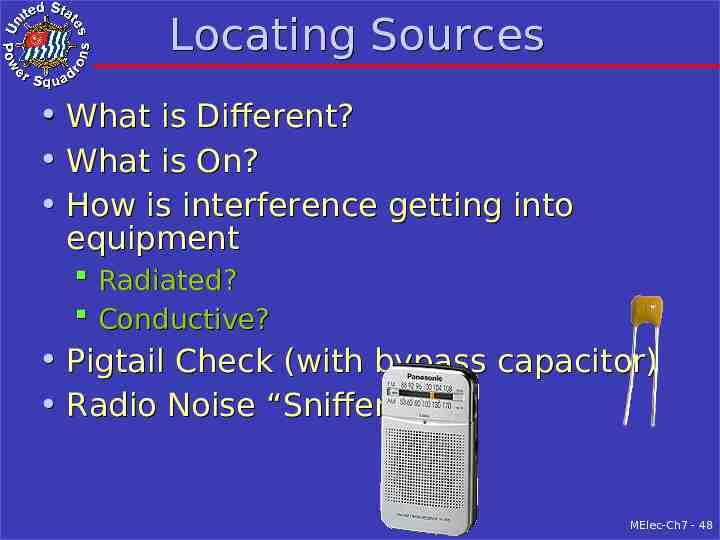
Locating Sources What is Different? What is On? How is interference getting into equipment Radiated? Conductive? Pigtail Check (with bypass capacitor) Radio Noise “Sniffer” MElec-Ch7 - 48
Interference Suppression At source of interference Approaches Repair or replace faulty equipment Shielding to confine interference Special-purpose components to reduce interference MElec-Ch7 - 49
General Suppression Replace/repair faulty equipment Correct defective wiring Bonding straps still connected? Check wiring for loose connections Re-run wiring Separate power and signal wires/cables Dress regulator field wire close to the alternator Shielding Wires Compartments with grounded copper screen MElec-Ch7 - 50
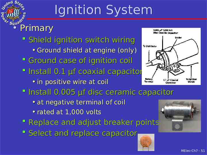
Ignition System Primary Shield ignition switch wiring Ground shield at engine (only) Ground case of ignition coil Install 0.1 µf coaxial capacitor in positive wire at coil Install 0.005 µf disc ceramic capacitor at negative terminal of coil rated at 1,000 volts Replace and adjust breaker points Select and replace capacitor MElec-Ch7 - 51
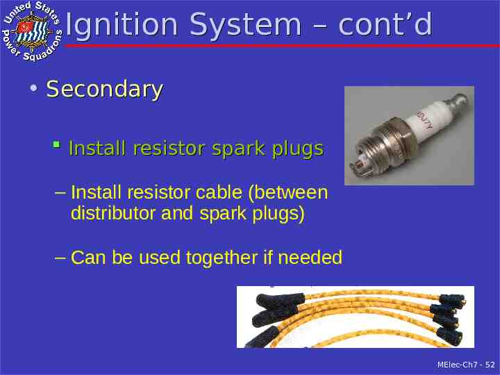
Ignition System – cont’d Secondary Install resistor spark plugs – Install resistor cable (between distributor and spark plugs) – Can be used together if needed MElec-Ch7 - 52
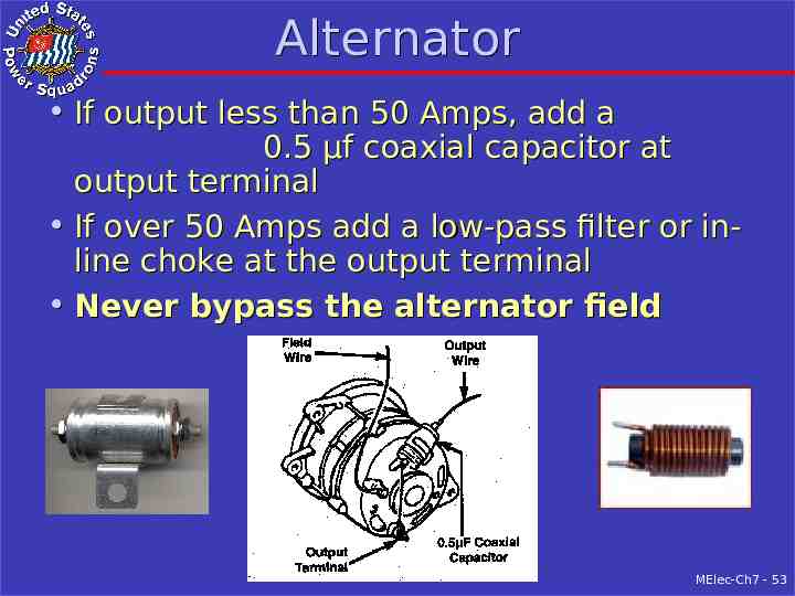
Alternator If output less than 50 Amps, add a 0.5 µf coaxial capacitor at output terminal If over 50 Amps add a low-pass filter or inline choke at the output terminal Never bypass the alternator field MElec-Ch7 - 53
Charger / Voltage Regulator Battery charger Install near battery and away from electronics Suppression built in by manufacturer Home-made copper wire shield Voltage regulator May be built in to alternator If external Mount close to alternator Consider shielding field wire (ground both ends) MElec-Ch7 - 54
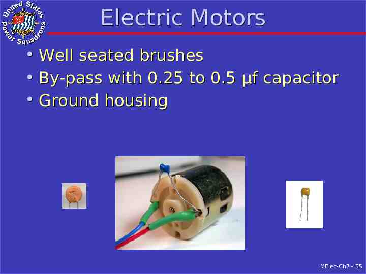
Electric Motors Well seated brushes By-pass with 0.25 to 0.5 µf capacitor Ground housing MElec-Ch7 - 55
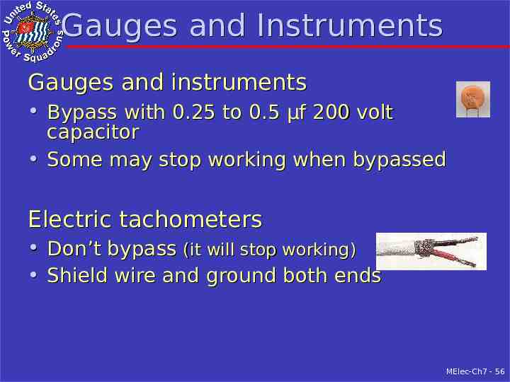
Gauges and Instruments Gauges and instruments Bypass with 0.25 to 0.5 µf 200 volt capacitor Some may stop working when bypassed Electric tachometers Don’t bypass (it will stop working) Shield wire and ground both ends MElec-Ch7 - 56
Propeller Hash Shaft Hash – Indicates stray current or galvanic current problem If possible fix problem – Best to ground the shaft with carbon brushes – Fixes the symptom, not the problem MElec-Ch7 - 57
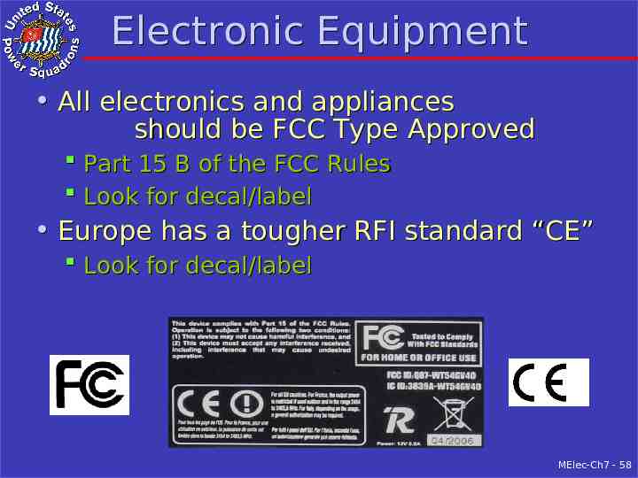
Electronic Equipment All electronics and appliances should be FCC Type Approved Part 15 B of the FCC Rules Look for decal/label Europe has a tougher RFI standard “CE” Look for decal/label MElec-Ch7 - 58
Mitigation Techniques At equipment being interfered with Approaches Shielding against radiated interference Filtering against conductive interference Capacitors (or condensers) Chokes (or inductors) MElec-Ch7 - 59
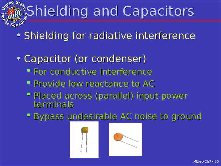
Shielding and Capacitors Shielding for radiative interference Capacitor (or condenser) For conductive interference Provide low reactance to AC Placed across (parallel) input power terminals Bypass undesirable AC noise to ground MElec-Ch7 - 60
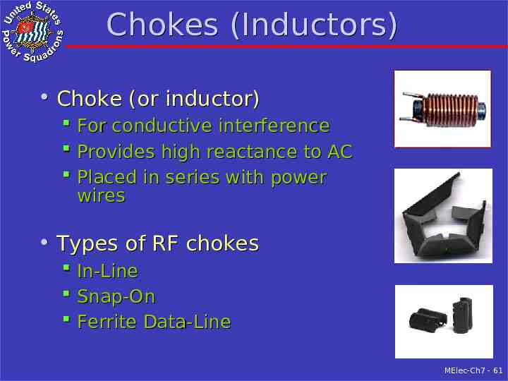
Chokes (Inductors) Choke (or inductor) For conductive interference Provides high reactance to AC Placed in series with power wires Types of RF chokes In-Line Snap-On Ferrite Data-Line MElec-Ch7 - 61
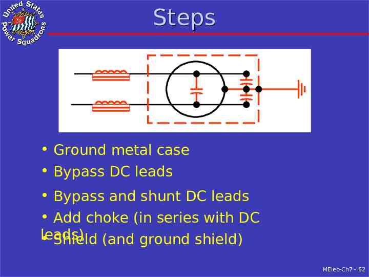
Steps Ground metal case Bypass DC leads Bypass and shunt DC leads Add choke (in series with DC leads) Shield (and ground shield) MElec-Ch7 - 62
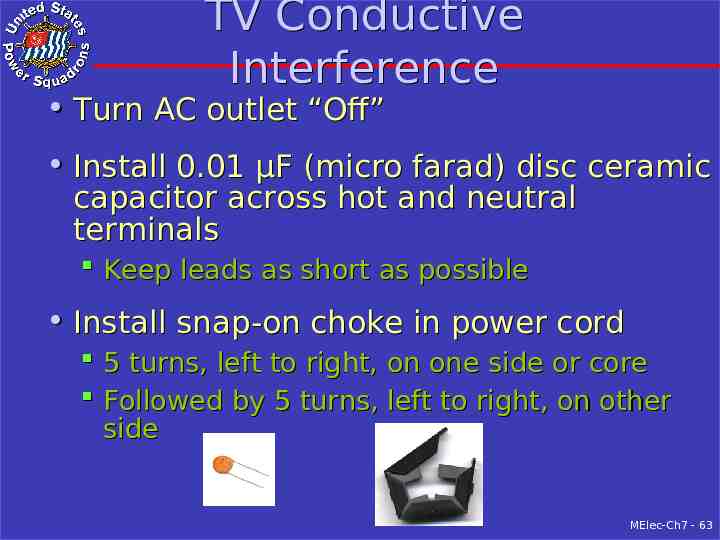
TV Conductive Interference Turn AC outlet “Off” Install 0.01 µF (micro farad) disc ceramic capacitor across hot and neutral terminals Keep leads as short as possible Install snap-on choke in power cord 5 turns, left to right, on one side or core Followed by 5 turns, left to right, on other side MElec-Ch7 - 63
Summary - Interference Locating source By its sound What is different? What is on? By use of “sniffer” Interference suppression (at source of interference) Equipment repair Specific at equipment Shielding of equipment MElec-Ch7 - 64
Summary – Interference 2 New electronics and appliances should be FCC and/or CE Type Approved Mitigation Techniques (at interfered-with equipment) Shielding Filtering MElec-Ch7 - 65