A Novel Control Scheme for a Doubly-Fed Induction Wind Generator


38 Slides2.63 MB
A Novel Control Scheme for a Doubly-Fed Induction Wind Generator Under Unbalanced Grid Voltage Conditions Ted Brekken, Ph.D. Assistant Professor in Energy Systems Oregon State University
Outline Wind Energy Overview Research Objectives DFIG Overview DFIG Control Unbalance and Induction Machines DFIG Unbalance Compensation Hardware Results
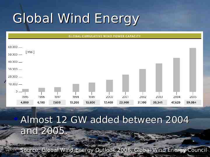
Global Wind Energy Almost 12 GW added between 2004 and 2005. Source: Global Wind Energy Outlook 2006, Global Wind Energy Council
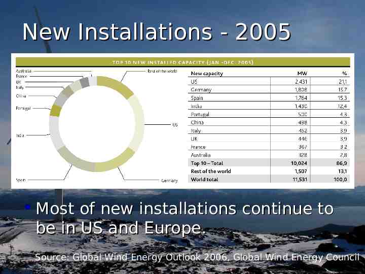
New Installations - 2005 Most of new installations continue to be in US and Europe. Source: Global Wind Energy Outlook 2006, Global Wind Energy Council
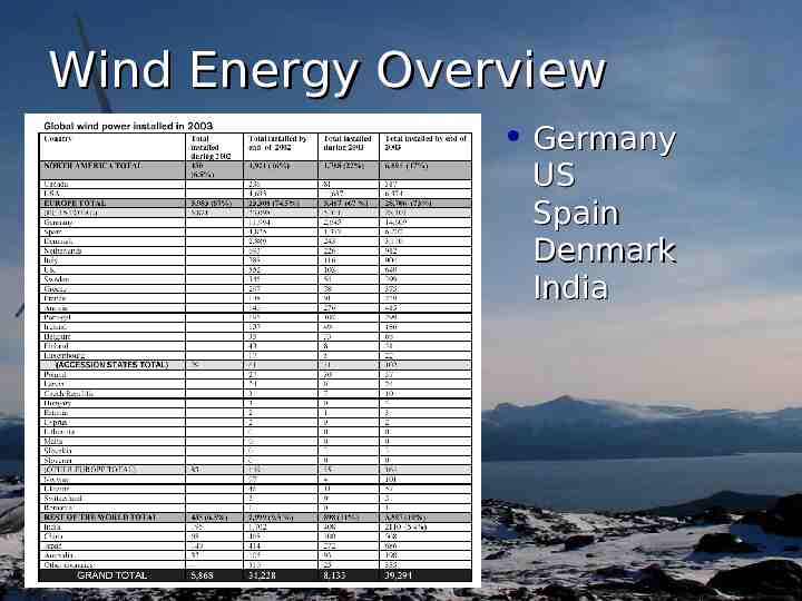
Wind Energy Overview Germany US Spain Denmark India
US Installed Projects Because of slow Midwest growth, the US still has huge potential. Source: American Wind Energy Association, www.awea.org/projects
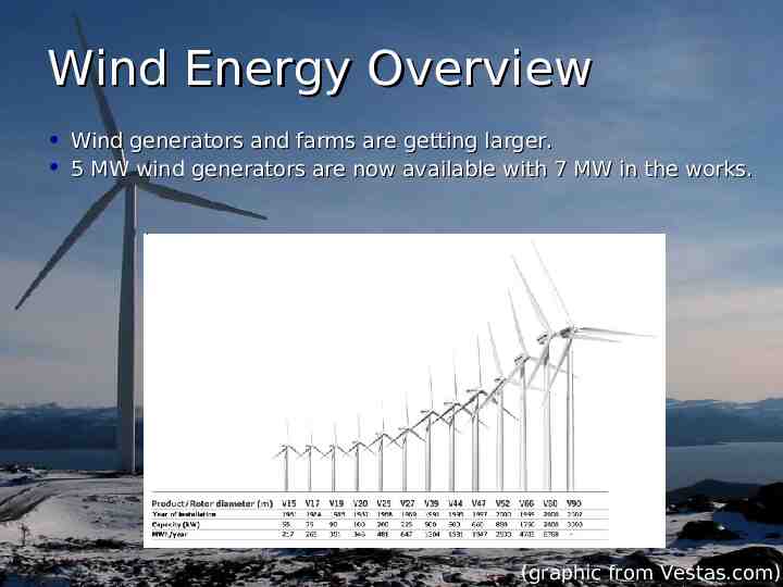
Wind Energy Overview Wind generators and farms are getting larger. 5 MW wind generators are now available with 7 MW in the works. (graphic from Vestas.com)
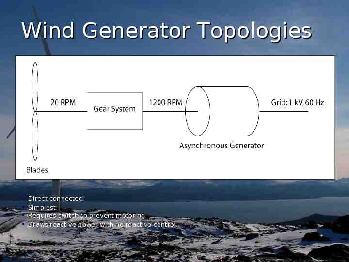
Wind Generator Topologies Direct connected. Simplest. Requires switch to prevent motoring. Draws reactive power with no reactive control.
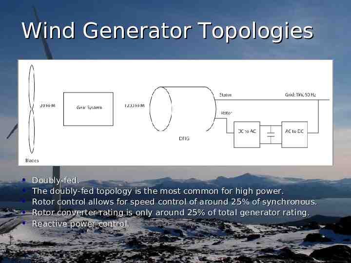
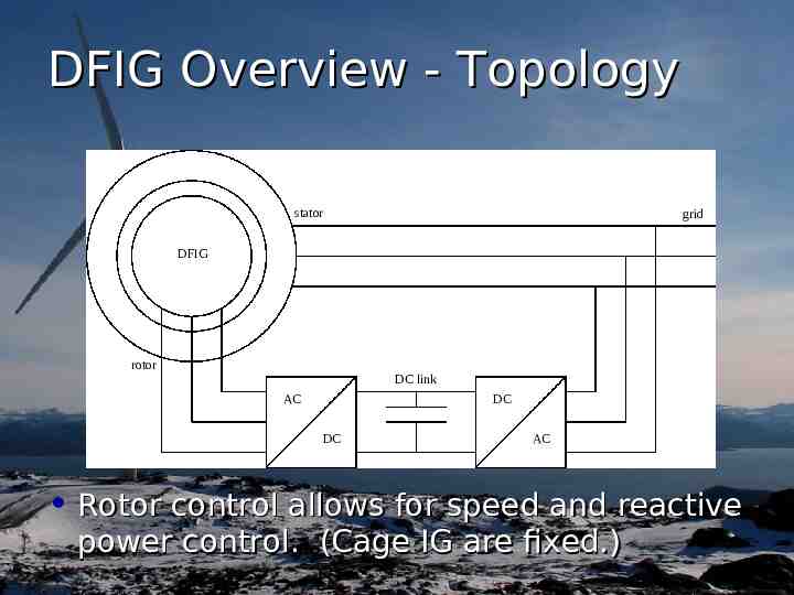
Wind Generator Topologies Doubly-fed. The doubly-fed topology is the most common for high power. Rotor control allows for speed control of around 25% of synchronous. Rotor converter rating is only around 25% of total generator rating. Reactive power control.
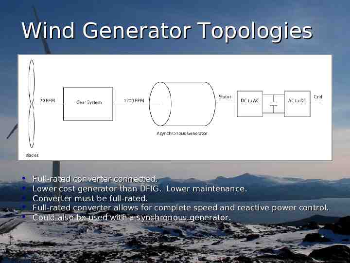
Wind Generator Topologies Full-rated converter connected. Lower cost generator than DFIG. Lower maintenance. Converter must be full-rated. Full-rated converter allows for complete speed and reactive power control. Could also be used with a synchronous generator.
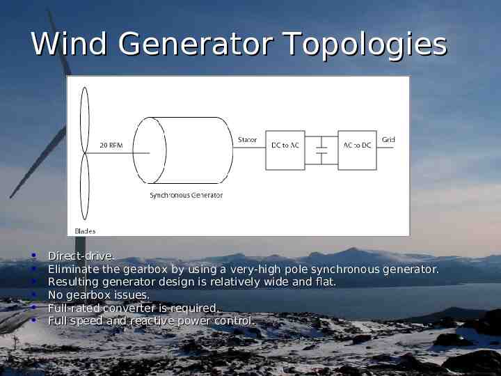
Wind Generator Topologies Direct-drive. Eliminate the gearbox by using a very-high pole synchronous generator. Resulting generator design is relatively wide and flat. No gearbox issues. Full-rated converter is required. Full speed and reactive power control.
Wind Energy Issues Wind is intermittent – Limits wind’s percentage of the energy mix Wind energy is often located in rural areas – Rural grids are often weak and unstable, and prone to voltage sags, faults, and unbalances Unbalanced grid voltages cause many problems for induction generators – Torque pulsations – Reactive power pulsations – Unbalanced currents
Outline Wind Energy Overview Research Objectives DFIG Overview DFIG Control Unbalance and Induction Machines DFIG Unbalance Compensation Hardware Results
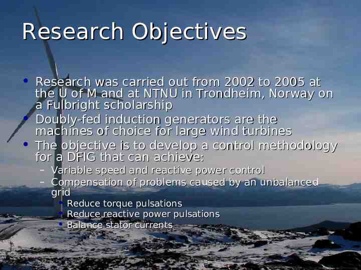
Research Objectives Research was carried out from 2002 to 2005 at the U of M and at NTNU in Trondheim, Norway on a Fulbright scholarship Doubly-fed induction generators are the machines of choice for large wind turbines The objective is to develop a control methodology for a DFIG that can achieve: – – Variable speed and reactive power control Compensation of problems caused by an unbalanced grid Reduce torque pulsations Reduce reactive power pulsations Balance stator currents
Outline Wind Energy Overview Research Objectives DFIG Overview DFIG Control Unbalance and Induction Machines DFIG Unbalance Compensation Hardware Results
DFIG Overview - Topology stator grid DFIG rotor DC link AC DC DC AC Rotor control allows for speed and reactive power control. (Cage IG are fixed.)
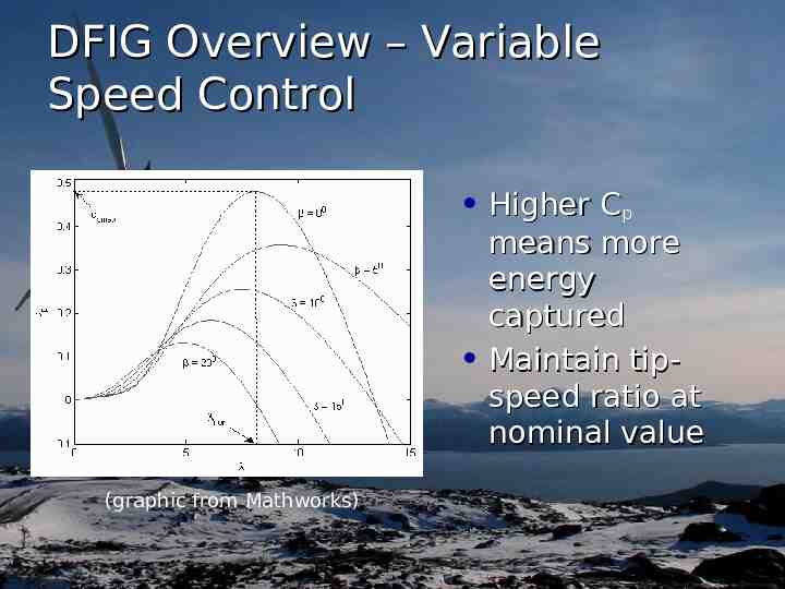
DFIG Overview – Variable Speed Control Higher Cp means more energy captured Maintain tipspeed ratio at nominal value (graphic from Mathworks)
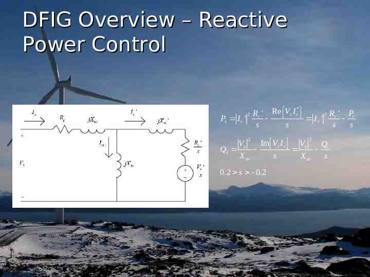
DFIG Overview – Reactive Power Control * Rr ' Re Vr I r P 2 R ' Ps I r ' Ir ' r r s s s s 2 Qs Vs 2 Xm Im Vr I r 0.2 s 0.2 s Vs 2 Xm Qr s
Outline Wind Energy Overview Research Objectives DFIG Overview DFIG Control Unbalance and Induction Machines DFIG Unbalance Compensation Simulation Results Hardware Results
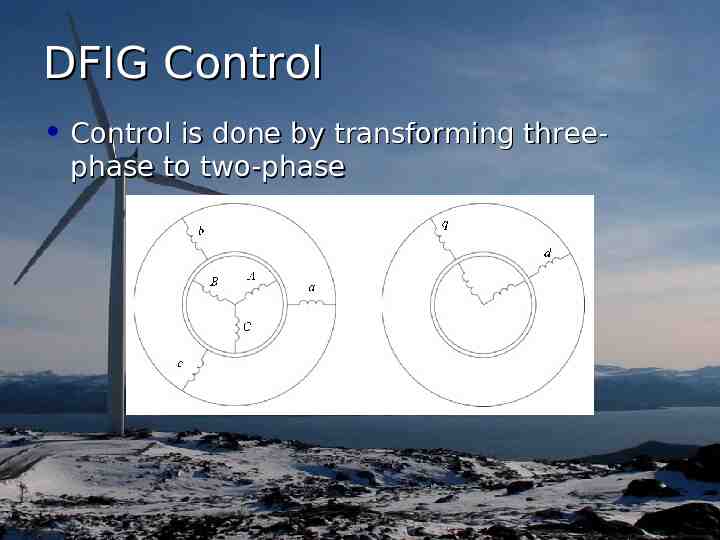
DFIG Control Control is done by transforming threephase to two-phase
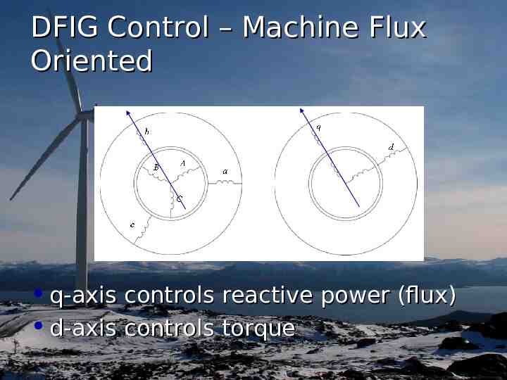
DFIG Control – Machine Flux Oriented q-axis controls reactive power (flux) d-axis controls torque
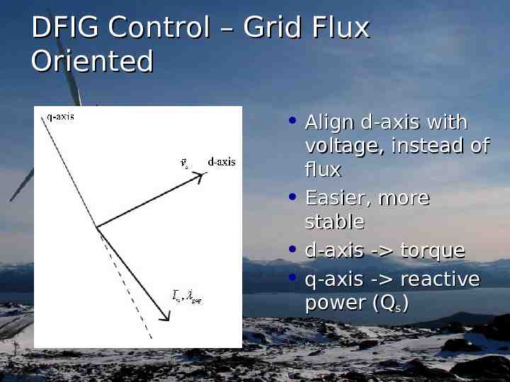
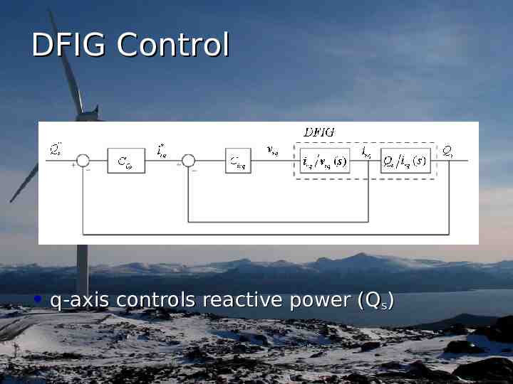
DFIG Control – Grid Flux Oriented Align d-axis with voltage, instead of flux Easier, more stable d-axis - torque q-axis - reactive power (Qs)
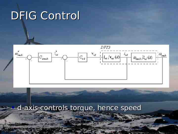
DFIG Control d-axis controls torque, hence speed
DFIG Control q-axis controls reactive power (Qs)
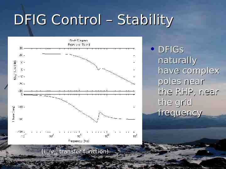
DFIG Control – Stability DFIGs naturally have complex poles near the RHP, near the grid frequency (ird/vrd transfer function)
Outline Wind Energy Overview Research Objectives DFIG Overview DFIG Control Unbalance and Induction Machines DFIG Unbalance Compensation Hardware Results
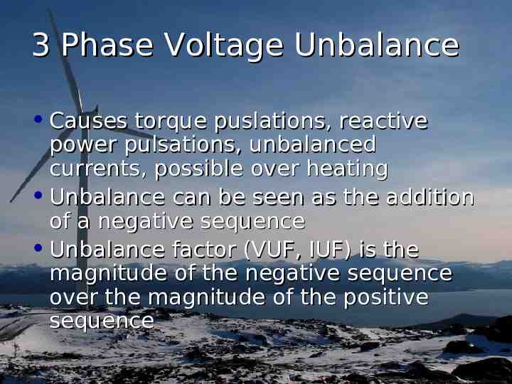
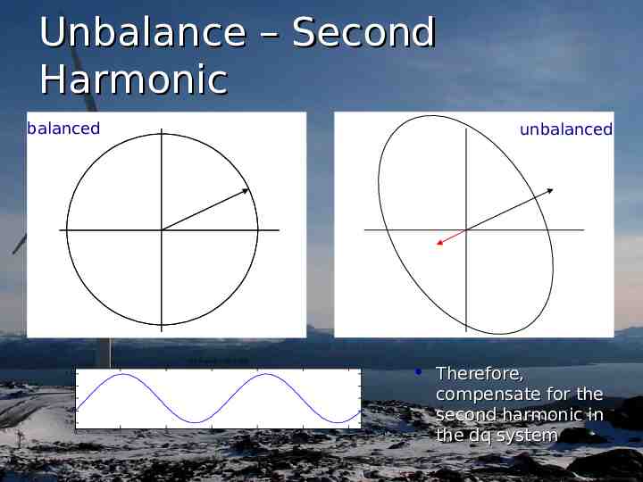
3 Phase Voltage Unbalance Causes torque puslations, reactive power pulsations, unbalanced currents, possible over heating Unbalance can be seen as the addition of a negative sequence Unbalance factor (VUF, IUF) is the magnitude of the negative sequence over the magnitude of the positive sequence
Unbalance – Second Harmonic balanced unbalanced 1 0.2 sin(2 x-30 /180) Therefore, 1.2 1.1 1 0.9 0.8 0 1 2 3 4 x 5 6 compensate for the second harmonic in the dq system
Outline Wind Energy Overview Research Objectives DFIG Overview DFIG Control Unbalance and Induction Machines DFIG Unbalance Compensation Hardware Results
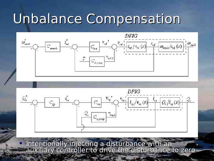
Unbalance Compensation Intentionally injecting a disturbance with an auxiliary controller to drive the disturbance to zero
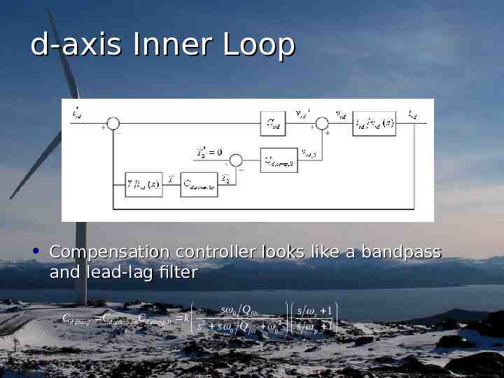
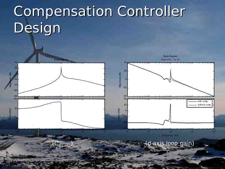
d-axis Inner Loop Compensation controller looks like a bandpass and lead-lag filter s z 1 s 0 Q filt Cd ,comp Cd ,comp ,bpCd ,comp ,ll k 2 s s Q 2 s 1 0 filt 0 p
Compensation Controller Design Bode Diagram From: In(1) To: ird Bode Diagram 40 40 20 Magnitude (dB) Magnitude (dB) 20 0 -20 -40 0 -20 -60 -80 180 -40 90 w ith comp 90 Phase (deg) Phase (deg) 45 0 w ithout comp 0 -45 -90 -90 10 -135 0 10 1 10 2 Frequency (Hz) (Cd,comp) 10 3 10 4 10 0 10 1 10 2 10 3 Frequency (Hz) (d-axis loop gain) 10 4
Outline Wind Energy Overview Research Objectives DFIG Overview DFIG Control Unbalance and Induction Machines DFIG Unbalance Compensation Hardware Results
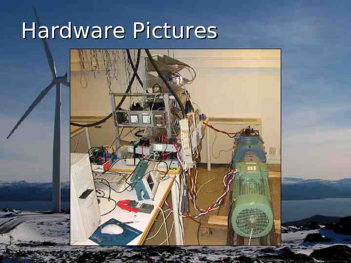
Hardware Pictures
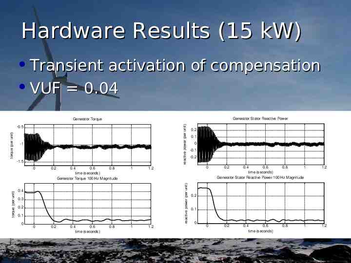
Hardware Results (15 kW) Transient activation of compensation VUF 0.04 Generator Stator Reactive Power reactive power (per unit) Generator Torque torque (per unit) -0.5 -1 -1.5 0.2 0.4 0.6 0.8 time (seconds) Generator Torque 100 Hz Magnitude 1 0.4 0.3 0.2 0.1 0 0 0.2 0.4 0.6 time (seconds) 0.8 1 0.1 0 -0.1 -0.2 0 1.2 reactive power (per unit) torque (per unit) 0 0.2 1.2 0.2 0.4 0.6 0.8 1 time (seconds) Generator Stator Reactive Power 100 Hz Magnitude 1.2 0.2 0.1 0 0 0.2 0.4 0.6 time (seconds) 0.8 1 1.2
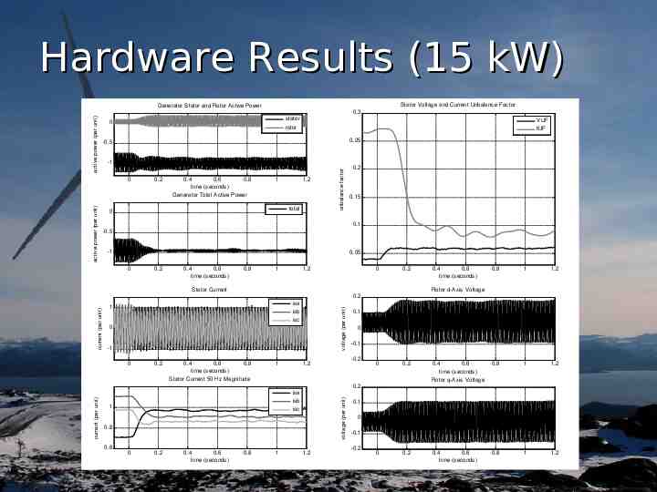
Hardware Results (15 kW) Stator Voltage and Current Unbalance Factor Generator Stator and Rotor Active Power stator rotor 0 0.25 -0.5 -1 0 active power (per unit) VUF IUF 0.2 0.4 0.6 0.8 time (seconds) Generator Total Active Power 1 1.2 total 0 unbalance factor active power (per unit) 0.3 0.2 0.15 0.1 -0.5 -1 0.05 0 0.2 0.4 0.6 time (seconds) 0.8 1 1.2 0 0.2 Stator Current 0.4 0.6 time (seconds) 0.8 1 1.2 Rotor d-Axis Voltage 1 voltage (per unit) current (per unit) 0.2 isa isb isc 0 -1 0 0.2 0.4 0.6 0.8 time (seconds) Stator Current 50 Hz Magnitude 1 0.1 0 -0.1 -0.2 1.2 0 0.2 0.4 0.6 time (seconds) Rotor q-Axis Voltage 0.8 1 1.2 0 0.2 0.4 0.6 time (seconds) 0.8 1 1.2 1 voltage (per unit) current (per unit) 0.2 isa isb isc 0.8 0.6 0 0.2 0.4 0.6 time (seconds) 0.8 1 1.2 0.1 0 -0.1 -0.2
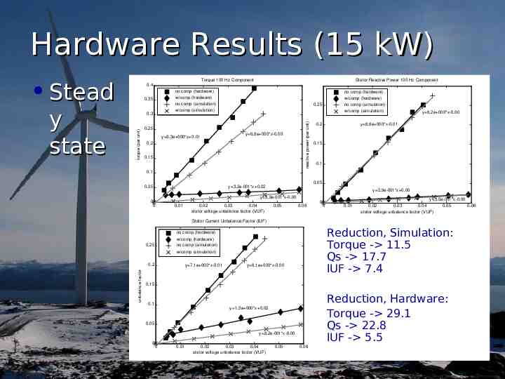
Hardware Results (15 kW) Stead Stator Reactive Power 100 Hz Component no comp (hardware) w/comp (hardware) no comp (simulation) w/comp (simulation) torque (per unit) 0.3 0.25 y 9.3e 000*x 0.01 no comp (hardware) w/comp (hardware) no comp (simulation) w/comp (simulation) 0.25 y 6.8e 000*x-0.00 0.2 0.15 reactive power (per unit) 0.35 0.2 y 6.2e 000*x-0.00 y 6.6e 000*x-0.01 0.15 0.1 0.1 0.05 0 0.05 y 3.2e-001*x 0.02 y 2.9e-001*x 0.00 y 5.9e-001*x-0.00 0 0.01 0.02 0.03 0.04 stator voltage unbalance factor (VUF) 0.05 0.06 0 0 0.01 y 3.5e-001*x-0.00 0.02 0.03 0.04 0.05 0.06 stator voltage unbalance factor (VUF) Stator Current Unbalance Factor (IUF) Reduction, Simulation: Torque - 11.5 Qs - 17.7 IUF - 7.4 no comp (hardware) w/comp (hardware) no comp (simulation) w/comp (simulation) 0.25 0.2 unbalance factor y state Torque 100 Hz Component 0.4 y 7.1e 000*x-0.01 y 6.1e 000*x-0.00 0.15 0.1 Reduction, Hardware: Torque - 29.1 Qs - 22.8 IUF - 5.5 y 1.3e 000*x 0.02 0.05 y 8.2e-001*x-0.00 0 0 0.01 0.02 0.03 0.04 stator voltage unbalance factor (VUF) 0.05 0.06
Thank You! Questions?