Switching Theory & Logic Design Laboratory Debdeep


30 Slides1.05 MB
Switching Theory & Logic Design Laboratory Debdeep Mukhopadhyay Associate Professor Dept of Computer Science and Engineering IIT Kharagpur 1
Chapter 0 2
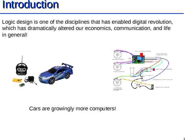
Introduction Logic design is one of the disciplines that has enabled digital revolution, which has dramatically altered our economics, communication, and life in general! Cars are growingly more computers! 3
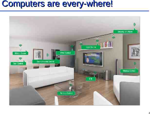
Computers are every-where! 4
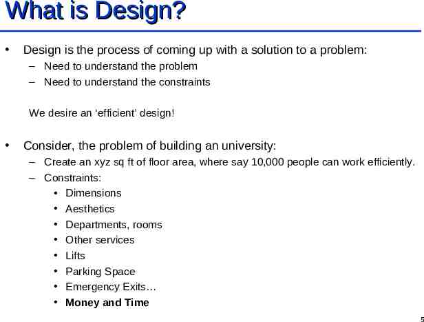
What is Design? Design is the process of coming up with a solution to a problem: – Need to understand the problem – Need to understand the constraints We desire an ‘efficient’ design! Consider, the problem of building an university: – Create an xyz sq ft of floor area, where say 10,000 people can work efficiently. – Constraints: Dimensions Aesthetics Departments, rooms Other services Lifts Parking Space Emergency Exits Money and Time 5
Divide and Conquer A very efficient methodology which humans have developed because of their inability of handling too many details! Divide the problem into sub-problems: – Associate sub-contractors (Split/Divide) Each have their own design problems Continues in a recursive fashion – Merge the solutions (Conquer) The chief-architect is responsible for integrating Toughest job! Good communication and team work is a key! – It is difficult for the stair-case contractor to ask to change the dimensions of the hall for better flight. – Or, to widen the elevator shaft after developing the building. 6
Top-down and Bottom-up Approaches Both strategies of information processing and knowledge ordering A top down approach breaks up a bigger picture into subsystems, which are often like black-boxes, initially. A Bottom-up approach starts with systems and connects them together to form bigger systems. Top down approach is about planning, and starts implementations after the complete picture is clear. – Delays testing Bottom up approach on the other hand stresses on implementation and testing from the beginning. – Problem may be integration/linking of modules. – Good for reuse of design. Real life design combines both. 7
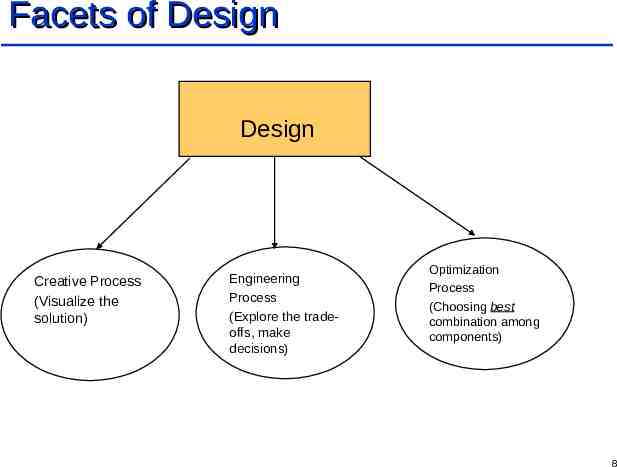
Facets of Design Design Creative Process (Visualize the solution) Engineering Process (Explore the tradeoffs, make decisions) Optimization Process (Choosing best combination among components) 8
Digital/Logic Design A digital designer uses components from digital electronics to solve problems in real life. Transistors from CMOS (Complementary MOS) forms the core. A digital designer abstracts it like a switch. Circuit: An inter-connected collection of switches 9
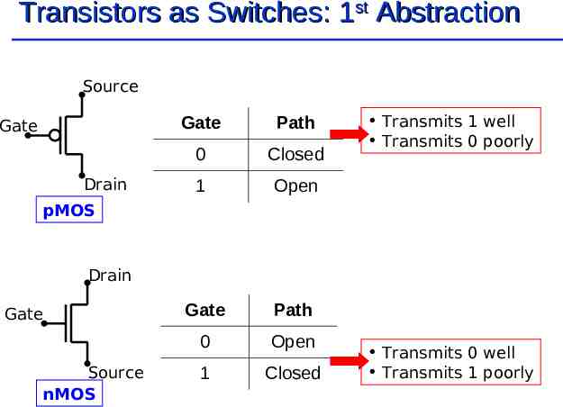
Transistors as Switches: 1st Abstraction Source Gate Drain Gate Path 0 Closed 1 Open Gate Path 0 Open 1 Closed Transmits 1 well Transmits 0 poorly pMOS Drain Gate Source nMOS Transmits 0 well Transmits 1 poorly
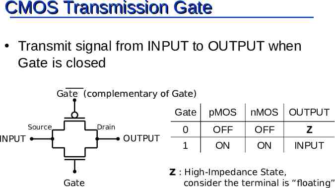
CMOS Transmission Gate Transmit signal from INPUT to OUTPUT when Gate is closed Gate (complementary of Gate) Gate Source Drain OUTPUT INPUT Gate Gate pMOS nMOS OUTPUT 0 OFF OFF Z 1 ON ON INPUT Z : High-Impedance State, consider the terminal is “floating”
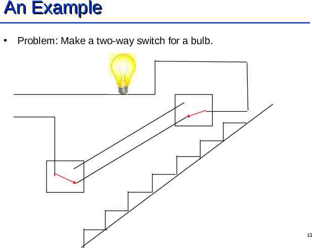
An Example Problem: Make a two-way switch for a bulb. 12
An Example Problem: Make a two-way switch for a bulb. 13
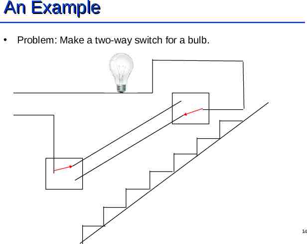
An Example Problem: Make a two-way switch for a bulb. 14
An Example Problem: Make a two-way switch for a bulb. 15
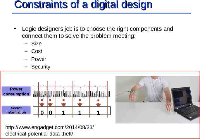
Constraints of a digital design Logic designers job is to choose the right components and connect them to solve the problem meeting: – – – – Size Cost Power Security Power consumption Secret information 0 0 1 1 http://www.engadget.com/2014/08/23/ electrical-potential-data-theft/ 1
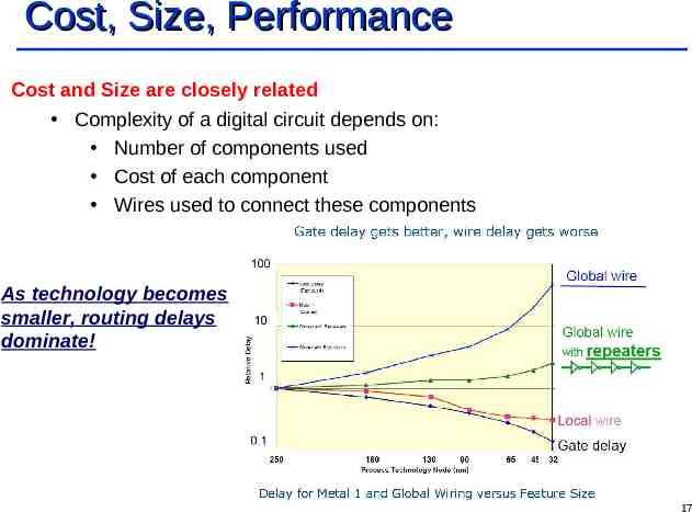
Cost, Size, Performance Cost and Size are closely related Complexity of a digital circuit depends on: Number of components used Cost of each component Wires used to connect these components As technology becomes smaller, routing delays dominate! 17
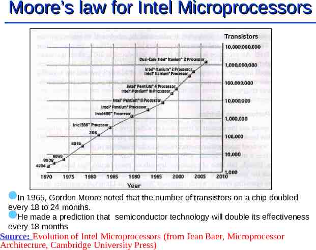
Moore’s law for Intel Microprocessors In 1965, Gordon Moore noted that the number of transistors on a chip doubled every 18 to 24 months. He made a prediction that semiconductor technology will double its effectiveness every 18 months Source: Evolution of Intel Microprocessors (from Jean Baer, Microprocessor Architecture, Cambridge University Press)
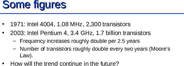
Some figures 1971: Intel 4004, 1.08 MHz, 2,300 transistors 2003: Intel Pentium 4, 3.4 GHz, 1.7 billion transistors – Frequency increases roughly double per 2.5 years – Number of transistors roughly double every two years (Moore’s Law). How will the trend continue in the future?
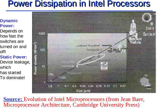
Power Dissipation in Intel Processors Dynamic Power: Depends on how fast the switches are turned on and off! Static Power: Device leakage, which has started To dominate! Source: Evolution of Intel Microprocessors (from Jean Baer, Microprocessor Architecture, Cambridge University Press)
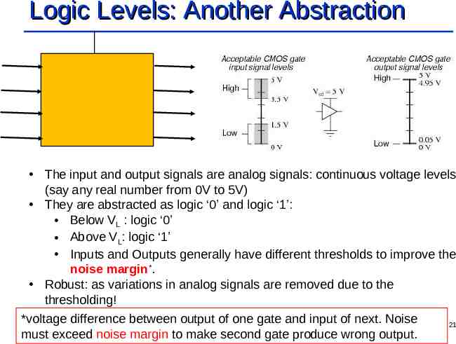
Logic Levels: Another Abstraction The input and output signals are analog signals: continuous voltage levels (say any real number from 0V to 5V) They are abstracted as logic ‘0’ and logic ‘1’: Below VL : logic ‘0’ Above VL: logic ‘1’ Inputs and Outputs generally have different thresholds to improve the noise margin*. Robust: as variations in analog signals are removed due to the thresholding! *voltage difference between output of one gate and input of next. Noise must exceed noise margin to make second gate produce wrong output. 21
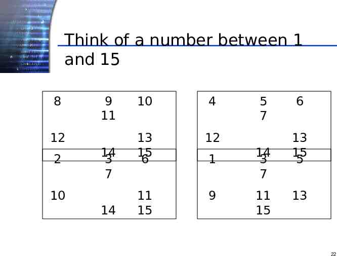
Think of a number between 1 and 15 8 9 11 12 2 14 3 7 10 14 10 4 13 15 6 12 11 15 9 1 5 7 14 3 7 11 15 6 13 15 5 13 22
Binary Numbers Yes 1 No 0 Number 7 appears on the four cards in the pattern ‘No, Yes, Yes, Yes’ The number 7 in binary code is 0111 This is the Digital Language! 23
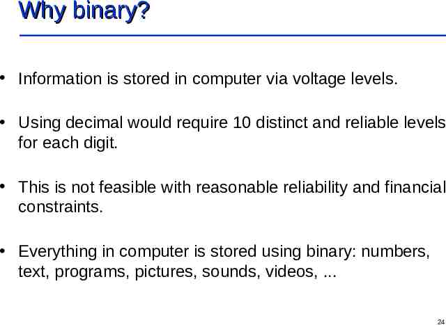
Why binary? Information is stored in computer via voltage levels. Using decimal would require 10 distinct and reliable levels for each digit. This is not feasible with reasonable reliability and financial constraints. Everything in computer is stored using binary: numbers, text, programs, pictures, sounds, videos, . 24
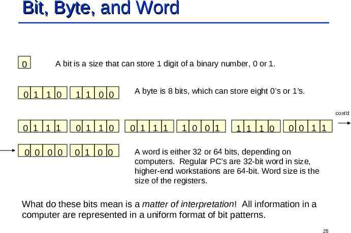
Bit, Byte, and Word 0 A bit is a size that can store 1 digit of a binary number, 0 or 1. 0 1 1 0 1 1 0 0 A byte is 8 bits, which can store eight 0’s or 1’s. cont’d 0 1 1 1 0 1 1 0 0 0 0 0 0 1 0 0 0 1 1 1 1 0 0 1 1 1 1 0 0 0 1 1 A word is either 32 or 64 bits, depending on computers. Regular PC’s are 32-bit word in size, higher-end workstations are 64-bit. Word size is the size of the registers. What do these bits mean is a matter of interpretation! All information in a computer are represented in a uniform format of bit patterns. 25
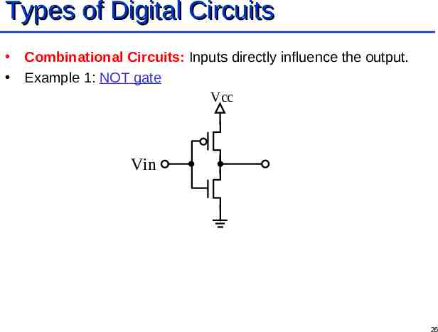
Types of Digital Circuits Combinational Circuits: Inputs directly influence the output. Example 1: NOT gate Vcc Vin 26
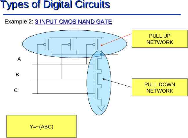
Types of Digital Circuits Example 2: 3 INPUT CMOS NAND GATE PULL UP NETWORK A B PULL DOWN NETWORK C Y (ABC)
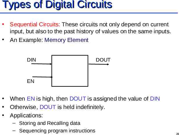
Types of Digital Circuits Sequential Circuits: These circuits not only depend on current input, but also to the past history of values on the same inputs. An Example: Memory Element DIN DOUT EN When EN is high, then DOUT is assigned the value of DIN Otherwise, DOUT is held indefinitely. Applications: – Storing and Recalling data – Sequencing program instructions 28
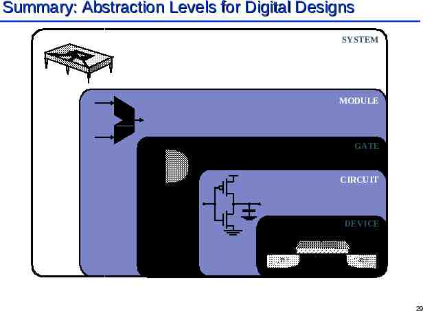
Summary: Abstraction Levels for Digital Designs SYSTEM MODULE GATE CIRCUIT DEVICE G S n D n 29
Summary: Logic Design Set of abstractions and methodologies that help us configure large number of digital circuits to solve a given problem. Need to learn methodologies for developing a systematic design flow to take a concept and transform into reality. We also need to learn optimization techniques, and meet constraints better! Necessity is the mother of invention! Constraints give rise to innovations, and make the job worthy! 30