SRv6 Clarence Filsfils Cisco Fellow – cf@cisco


75 Slides4.66 MB
SRv6 Clarence Filsfils Cisco Fellow - [email protected]
Segment Routing Source Routing – the topological and service (NFV) path is encoded in the packet header Scalability – the network fabric does not hold any per-flow state for TE or NFV Simplicity – automation: TILFA – protocol elimination: LDP, RSVP-TE, NSH End-to-End 2014 Cisco and/or its affiliates. All rights reserved. 2
Industry at large backs up SR Strong customer adoption WEB, SP, Enterprise Standardization IETF De-Facto SDN Architecture Multi-vendor Consensus Interop testings 2014 Cisco and/or its affiliates. All rights reserved. 3
Objective of SRv6
IPv6 provides reachability Micro-services IoT services IP 5G 4G Metro/Core Network Legacy DC Next-Gen Data Center xDSL FTTH 5G 5G Cable Source Address Support 5G growth IPv6 addresses summarization Destination Address Support container adoption for micro-services IPv6 2014 Cisco and/or its affiliates. All rights reserved. 5
SRv6 for underlay SRv6 RSVPfor forUnderlay FRR/TE Horrendous states in k*N 2 Simplification, FRR,scaling TE, SDN IPv6 for reach 2014 Cisco and/or its affiliates. All rights reserved. 6
Opportunity for further simplification NSH for NFV UDP VxLAN Overlay SRv6 for Underlay Additional Protocol and State Additional Protocol just for tenant ID Simplification, FRR, TE, SDN IPv6 for reach Multiplicity of protocols and states hinder network economics 2014 Cisco and/or its affiliates. All rights reserved. 7
Network Programming
Network instruction Locator Function(arg) Function 128-bit SRv6 SID – Locator: routed to the node performing the function – Function: any possible function (optional argument) either local to NPU or app in VM/Container – Flexible bit-length selection 2014 Cisco and/or its affiliates. All rights reserved. 9
Network Program in the packet header IPv6 Header Segment Routing Header IPv6 Payload Source Address Next Segment Destination Address Locator 1 Function 1 Locator 1 Function 1 Locator 2 Function 2 Locator 3 Function 3 TCP, UDP, QUIC 2014 Cisco and/or its affiliates. All rights reserved. 10
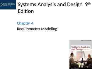
Network Program Next Segment Locator 1 Function 1 Locator 2 Function 2 Locator 3 Function 3 Locator 2 Locator 1 Function 1 Function 2 Locator 3 2014 Cisco and/or its affiliates. All rights reserved. Function 3 11
Network Program Next Segment Locator 1 Function 1 Locator 2 Function 2 Locator 3 Function 3 Locator2 Locator 1 Function 1 Function2 Locator 3 2014 Cisco and/or its affiliates. All rights reserved. Function 3 12
Network Program Next Segment Locator 1 Function 1 Locator 2 Function 2 Locator 3 Function 3 Locator 2 Locator 1 Function 1 Function 2 Locator 3 2014 Cisco and/or its affiliates. All rights reserved. Function 3 13
Argument shared between functions Locator1 Function1 Argument1 Locator2 Function2 Argument2 Locator3 Function3 Argument3 “Global” Argument Metadata TLV 2014 Cisco and/or its affiliates. All rights reserved. 14
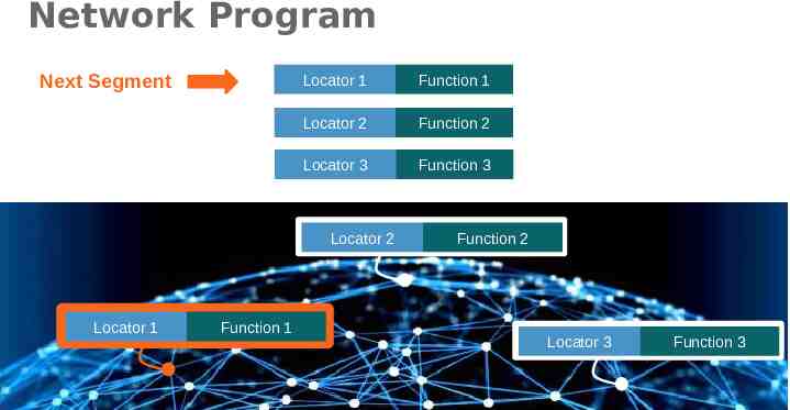
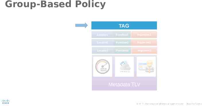
Group-Based Policy TAG Locator1 Function1 Argument1 Locator2 Function2 Argument2 Locator3 Function3 Argument3 Metadata TLV 2014 Cisco and/or its affiliates. All rights reserved. 15
SR Header TAG Segments Left Locator 1 Function 1 Locator 2 Function 2 Locator 3 Function 3 Metadata TLV 2014 Cisco and/or its affiliates. All rights reserved. 16
SRv6 for anything TAG Segments Left Locator 1 Function 1 Locator 2 Function 2 Locator 3 Function 3 Turing Metadata TLV 2014 Cisco and/or its affiliates. All rights reserved. 17
SRv6 for anything TAG Segments Left Locator 1 Function 1 Locator 2 Function 2 Locator 3 Function 3 Optimized for HW processing e.g. Underlay & Tenant use-cases Optimized for SW processing e.g. NFV, Container, Micro-Service Metadata TLV 2014 Cisco and/or its affiliates. All rights reserved. 18
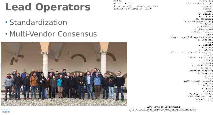
Lead Operators Standardization Multi-Vendor Consensus 2014 Cisco and/or its affiliates. All rights reserved. 19
2014 Cisco and/or its affiliates. All rights reserved. 20
SRv6 for Next-generation Mobile 2014 Cisco and/or its affiliates. All rights reserved. 21
Use-Cases
SID allocation for illustration purpose For simplicity Node K 12 10 advertises prefix AK::/64 The function is A1::/64 2 4 1 7 13 encoded in the last 64 bits 3 11 6 5 A5::/64 14 DC WAN 2014 Cisco and/or its affiliates. All rights reserved. PEER 23
Endpoint For simplicity Function 0 denotes the most basic function 12 10 A1::0 2 4 1 7 13 Shortest-path to 3 the Node 11 6 5 A5::0 14 DC WAN 2014 Cisco and/or its affiliates. All rights reserved. PEER 24
A1::0 and then A5::0 12 10 A1::0 2 4 1 7 13 3 11 6 5 A5::0 14 DC WAN 2014 Cisco and/or its affiliates. All rights reserved. PEER 25
Endpoint then xconnect to neighbor For simplicity AK::CJ denotes Shortest-path to the Node K and then x-connect (function C) to the neighbor J 12 10 A1::C2 2 4 1 7 13 3 6 5 A5::C7 11 14 DC WAN 2014 Cisco and/or its affiliates. All rights reserved. PEER 26
A1::0 and then A5::C7 12 10 A1::0 2 4 1 7 13 3 6 5 A5::C7 11 14 DC WAN 2014 Cisco and/or its affiliates. All rights reserved. PEER 27
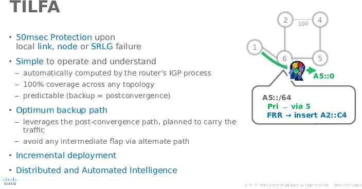
TILFA 2 100 4 50msec Protection upon local link, node or SRLG failure 1 6 Simple to operate and understand – automatically computed by the router’s IGP process 5 A5::0 – 100% coverage across any topology – predictable (backup postconvergence) Optimum backup path – leverages the post-convergence path, planned to carry the traffic A5::/64 Pri via 5 FRR insert A2::C4 – avoid any intermediate flap via alternate path Incremental deployment Distributed and Automated Intelligence 2014 Cisco and/or its affiliates. All rights reserved. 28
INSERT A2::C4 TILFA 2 100 4 A5::0 50msec Protection upon local link, node or SRLG failure 1 6 Simple to operate and understand A5::0 – automatically computed by the router’s IGP process 5 50mec FRR – 100% coverage across any topology – predictable (backup postconvergence) Optimum backup path – leverages the post-convergence path, planned to carry the traffic – avoid any intermediate flap via alternate path Incremental deployment Distributed and Automated Intelligence 2014 Cisco and/or its affiliates. All rights reserved. 29
Overlay IPv6 ( T::1, V::1 ) payload Simple – Protocol elimination Automated – No tunnel to configure Efficient – SRv6 for everything – Reuse BGP/VPN signaling T/64 3 1 Green Overlay V/64 via A2::C4 IPv6 ( A1::0, A2::C4 ) IPv6 ( T::1, V::1 ) payload 2 IPv6 ( T::1, V::1 ) payload 4 V/64 2014 Cisco and/or its affiliates. All rights reserved. 30
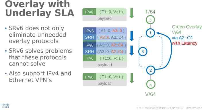
Overlay with Underlay SLA SRv6 does not only eliminate unneeded overlay protocols SRv6 solves problems that these protocols cannot solve Also support IPv4 and Ethernet VPN’s IPv6 T/64 ( T1::0, V::1 ) payload IPv6 3 ( A1::0, A3::0 ) 1 SRH { A3::0, A2::C4 } IPv6 ( A1::0, ( T1::0,A2::C4 V::1 ) ) IPv6 SRH {payload A3::0, A2::C4 } IPv6 Green Overlay V/64 via A2::C4 with Latency 3 ( T1::0, V::1 ) payload 2 IPv6 ( T1::0, V::1 ) payload 4 V/64 2014 Cisco and/or its affiliates. All rights reserved. 31
Integrated NFV T/64 IPv6 Stateless Service Chaining – NSH creates per-chain state in the fabric IPv6 – SR does not App is SR aware or not App can work on IPv6 or IPv4 inner packets ( T1::0, V2::0 ) payload 3 1 Server 3 ( A1::0, A3::A32 ) SRH { A3::A32, A4::0, A5::A76, A2::C4 } IPv6 ( T1::0, V2::0 ) 3 App 32 Container 4 Server 5 payload 5 App 76 VM 2 4 V/64 2014 Cisco and/or its affiliates. All rights reserved. 32
T/64 Integrated NFV 3 1 Integrated SLA IPv6 Server 3 ( A1::0, A4::0 ) SRH { A3::A32, A4::0, A5::A76, A2::C4 } IPv6 ( T1::0, V2::0 ) 3 App 32 Container 4 Server 5 payload 5 App 76 VM 2 4 V/64 2014 Cisco and/or its affiliates. All rights reserved. 33
T/64 Integrated NFV Stateless Service Chaining – NSH creates per-chain state in the fabric – SR does not App is SR aware or not App can work on IPv6 or IPv4 inner packets 3 1 IPv6 Server 3 ( A1::0, A5::A76 ) SRH { A3::A32, A4::0, A5::A76, A2::C4 } IPv6 ( T1::0, V2::0 ) 3 App 32 Container 4 Server 5 payload 5 App 76 VM 2 4 V/64 2014 Cisco and/or its affiliates. All rights reserved. 34
T/64 Integrated NFV 3 1 Integrated with Overlay Server 3 ( A1::0, A2::C4 ) IPv6 SRH { A3::A32, A4::0, A5::A76, A2::C4 } IPv6 ( T1::0, V2::0 ) 3 4 Server 5 payload IPv6 ( T1::0, V2::0 ) payload App 32 Container 5 App 76 VM 2 4 V/64 2014 Cisco and/or its affiliates. All rights reserved. 35
More use-cases 6CN: enhancing IP to search for Content 6LB: enhancing load-balancers – Better flow stickiness and load distribution Video Pipeline 5G Slicing 5G Ultra-Low Latency 2014 Cisco and/or its affiliates. All rights reserved. 36
Implementations Cisco HW – NCS5k - XR – ASR9k - XR – ASR1k – XE Open-Source – Linux 4.10 – FD.IO Barefoot HW 2014 Cisco and/or its affiliates. All rights reserved. 37
VPN (v4 and v6) & & TE NFV Cisco HW with XR and XE Barefoot HW with P4 blogs.cisco.com/sp/segment-routing-ipv6-interoperability-demo-is-already-there code 2014 Cisco and/or its affiliates. All rights reserved. FD.IO 38
Deployments Comcast – Efficient transport of video traffic Others 2014 Cisco and/or its affiliates. All rights reserved. 39
Conclusion
Segment Routing Strong industry support Fantastic deployment rate Bold architecture: network programming Numerous use-cases Feel free to join the lead-operator team! 2014 Cisco and/or its affiliates. All rights reserved. 41
Stay Up-To-Date amzn.com/B01I58LSUO segment-routing.net linkedin.com/groups/8266623 twitter.com/SegmentRouting facebook.com/SegmentRouting/ 2014 Cisco and/or its affiliates. All rights reserved. 42
Thank you
Appendix
Other use-cases
Spray Spray Policy 1: A2::0, A4::0, M1, DD:: CMTS4 4 Spray Policy 2: A3::0, A5::0, M1, DD:: Content Provider VPP1 B::1 Unicasted 2 3 Replicate traffic to every CMTS through TE-Engineered core path then to access mcast tree then to anycast TV Peering to Content Provider WIFI TV-1 DD:: GW2 C::2 WIFI TV-2 DD:: GW3 C::3 WIFI TV-3 DD:: GW4 C::4 WIFI TV-4 DD:: GW5 C::5 WIFI TV-5 DD:: CMTS5 5 SRv6 domain (Unicast) SRv6 node GW1 C::1 Multicast domain Non SRv6 node Anycast Subscribed to M1 channel Flexible, SLA-enabled and Efficient content injection without multicast core 2014 Cisco and/or its affiliates. All rights reserved. 46
SRH Processing
Source Node 1 A1:: Source node is SR-capable SR Header (SRH) is created with – Segment list in reversed order of the path 2 A2:: IPv6 Hdr SA A1::, DA A2:: SR Hdr ( A4::, A3::, A2:: ) SL 2 3 A3:: 4 A4:: Payload Segment List [ ] is the LAST segment – Segments Left is set to – First Segment is set to IPv6 Hdr Segment List [ ] is the FIRST segment Packet is send according to the IP DA – Normal IPv6 forwarding SR Hdr IP DA is set to the first segment Version Traffic Class Payload Length FlowLabel Label Flow Next 43 Hop Limit Source Address A1:: Destination Address A2:: Next Header Len 6 First 2 Flags Type 4 SL 2 TAG Segment List [ 0 ] A4:: Segment List [ 1 ] A3:: Segment List [ 2 ] A2:: Payload 2014 Cisco and/or its affiliates. All rights reserved. 48
Non-SR Transit Node 1 A1:: 2 A2:: IPv6 Hdr SA A1::, DA A2:: SR Hdr ( A4::, A3::, A2:: ) SL 2 3 A3:: 4 A4:: Payload Plain IPv6 forwarding Solely based on IPv6 DA No SRH inspection or update 2014 Cisco and/or its affiliates. All rights reserved. 49
SR Segment Endpoints SR Endpoints: SR-capable nodes A A1:: 2 A2:: whose address is in the IP DA IPv6 Hdr 3 A3:: 4 A4:: SA A1::, DA A3:: SR Hdr ( A4::, A3::, A2:: ) SL 1 Payload SR Endpoints inspect the SRH and do: Decrement Segments Left ( -1 ) Update DA with Segment List [ Segments Left ] IPv6 Hdr – IF Segments Left 0, THEN SR Hdr Forward according to the new IP DA Version Traffic Class Payload Length FlowLabel Label Flow Next 43 Hop Limit Source Address A1:: Destination Address A3:: Next Header Len 6 First 2 Flags Type 4 SL 1 TAG Segment List [ 0 ] A4:: Segment List [ 1 ] A3:: Segment List [ 2 ] A2:: Payload 2014 Cisco and/or its affiliates. All rights reserved. 50
SR Segment Endpoints SR Endpoints: SR-capable nodes 1 A1:: 2 A2:: whose address is in the IP DA 3 A3:: IPv6 Hdr 4 A4:: SA A1::, DA A4:: SR Hdr ( A4::, A3::, A2:: ) SL 0 Payload SR Endpoints inspect the SRH and do: Decrement Segments Left ( -1 ) Update DA with Segment List [ Segments Left ] IPv6 Hdr – IF Segments Left 0, THEN – ELSE (Segments Left 0)Standard IPv6 processing The final destination does not Remove the IP and SR header have to be SR-capable. Process the payload: Inner IP: Lookup DA and forward TCP / UDP: Send to socket SR Hdr Forward according to the new IP DA Version Traffic Class Payload Length FlowLabel Label Flow Next 43 Hop Limit Source Address A1:: Destination Address A4:: Next Header Len 6 First 2 Flags Type 4 SL 0 TAG Segment List [ 0 ] A4:: Segment List [ 1 ] A3:: Segment List [ 2 ] A2:: Payload 2014 Cisco and/or its affiliates. All rights reserved. 51
Some obvious SID functions
Segment format Locator Function 1111 : 2222 : 3333 : 4444 : 5555 : 6666 : 7777 : 8888 SRv6 SIDs are 128-bit addresses – Locator: most significant bits are used to route the segment to its parent node – Function: least significant bits identify the action to be performed on the parent node Argument [optional]: Last bits can be used as a local function argument Flexible bit-length allocation – Segment format is local knowledge on the parent node SIDs have to be specifically enabled as such on their parent node – A local address is not by default a local SID – A local SID does not have to be associated with an interface 2014 Cisco and/or its affiliates. All rights reserved. 53
END – Default endpoint Default endpoint behavior (node segment) – Decrement Segments Left, update DA – Forward according to new DA Node 2 advertises prefix A2::/64 (A2::/64 is the SID locator) – Packets are forwarded to node 2 along the default routes (shortest path) On 2, the default endpoint behavior is associated with ID 0 (0 is the function) The SID corresponding to the default endpoint behavior on node 2 is A2::0 IPv6 Hdr SA A1::, DA A2::0 SR Hdr ( ,A3::,A2::0, ) SL k Payload 2 A2:: /64 3 IPv6 Hdr SA A1::, DA A3:: SR Hdr ( , A3::, A2::0, ) SL k-1 Payload 2014 Cisco and/or its affiliates. All rights reserved. 54
END.X – Endpoint then Xconnect Endpoint xconnect behavior (adjacency segment) – Decrement Segments Left, update DA – Forward on the interface associated with the Xconnect segment Node 3 advertises prefix A3::/64 – Packets are forwarded to node 3 along the default routes (shortest path) On 3, the endpoint xconnect behavior for link 1 is associated with ID C1 The SID corresponding to endpoint xconnect-1 behavior on node 3 is SA A1::, DA A4:: IPv6 Hdr A3::C1 SR Hdr ( , A4::, A3::C1, ) SL k-1 Payload IPv6 Hdr SA A1::, DA A3::C1 ( ,A4::, A3::C1, ) SR Hdr SL k Payload 1 4 3 A3:: /64 2 2014 Cisco and/or its affiliates. All rights reserved. 55
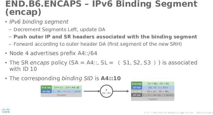
END.B6.ENCAPS – IPv6 Binding Segment (encap) IPv6 binding segment – Decrement Segments Left, update DA – Push outer IP and SR headers associated with the binding segment – Forward according to outer header DA (first segment of the new SRH) Node 4 advertises prefix A4::/64 The SR encaps policy (SA A4::, SL 〈 S1, S2, S3 〉 ) is associated with ID 10 The corresponding binding SID is A4::10 IPv6 Hdr IPv6 Hdr SA A1::, DA A4::10 SR Hdr ( , A5::, A4::10, ) SL k Payload 4 A4:: /64 SA A4::, DA S1 SR Hdr (S3, S2, S1) SL 2 IPv6 Hdr SA A1::, DA A5:: SR Hdr ( , A5::, A4::10, ) SL k-1 Payload 2014 Cisco and/or its affiliates. All rights reserved. 56
END.B6 – IPv6 Binding Segment (insert) IPv6 binding segment – Do not decrement Segments Left – Push outer SR header associated with the binding segment – Update DA with the first segment of the outer SR header – Forward according to outer header DA (first segment of the new SRH) Node 4 advertises prefix A4::/64 On 4, the SR insert policy 〈 S1, S2, S3 〉 is associated with ID 20 The corresponding binding SID is A4::20 IPv6 Hdr SA A1::, DA A4::20 SR Hdr ( ,A5::, A4::20, ) SL k Payload IPv6 Hdr SA A1::, DA S1 4 SR Hdr ( S3, S2, S1 ) SL 2 A4:: /64 SR Hdr ( ,A5::, A4::20, ) SL k Payload 2014 Cisco and/or its affiliates. All rights reserved. 57
END.BM – MPLS Binding Segment MPLS binding segment – Decrement Segments Left – Push outer MPLS label stack associated with the binding segment – Forward according to the top MPLS label Node 4 advertises prefix A4::/64 On 4, the MPLS SR policy L1, L2, L3 is associated with ID 30 The corresponding binding SID is A4::30 IPv6 Hdr SA A1::, DA A4::30 SR Hdr ( ,A5::, A4::30, ) SL k Payload 4 A4:: /64 MPLS { L1, L2, L3 } IPv6 Hdr SA A1::, DA A5:: SR Hdr ( ,A5::, A4::30, ) SL k-1 Payload 2014 Cisco and/or its affiliates. All rights reserved. 58
END.PSP – Penultimate Segment Popping Penultimate Segment Popping (PSP) behavior – Decrement Segments Left, update DA – If Segments Left 0, remove SRH – Forward according to new DA Node 5 advertises prefix A5::/64 On 5, the Penultimate Segment Popping behavior is associated with ID 1 The corresponding SID is A5::1 IPv6 Hdr SA A1::, DA A5::1 SR Hdr ( A6::, A5::1, ) SL 1 5 SR Hdr ( , A7::, ) SL k A5:: /64 Payload IPv6 Hdr SA A1::, DA A6:: SR Hdr ( , A7::, ) SL k Payload 2014 Cisco and/or its affiliates. All rights reserved. 60
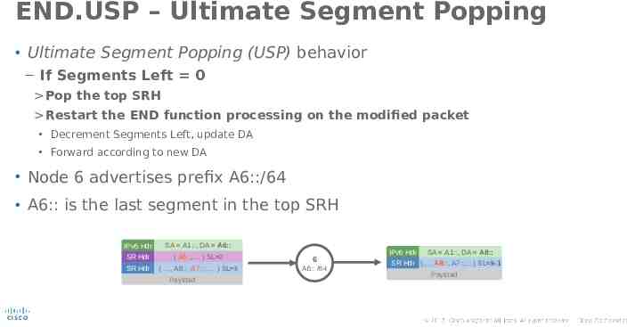
END.USP – Ultimate Segment Popping Ultimate Segment Popping (USP) behavior – If Segments Left 0 Pop the top SRH Restart the END function processing on the modified packet Decrement Segments Left, update DA Forward according to new DA Node 6 advertises prefix A6::/64 A6:: is the last segment in the top SRH IPv6 Hdr SA A1::, DA A6:: SR Hdr ( A6::, ) SL 0 6 SR Hdr ( , A8::, A7::, ) SL k A6:: /64 Payload IPv6 Hdr SA A1::, DA A8:: SR Hdr ( , A8::, A7::, ) SL k-1 Payload 2014 Cisco and/or its affiliates. All rights reserved. 61
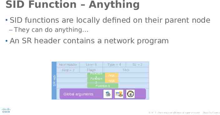
SID Function – Anything SID functions are locally defined on their parent node – They can do anything SR Hdr An SR header contains a network program Next Header Len 6 First 2 Flags Type 4 Function Segment ListArgs [0] 3 Function Segment ListArgs [1] 2 Function Segment List1 [ 2 ] Global arguments SL 2 TAG TLVs 2014 Cisco and/or its affiliates. All rights reserved. 62
IPv6 Segment Routing L3VPN and VNF chanining
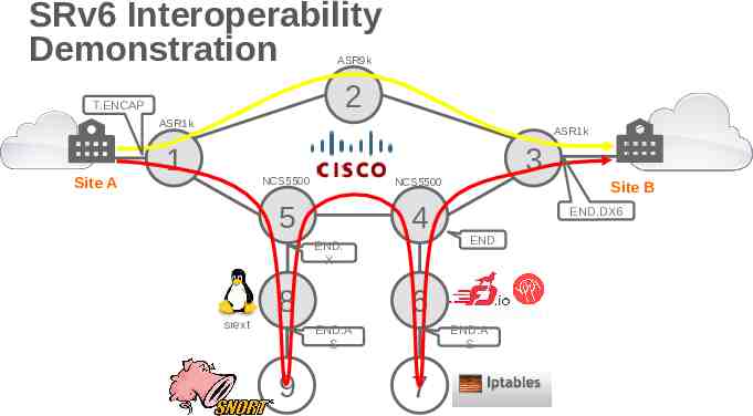
SRv6 Interoperability Demonstration ASR9k 2 T.ENCAP ASR1k Site A ASR1k 1 NCS5500 NCS5500 5 4 END. X srext 8 Site B END.DX6 END 6 END.A S 9 3 END.A S 7
L3 VPN with SRv6 BGP installs Prefix into RIB Prefix: 6001::/64 VPN SID: 2001:0:0:3:1:: iBGP-VPNv6 BGP Signaling VPN SID Session: BGP VPNv6 Prefix: 6001::/64 NH: 2001:0:0:3::1 VPN SID: 2001:0:0:3:1:: Locator 2 Lo0 2001:0:0:1::1 Site A END.DX6- 2001:0:0:3:1:: VRF:Enterprise100 1 3 Site B SA:2001:0:0:1::1 DA:2001:0:0:3:1:: NH:IPv6 SA:2001:0:0:1::1 DA:2001:0:0:3:1:: NH:IPv6 SA:4001::1 DA:6001::1 NH:UDP SA:4001::1 DA:6001::1 NH:UDP SA:4001::1 DA:6001::1 NH:UDP SA:4001::1 DA:6001::1 NH:UDP UDP Header/Data UDP Header/Data UDP Header/Data UDP Header/Data Best Effort Traffic Function
SRv6 VNF Chaining Site A SA:2001:0:0:1::1 DA:2001:0:0:5:58:: NH:IPv6 Type:4(SRH) NH:IPv6 SL:4 Segment List: [0]:2001:0:0:3:1:: [1]:2001:0:0:6:a:: [2]:2001:0:0:4:: [3]:2001:0:0:8:a:: [4]:2001:0:0:5:58:: SA:4001::1 DA:7001::1 NH:UDP UDP Header/Data 1 3 Site B 5 END.DX6 2001:0:0:3:1:: 4 END.X 2001:0:0:5:58:: END 2001:0:0:4:: 8 END.AS 2001:0:0:8:a:: 6 snort 9 END.AS 2001:0:0:6:a:: iptables 7
VNF Chaining ASR1k Site A SA:2001:0:0:1::1 DA:2001:0:0:8:a:: NH:IPv6 Type:4(SRH) NH:IPv6 SL:3 Segment List: [0]:2001:0:0:3:1:: [1]:2001:0:0:6:a:: [2]:2001:0:0:4:: [3]:2001:0:0:8:a:: [4]:2001:0:0:5:58:: SA:4001::1 DA:7001::1 NH:UDP UDP Header/Data 1 ASR1k NCS5500 NCS5500 5 END.X 2001:0:0:5:58:: 8 END.AS 2001:0:0:8:a:: Site B END.DX6 2001:0:0:3:1:: 4 Linux srext snort 9 3 END 2001:0:0:4:: VPP 6 END.AS 2001:0:0:6:a:: iptables 7
VNF Chaining ASR1k Site A 1 ASR1k NCS5500 NCS5500 5 END.X 2001:0:0:5:58:: 8 END.AS 2001:0:0:8:a:: SA:4001::1 DA:7001::1 NH:UDP UDP Header/Data Site B END.DX6 2001:0:0:3:1:: 4 Linux srext snort 9 3 END 2001:0:0:4:: VPP 6 END.AS 2001:0:0:6:a:: iptables 7
VNF Chaining ASR1k Site A SA:2001:0:0:1::1 DA:2001:0:0:4:: NH:IPv6 Type:4(SRH) NH:IPv6 SL:2 Segment List: [0]:2001:0:0:3:1:: [1]:2001:0:0:6:a:: [2]:2001:0:0:4:: [3]:2001:0:0:8:a:: [4]:2001:0:0:5:58:: SA:4001::1 DA:7001::1 NH:UDP UDP Header/Data 1 ASR1k NCS5500 NCS5500 5 END.X 2001:0:0:5:58:: 8 END.AS 2001:0:0:8:a:: Site B END.DX6 2001:0:0:3:1:: 4 Linux srext snort 9 3 END 2001:0:0:4:: VPP 6 END.AS 2001:0:0:6:a:: iptables 7
VNF Chaining ASR1k Site A 1 ASR1k NCS5500 NCS5500 5 END.X 2001:0:0:5:58:: 8 END.AS 2001:0:0:8:a:: Site B END.DX6 2001:0:0:3:1:: 4 Linux srext snort 9 3 END 2001:0:0:4:: VPP Type:4(SRH) NH:IPv6 SL:1 Segment List: 6 END.AS 2001:0:0:6:a:: iptables 7 SA:2001:0:0:1::1 DA:2001:0:0:6:a:: NH:IPv6 [0]:2001:0:0:3:1:: [1]:2001:0:0:6:a:: [2]:2001:0:0:4:: [3]:2001:0:0:8:a:: [4]:2001:0:0:5:58:: SA:4001::1 DA:7001::1 NH:UDP UDP Header/Data
VNF Chaining ASR1k Site A 1 ASR1k NCS5500 NCS5500 5 END.X 2001:0:0:5:58:: 8 END.AS 2001:0:0:8:a:: Site B END.DX6 2001:0:0:3:1:: 4 Linux srext snort 9 3 END 2001:0:0:4:: VPP 6 END.AS 2001:0:0:6:a:: iptables 7 SA:4001::1 DA:7001::1 NH:UDP UDP Header/Data
VNF Chaining ASR1k Site A 1 ASR1k NCS5500 NCS5500 5 END.X 2001:0:0:5:58:: 8 END.AS 2001:0:0:8:a:: Site B END.DX6 2001:0:0:3:1:: 4 Linux srext snort 9 3 END 2001:0:0:4:: VPP Type:4(SRH) NH:IPv6 SL:0 Segment List: 6 END.AS 2001:0:0:6:a:: iptables 7 SA:2001:0:0:1::1 DA:2001:0:0:3:1:: NH:IPv6 [0]:2001:0:0:3:1:: [1]:2001:0:0:6:a:: [2]:2001:0:0:4:: [3]:2001:0:0:8:a:: [4]:2001:0:0:5:58:: SA:4001::1 DA:7001::1 NH:UDP UDP Header/Data
VNF Chaining ASR1k Site A 1 ASR1k NCS5500 NCS5500 5 END.X 2001:0:0:5:58:: 8 END.AS 2001:0:0:8:a:: Site B END.DX6 2001:0:0:3:1:: 4 Linux srext snort 9 3 END 2001:0:0:4:: VPP 6 SA:4001::1 DA:7001::1 NH:UDP END.AS 2001:0:0:6:a:: iptables 7 UDP Header/Data
We Demonstrated L3VPN and VNF chaining SRv6 Hardware based forwarding ASR 1000, Cisco ASR 9000, Cisco NCS 5500, Cisco SRv6 Software based forwarding VPP fd.io Linux srext 2014 Cisco and/or its affiliates. All rights reserved. 74
Stay Up-To-Date http://www.segment-routing.net/ https://www.linkedin.com/groups/8266623 https://twitter.com/SegmentRouting https://www.facebook.com/SegmentRouting/ Segment Routing, Part I - Textbook
Thank you