“Insulators 101” Section A – Introduction Presented by Andy Schwalm


84 Slides4.86 MB
“Insulators 101” Section A – Introduction Presented by Andy Schwalm IEEE Chairman, Lightning and Insulator Subcommittee IEEE/PES 2010 Transmission and Distribution Conference and Exposition New Orleans, Louisiana April 20, 2010 IEEE T&D – Insulators 101
What Is an Insulator? An insulator is a “dam***” poor conductor! And more, technically speaking! An insulator is a mechanical support! Primary function - support the “line” mechanically Secondary function– electrical Air is the insulator Outer shells/surfaces are designed to increase leakage distance and strike distance IEEE T&D – Insulators 101
What Does an Insulator Do? Maintains an Air Gap Separates Line from Ground length of air gap depends primarily on system voltage, modified by desired safety margin, contamination, etc. Resists Mechanical Stresses “everyday” loads, extreme loads Resists Electrical Stresses system voltage/fields, overvoltages Resists Environmental Stresses heat, cold, UV, contamination, etc. IEEE T&D – Insulators 101
Where Did Insulators Come From? Basically grew out of the needs of the telegraph industry – starting in the late 1700s, early 1800s Early history centers around what today we would consider very low DC voltages Gradually technical needs increased as AC voltages grew with the development of the electric power industry IEEE T&D – Insulators 101
History Glass plates used to insulate telegraph line DC to Baltimore Glass insulators became the ”norm” soon thereafter – typical collector’s items today Many, many trials with different materials – wood – cement – porcelain - beeswax soaked rag wrapped around the wire, etc. Ultimately porcelain and glass prevailed IEEE T&D – Insulators 101
History Wet process porcelain developed for high voltage applications Porcelain insulator industry started Application voltages increased Insulator designs became larger, more complex Ceramics (porcelain, glass) still only choices at high voltages IEEE T&D – Insulators 101
History US trials of first “NCIs” – cycloaliphatic based Not successful, but others soon became interested and a new industry started up Europeans develop “modern” style NCI – fiberglass rod with various polymeric sheds Now considered “First generation” IEEE T&D – Insulators 101
History NCI insulator industry really begins in US with field trials of insulators Since that time - new manufacturers, new designs, new materials NCIs at “generation X” – there have been so many improvements in materials, end fitting designs, etc. Change in materials have meant changes in line design practices, maintenance practices, etc. Ceramic manufacturers have not been idle either with development of higher strength porcelains, RG glazes, etc. IEEE T&D – Insulators 101
History Domestic manufacturing of insulators decreases, shift to offshore (all types) Engineers need to develop knowledge and skills necessary to evaluate and compare suppliers and products from many different countries An understanding of the basics of insulator manufacturing, design and application is more essential than ever before IEEE T&D – Insulators 101
Insulator Types For simplicity will discuss in terms of three broad applications: Distribution lines (thru 69 kV) Transmission lines (69 kV and up) Substations (all voltages) IEEE T&D – Insulators 101
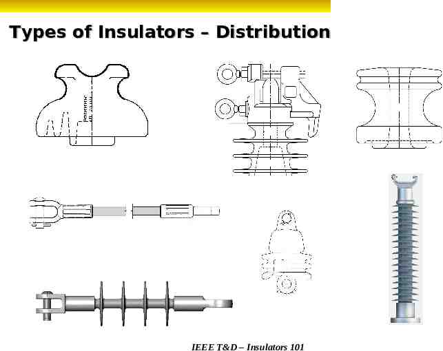
Insulator Types Distribution lines Pin type insulators -mainly porcelain, growing use of polymeric (HDPE – high density polyethylene), limited use of glass (in US at least) Line post insulators – porcelain, polymeric Dead end insulators – polymeric, porcelain, glass Spool insulators – porcelain, polymeric Strain insulators, polymeric, porcelain IEEE T&D – Insulators 101
Types of Insulators – Distribution IEEE T&D – Insulators 101
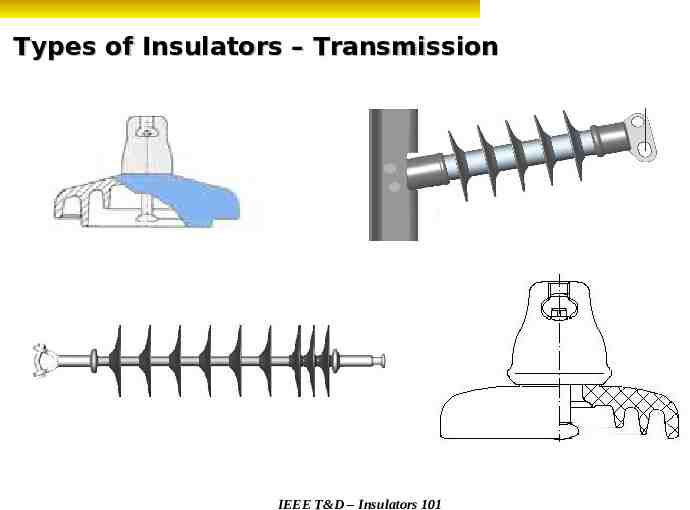
Insulator Types Transmission lines Suspension insulators - new installations mainly NCIs, porcelain and glass now used less frequently Line post insulators – mainly NCIs for new lines and installations, porcelain much less frequent now IEEE T&D – Insulators 101
Types of Insulators – Transmission IEEE T&D – Insulators 101
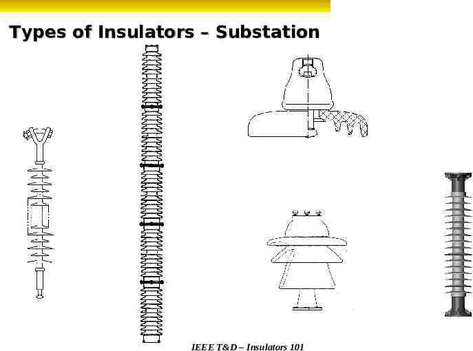
Insulator Types Substations Post insulators – porcelain primarily, NCIs growing in use at lower voltages ( 161 kV and below) Suspension insulators –NCIs (primarily), ceramic Cap and Pin insulators – “legacy” type IEEE T&D – Insulators 101
Types of Insulators – Substation IEEE T&D – Insulators 101
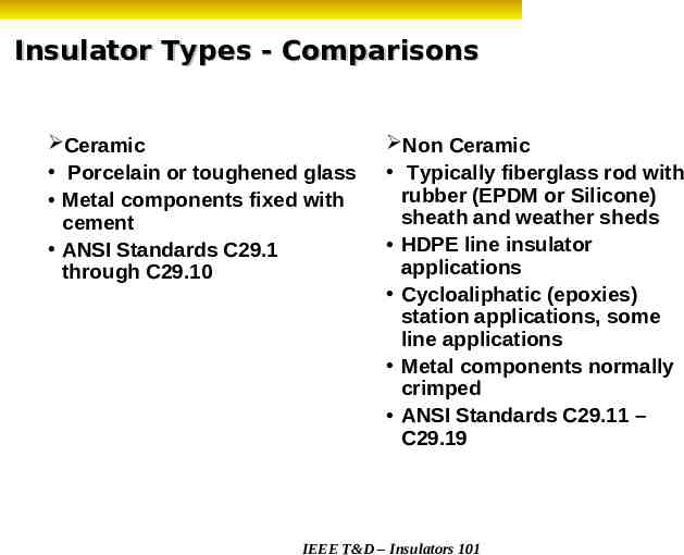
Insulator Types - Comparisons Ceramic Porcelain or toughened glass Metal components fixed with cement ANSI Standards C29.1 through C29.10 Non Ceramic Typically fiberglass rod with rubber (EPDM or Silicone) sheath and weather sheds HDPE line insulator applications Cycloaliphatic (epoxies) station applications, some line applications Metal components normally crimped ANSI Standards C29.11 – C29.19 IEEE T&D – Insulators 101
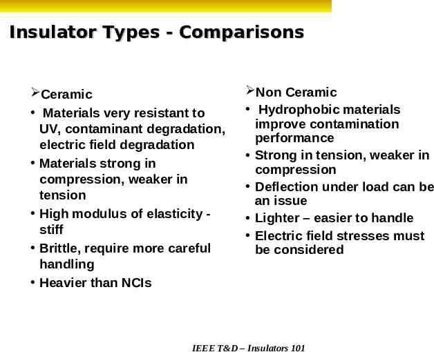
Insulator Types - Comparisons Ceramic Materials very resistant to UV, contaminant degradation, electric field degradation Materials strong in compression, weaker in tension High modulus of elasticity stiff Brittle, require more careful handling Heavier than NCIs Non Ceramic Hydrophobic materials improve contamination performance Strong in tension, weaker in compression Deflection under load can be an issue Lighter – easier to handle Electric field stresses must be considered IEEE T&D – Insulators 101
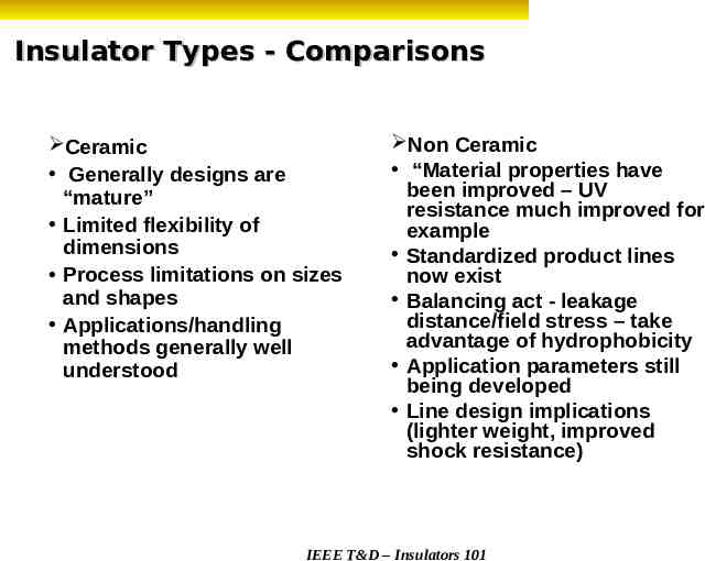
Insulator Types - Comparisons Ceramic Generally designs are “mature” Limited flexibility of dimensions Process limitations on sizes and shapes Applications/handling methods generally well understood Non Ceramic “Material properties have been improved – UV resistance much improved for example Standardized product lines now exist Balancing act - leakage distance/field stress – take advantage of hydrophobicity Application parameters still being developed Line design implications (lighter weight, improved shock resistance) IEEE T&D – Insulators 101
“Insulators 101” Section B - Design Criteria Presented by Al Bernstorf IEEE Chairman, Insulator Working Group IEEE/PES 2010 Transmission and Distribution Conference and Exposition New Orleans, Louisiana April 20, 2010 IEEE T&D – Insulators 101
Design Criteria - Mechanical An insulator is a mechanical support! Its primary function is to support the line mechanically Electrical Characteristics are an afterthought. Will the insulator support your line? Determine The Maximum Load the Insulator Will Ever See Including NESC Overload Factors. IEEE T&D – Insulators 101
Design Criteria - Mechanical Suspension Insulators Porcelain - M&E (Mechanical & Electrical) Rating Represents a mechanical test of the unit while energized. When the porcelain begins to crack, it electrically punctures. Average ultimate strength will exceed the M&E Rating when new. - Never Exceed 50% of the M&E Rating NCIs (Polymer Insulators) - S.M.L. – Specified Mechanical Load Guaranteed minimum ultimate strength when new. R.T.L. – Routine Test Load – Proof test applied to each NCI. - Never Load beyond the R.T.L. IEEE T&D – Insulators 101
Design Criteria - Mechanical Line Post insulators Porcelain - Cantilever Rating Represents the Average Ultimate Strength in Cantilever – when new. Minimum Ultimate Cantilever of a single unit may be as low as 85%. - Never Exceed 40% of the Cantilever Rating – Proof Test Load NCIs (Polymer Insulators) - S.C.L. (Specified Cantilever Load) Not based upon lot testing Based upon manufacturer testing - R.C.L. (Rated Cantilever Load) or MDC or MDCL (Maximum Design Cantilever Load) or MCWL or WCL (Working Cantilever Load) - Never Exceed RCL or MDC or MDCL or MCWL or WCL - S.T.L. (Specified Tensile Load) - Tensile Proof Test (STL/2) IEEE T&D – Insulators 101
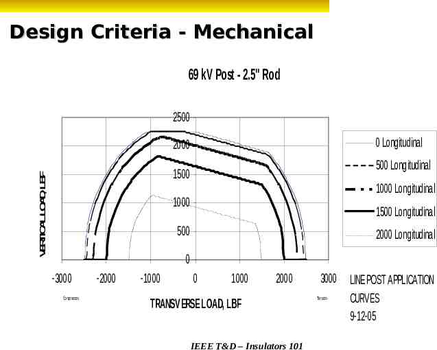
Design Criteria - Mechanical Other Considerations Suspensions and Deadends – Only apply tension loads Line Posts – - Cantilever is only one load - Transverse (tension or compression) on line post – loading transverse to the direction of the line. - Longitudinal – in the direction of travel of the line - Combined Loading Curve – Contour curves representing various Longitudinal loads Available Vertical load as a function of Transverse loading Manufacturers have different safety factors!!! IEEE T&D – Insulators 101
Design Criteria - Mechanical 69 kV Post - 2.5" Rod 2500 0 Longitudinal 2000 500 Longitudinal V E R TIC A LLO A D , LB F 1500 1000 Longitudinal 1000 1500 Longitudinal 500 2000 Longitudinal 0 -3000 Compression -2000 -1000 0 1000 2000 TRANSVERSE LOAD, LBF IEEE T&D – Insulators 101 3000 LINE POST APPLICATION CURVES 9-12-05 Tension
Design Criteria - Electrical An Insulator is a mechanical support! Air imparts Electrical Characteristics Strike Distance (Dry Arcing Distance) is the principal constituent to electrical values. Dry 60 Hz F/O and Impulse F/O – based on strike distance. Wet 60 Hz F/O - Some would argue leakage distance as a principal factor. - At the extremes that argument fails – although it does play a role. - Leakage distance helps to maintain the surface resistance of the strike distance. Leakage Requirements do play a role!!! IEEE T&D – Insulators 101
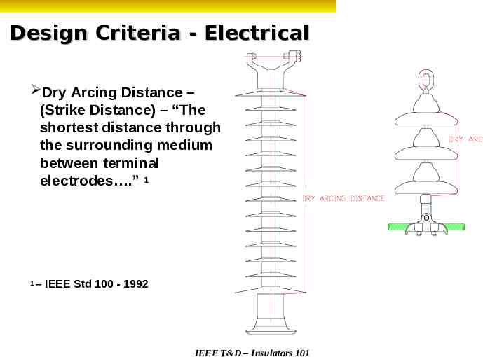
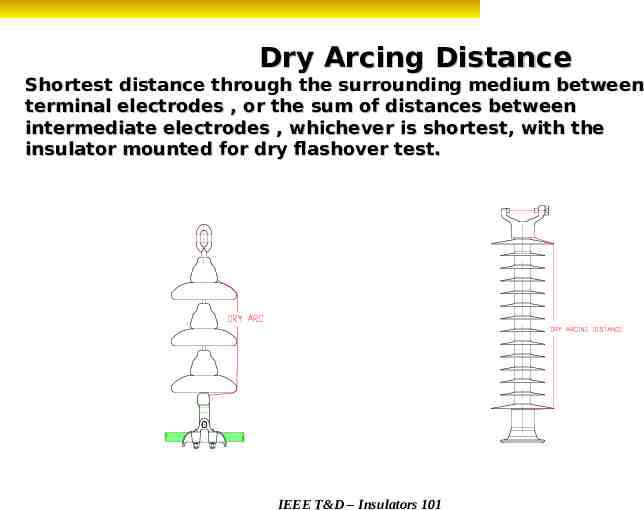
Design Criteria - Electrical Dry Arcing Distance – (Strike Distance) – “The shortest distance through the surrounding medium between terminal electrodes .” 1 1 – IEEE Std 100 - 1992 IEEE T&D – Insulators 101
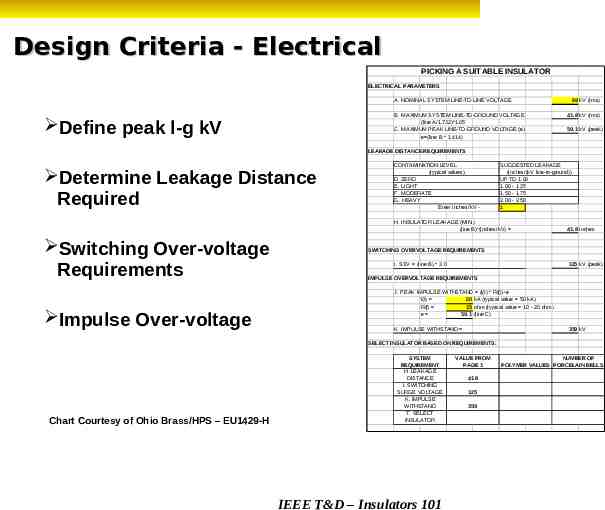
Design Criteria - Electrical PICKING A SUITABLE INSULATOR ELECTRICAL PARAMETERS A. NOMINAL SYSTEM LINE-TO-LINE VOLTAGE B. MAXIMUM SYSTEM LINE-TO-GROUND VOLTAGE (line A/1.732)*1.05 C. MAXIMUM PEAK LINE-TO-GROUND VOLTAGE (e) e (line B * 1.414) Define peak l-g kV 69 kV (rms) 41.8 kV (rms) 59.1 kV (peak) LEAKAGE DISTANCE REQUIREMENTS Determine Leakage Distance Required CONTAMINATION LEVEL (typical values) D. ZERO E. LIGHT F. MODERATE G. HEAVY Enter inches/kV - SUGGESTED LEAKAGE (inches/(kV line-to-ground)) UP TO 1.00 1.00 - 1.25 1.50 - 1.75 2.00 - 2.50 1 H. INSULATOR LEAKAGE (MIN.) (line B)*(inches/kV) Switching Over-voltage Requirements Impulse Over-voltage 41.8 inches SWITCHING OVERVOLTAGE REQUIREMENTS I. SSV (line B) * 3.0 125 kV (peak) IMPULSE OVERVOLTAGE REQUIREMENTS J. PEAK IMPULSE WITHSTAND (I(t) * R(f)) e I(t) 20 kA (typical value 50 kA) R(f) 15 ohm (typical value 10 - 20 ohm) e 59.1 (line C) K. IMPULSE WITHSTAND 359 kV SELECT INSULATOR BASED ON REQUIREMENTS: Chart Courtesy of Ohio Brass/HPS – EU1429-H SYSTEM REQUIREMENT H. LEAKAGE DISTANCE I. SWITCHING SURGE VOLTAGE K. IMPULSE WITHSTAND T. SELECT INSULATOR IEEE T&D – Insulators 101 VALUE FROM PAGE 1 41.8 125 359 NUMBER OF POLYMER VALUES PORCELAIN BELLS
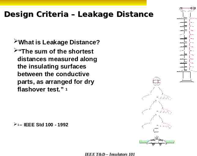
Design Criteria – Leakage Distance What is Leakage Distance? “The sum of the shortest distances measured along the insulating surfaces between the conductive parts, as arranged for dry flashover test.” 1 1 – IEEE Std 100 - 1992 IEEE T&D – Insulators 101
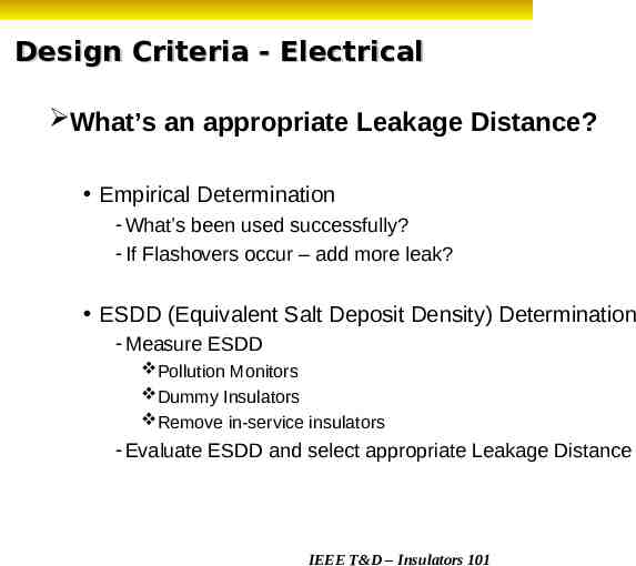
Design Criteria - Electrical What’s an appropriate Leakage Distance? Empirical Determination - What’s been used successfully? - If Flashovers occur – add more leak? ESDD (Equivalent Salt Deposit Density) Determination - Measure ESDD Pollution Monitors Dummy Insulators Remove in-service insulators - Evaluate ESDD and select appropriate Leakage Distance IEEE T&D – Insulators 101
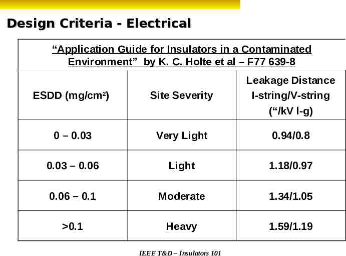
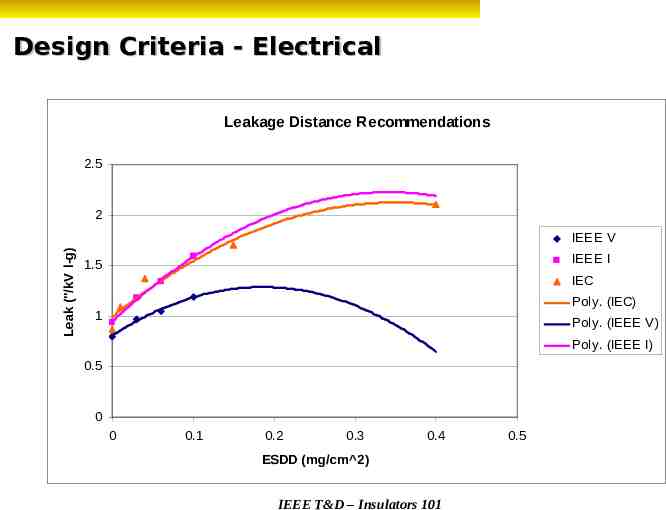
Design Criteria - Electrical “Application Guide for Insulators in a Contaminated Environment” by K. C. Holte et al – F77 639-8 ESDD (mg/cm2) Site Severity Leakage Distance I-string/V-string (“/kV l-g) 0 – 0.03 Very Light 0.94/0.8 0.03 – 0.06 Light 1.18/0.97 0.06 – 0.1 Moderate 1.34/1.05 0.1 Heavy 1.59/1.19 IEEE T&D – Insulators 101
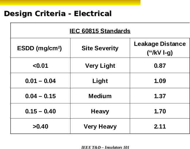
Design Criteria - Electrical IEC 60815 Standards ESDD (mg/cm ) Site Severity Leakage Distance (“/kV l-g) 0.01 Very Light 0.87 0.01 – 0.04 Light 1.09 0.04 – 0.15 Medium 1.37 0.15 – 0.40 Heavy 1.70 0.40 Very Heavy 2.11 2 IEEE T&D – Insulators 101
Design Criteria - Electrical Leakage Distance Recommendations 2.5 2 Leak ("/kV l-g) IEEE V IEEE I 1.5 IEC Poly. (IEC) 1 Poly. (IEEE V) Poly. (IEEE I) 0.5 0 0 0.1 0.2 0.3 0.4 ESDD (mg/cm 2) IEEE T&D – Insulators 101 0.5
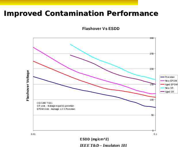
Improved Contamination Performance Flashover Vs ESDD 300 250 Flashover Voltage 200 Porcelain New EPDM 150 Aged EPDM New SR Aged SR 100 CEA 280 T 621 SR units - leakage equal to porcelain EPDM Units - leakage 1.3 X Porcelain 50 0 0.01 0.1 ESDD (mg/cm 2) IEEE T&D – Insulators 101
Improved Contamination Performance Polymer insulators offer better contamination flashover performance than porcelain? Smaller core and weathershed diameter increase leakage current density. Higher leakage current density means more Ohmic Heating. Ohmic Heating helps to dry the contaminant layer and reduce leakage currents. In addition, hydrophobicity helps to minimize filming IEEE T&D – Insulators 101
Improved Contamination Performance “the contamination performance of composite insulators exceeds that of their porcelain counterparts” “the contamination flashover performance of silicone insulators exceeds that of EPDM units” “the V50 of polymer insulators increases in proportion to the leakage distance” CEA 280 T 621, “Leakage Distance Requirements for Composite Insulators Designed for Transmission Lines” IEEE T&D – Insulators 101
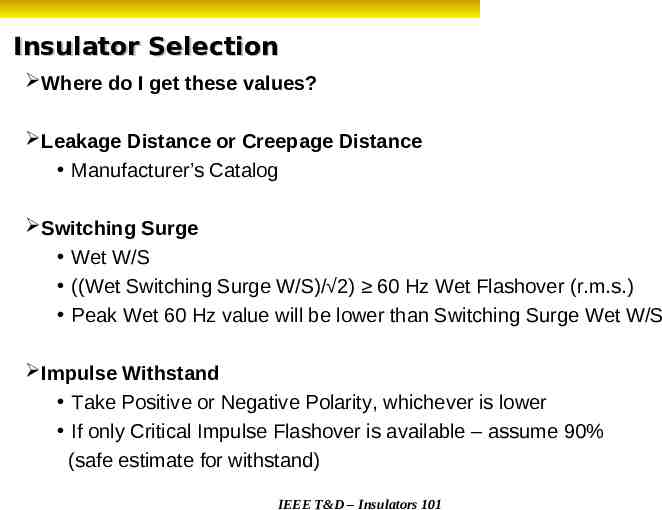
Insulator Selection Where do I get these values? Leakage Distance or Creepage Distance Manufacturer’s Catalog Switching Surge Wet W/S ((Wet Switching Surge W/S)/ 2) 60 Hz Wet Flashover (r.m.s.) Peak Wet 60 Hz value will be lower than Switching Surge Wet W/S Impulse Withstand Take Positive or Negative Polarity, whichever is lower If only Critical Impulse Flashover is available – assume 90% (safe estimate for withstand) IEEE T&D – Insulators 101
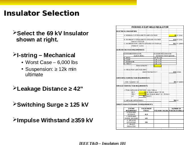
Insulator Selection PICKING A SUITABLE INSULATOR Select the 69 kV Insulator shown at right. ELECTRICAL PARAMETERS A. NOMINAL SYSTEM LINE-TO-LINE VOLTAGE B. MAXIMUM SYSTEM LINE-TO-GROUND VOLTAGE (line A/1.732)*1.05 C. MAXIMUM PEAK LINE-TO-GROUND VOLTAGE (e) e (line B * 1.414) 69 kV (rms) 41.8 kV (rms) 59.1 kV (peak) LEAKAGE DISTANCE REQUIREMENTS I-string – Mechanical CONTAMINATION LEVEL (typical values) D. ZERO E. LIGHT F. MODERATE G. HEAVY Enter inches/kV - Worst Case – 6,000 lbs Suspension: 12k min ultimate SUGGESTED LEAKAGE (inches/(kV line-to-ground)) UP TO 1.00 1.00 - 1.25 1.50 - 1.75 2.00 - 2.50 1 H. INSULATOR LEAKAGE (MIN.) (line B)*(inches/kV) 41.8 inches SWITCHING OVERVOLTAGE REQUIREMENTS I. SSV (line B) * 3.0 Leakage Distance 42” Switching Surge 125 kV Impulse Withstand 359 kV 125 kV (peak) IMPULSE OVERVOLTAGE REQUIREMENTS J. PEAK IMPULSE WITHSTAND (I(t) * R(f)) e I(t) 20 kA (typical value 50 kA) R(f) 15 ohm (typical value 10 - 20 ohm) e 59.1 (line C) K. IMPULSE WITHSTAND 359 kV SELECT INSULATOR BASED ON REQUIREMENTS: SYSTEM REQUIREMENT H. LEAKAGE DISTANCE I. SWITCHING SURGE VOLTAGE K. IMPULSE WITHSTAND T. SELECT INSULATOR IEEE T&D – Insulators 101 VALUE FROM PAGE 1 41.8 125 359 NUMBER OF POLYMER VALUES PORCELAIN BELLS
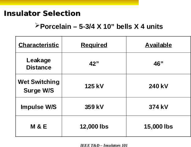
Insulator Selection Porcelain – 5-3/4 X 10” bells X 4 units Characteristic Required Available Leakage Distance 42” 46” Wet Switching Surge W/S 125 kV 240 kV Impulse W/S 359 kV 374 kV M&E 12,000 lbs 15,000 lbs IEEE T&D – Insulators 101
Grading Rings Simulate a larger, more spherical object Reduce the gradients associated with the shielded object Reduction in gradients helps to minimize RIV & TVI Porcelain or Glass – Inorganic – breaks down very slowly NCIs Polymers are more susceptible to scissioning due to corona UV – short wavelength range – attacks polymer bonds. Most short wavelength UV is filtered by the environment UV due to corona is not filtered IEEE T&D – Insulators 101
NCIs and Rings Grading (Corona) Rings Due to “corona cutting” and water droplet corona – NCIs may require the application of rings to grade the field on the polymer material of the weathershed housing. Rings must be: - Properly positioned relative to the end fitting on which they are mounted. - Oriented to provide grading to the polymer material. Consult the manufacturer for appropriate instructions. As a general rule – rings should be over the polymer – brackets should be on the hardware. IEEE T&D – Insulators 101
Questions? IEEE T&D – Insulators 101
Insulators 101 Section C - Standards Presented by Tony Baker IEEE Task Force Chairman, Insulator Loading IEEE/PES 2010 Transmission and Distribution Conference and Exposition New Orleans, Louisiana April 20, 2010 IEEE T&D – Insulators 101
American National Standards Consensus standards Standards writing bodies must include representatives from materially affected and interested parties. Public review Anybody may comment. Comments must be evaluated, responded to, and if found to be appropriate, included in the standard . Right to appeal By anyone believing due process lacking. Objective is to ensure that ANS Standards are developed in an environment that is equitable, accessible, and responsive to the requirements of various stakeholders*. * The American National Standards Process, ANSI March 24, 2005 IEEE T&D – Insulators 101
American Standards Committee on Insulators for Electric Power Lines ASC C-29 EL&P Group IEEE NEMA Independents IEEE T&D – Insulators 101
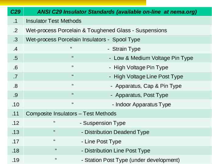
C29 ANSI C29 Insulator Standards (available on-line at nema.org) .1 Insulator Test Methods .2 Wet-process Porcelain & Toughened Glass - Suspensions .3 Wet-process Porcelain Insulators - Spool Type .4 “ - Strain Type .5 “ - Low & Medium Voltage Pin Type .6 “ - High Voltage Pin Type .7 “ - High Voltage Line Post Type .8 “ - Apparatus, Cap & Pin Type .9 “ - Apparatus, Post Type .10 “ - Indoor Apparatus Type .11 Composite Insulators – Test Methods .12 “ - Suspension Type .13 “ - Distribution Deadend Type .17 “ - Line Post Type .18 “ - IEEE Distribution Line Post Type T&D – Insulators 101 .19 “ - Station Post Type (under development)
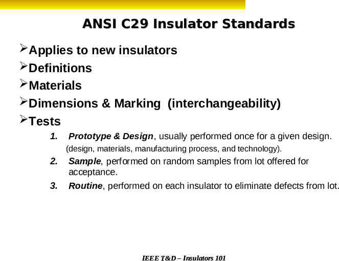
ANSI C29 Insulator Standards Applies to new insulators Definitions Materials Dimensions & Marking (interchangeability) Tests 1. Prototype & Design, usually performed once for a given design. (design, materials, manufacturing process, and technology). 2. 3. Sample, performed on random samples from lot offered for acceptance. Routine, performed on each insulator to eliminate defects from lot. IEEE T&D – Insulators 101
ANSI C 29 Insulator Standard Ratings Electrical & Mechanical Ratings How are they assigned? How is conformance demonstrated? What are application limits? IEEE T&D – Insulators 101
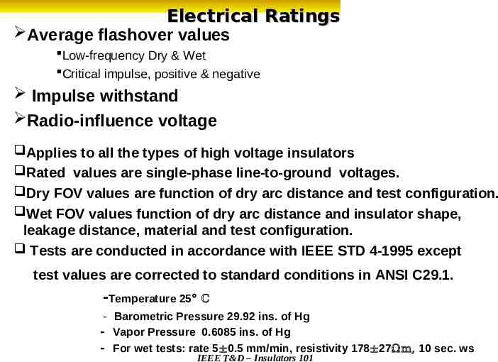
Electrical Ratings Average flashover values Low-frequency Dry & Wet Critical impulse, positive & negative Impulse withstand Radio-influence voltage Applies to all the types of high voltage insulators Rated values are single-phase line-to-ground voltages. Dry FOV values are function of dry arc distance and test configuration. Wet FOV values function of dry arc distance and insulator shape, leakage distance, material and test configuration. Tests are conducted in accordance with IEEE STD 4-1995 except test values are corrected to standard conditions in ANSI C29.1. -Temperature 25 C - Barometric Pressure 29.92 ins. of Hg - Vapor Pressure 0.6085 ins. of Hg - For wet tests: rate 5 0.5 mm/min, resistivity 178 27Ωm, 10 sec. ws IEEE T&D – Insulators 101
Dry Arcing Distance Shortest distance through the surrounding medium between terminal electrodes , or the sum of distances between intermediate electrodes , whichever is shortest, with the insulator mounted for dry flashover test. IEEE T&D – Insulators 101
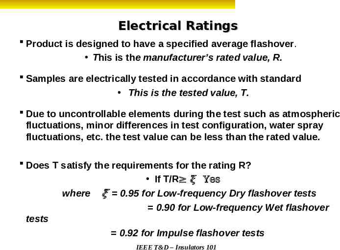
Electrical Ratings Product is designed to have a specified average flashover. This is the manufacturer’s rated value, R. Samples are electrically tested in accordance with standard This is the tested value, T. Due to uncontrollable elements during the test such as atmospheric fluctuations, minor differences in test configuration, water spray fluctuations, etc. the test value can be less than the rated value. Does T satisfy the requirements for the rating R? where If T/R 𝝃 Yes 𝝃 0.95 for Low-frequency Dry flashover tests 0.90 for Low-frequency Wet flashover tests 0.92 for Impulse flashover tests IEEE T&D – Insulators 101
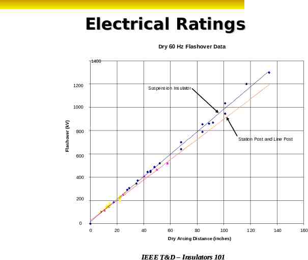
Electrical Ratings Dry 60 Hz Flashover Data 1400 1200 Suspension Insulator Flashover (kV) 1000 800 Station Post and Line Post 600 400 200 0 0 20 40 60 80 100 Dry Arcing Distance (inches) IEEE T&D – Insulators 101 120 140 160
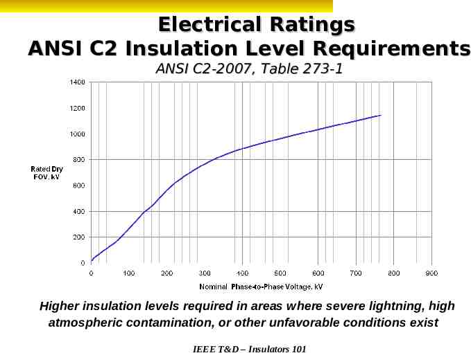
Electrical Ratings ANSI C2 Insulation Level Requirements ANSI C2-2007, Table 273-1 Higher insulation levels required in areas where severe lightning, high atmospheric contamination, or other unfavorable conditions exist IEEE T&D – Insulators 101
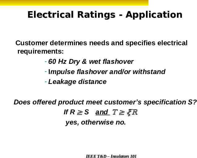
Electrical Ratings - Application Customer determines needs and specifies electrical requirements: - 60 Hz Dry & wet flashover - Impulse flashover and/or withstand - Leakage distance Does offered product meet customer’s specification S? If R S and T 𝝃R yes, otherwise no. IEEE T&D – Insulators 101
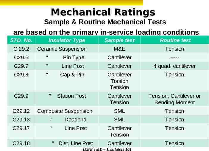
Mechanical Ratings Sample & Routine Mechanical Tests are based on the primary in-service loading conditions STD. No. C 29.2 Insulator Type Ceramic Suspension Sample test Routine test M&E Tension C29.6 “ Pin Type Cantilever ----- C29.7 “ Line Post Cantilever 4 quad. cantilever C29.8 “ Cap & Pin Cantilever Torsion Tension Tension Station Post Cantilever Tension Tension, Cantilever or Bending Moment SML Tension C29.9 C29.12 “ Composite Suspension C29.13 “ Deadend SML Tension C29.17 “ Line Post Cantilever Tension Tension C29.18 “ Dist. Line Post Cantilever Tension IEEE T&D – Insulators 101
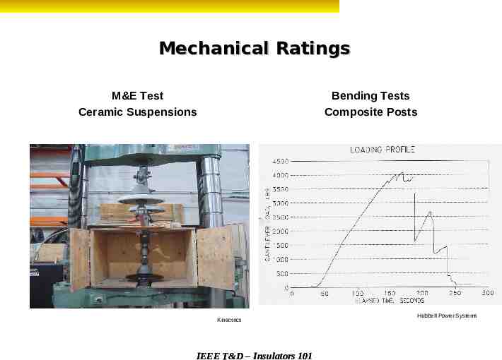
Mechanical Ratings Bending Tests Composite Posts M&E Test Ceramic Suspensions Kinectrics IEEE T&D – Insulators 101 Hubbell Power Systems
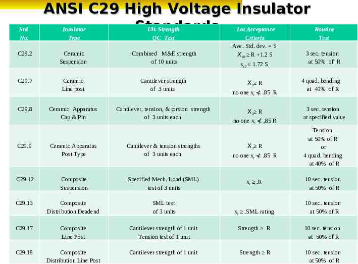
Std. No. C29.2 C29.7 C29.8 C29.9 ANSI C29 High Voltage Insulator Standards Insulator Ult. Strength Lot Acceptance Routine Type QC Test Ceramic Suspension Combined M&E strength of 10 units Ceramic Line post Cantilever strength of 3 units Ceramic Apparatus Cap & Pin Cantilever, tension, & torsion strength of 3 units each Criteria Ave. Std. dev. S X10 R 1.2 S s10 1.72 S X3 R no one xi .85 R X3 R no one xi .85 R X3 R Test 3 sec. tension at 50% of R 4 quad. bending at 40% of R 3 sec. tension at specified value Tension at 50% of R or 4 quad. bending at 40% of R Ceramic Apparatus Post Type Cantilever & tension strengths of 3 units each C29.12 Composite Suspension Specified Mech. Load (SML) test of 3 units C29.13 Composite Distribution Deadend SML test of 3 units C29.17 Composite Line Post Cantilever strength of 1 unit Tension test of 1 unit Strength R 10 sec. tension at 50% of R C29.18 Composite Distribution Line Post Cantilever 1 unit IEEEstrength T&D –ofInsulators 101 Strength R 10 sec. tension at 50% of R no one xi .85 R xi .R xi .SML rating 10 sec. tension at 50% of R 10 sec. tension at 50% of R
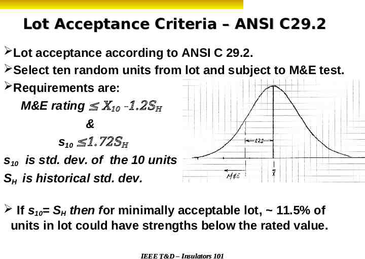
Lot Acceptance Criteria – ANSI C29.2 Lot acceptance according to ANSI C 29.2. Select ten random units from lot and subject to M&E test. Requirements are: M&E rating X10 -1.2SH & s10 1.72SH s10 is std. dev. of the 10 units SH is historical std. dev. If s10 SH then for minimally acceptable lot, 11.5% of units in lot could have strengths below the rated value. IEEE T&D – Insulators 101
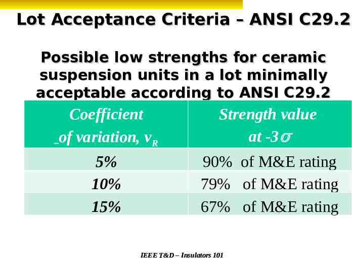
Lot Acceptance Criteria – ANSI C29.2 Possible low strengths for ceramic suspension units in a lot minimally acceptable according to ANSI C29.2 Coefficient of variation, vR Strength value at -3σ 5% 10% 15% 90% of M&E rating 79% of M&E rating 67% of M&E rating IEEE T&D – Insulators 101
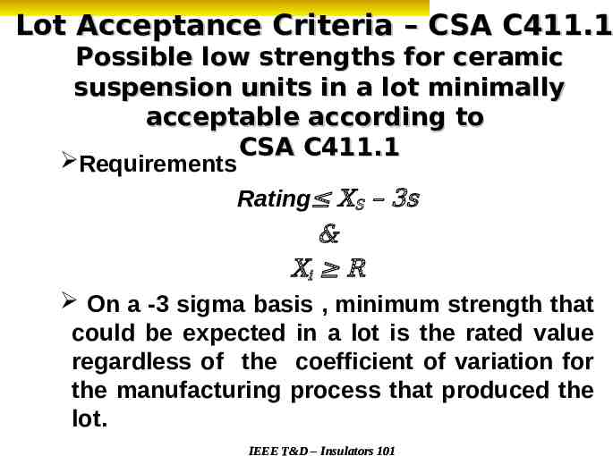
Lot Acceptance Criteria – CSA C411.1 Possible low strengths for ceramic suspension units in a lot minimally acceptable according to CSA C411.1 Requirements Rating XS – 3s & Xi R On a -3 sigma basis , minimum strength that could be expected in a lot is the rated value regardless of the coefficient of variation for the manufacturing process that produced the lot. IEEE T&D – Insulators 101
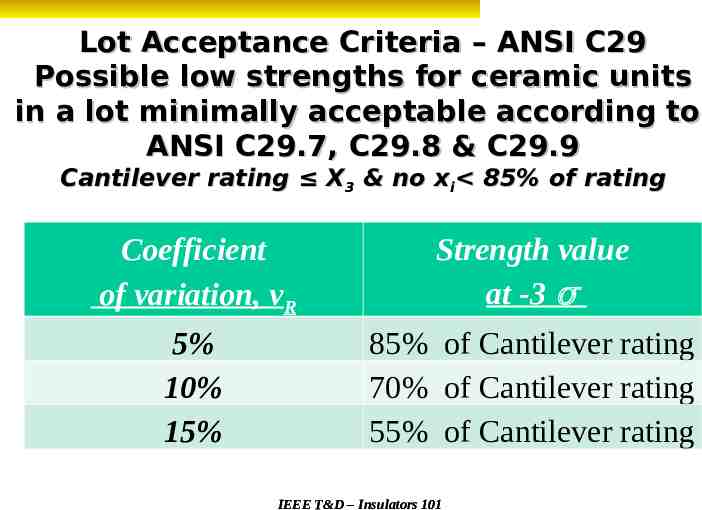
Lot Acceptance Criteria – ANSI C29 Possible low strengths for ceramic units in a lot minimally acceptable according to ANSI C29.7, C29.8 & C29.9 Cantilever rating X3 & no xi 85% of rating Coefficient of variation, vR Strength value at -3 σ 5% 10% 15% 85% of Cantilever rating 70% of Cantilever rating 55% of Cantilever rating IEEE T&D – Insulators 101
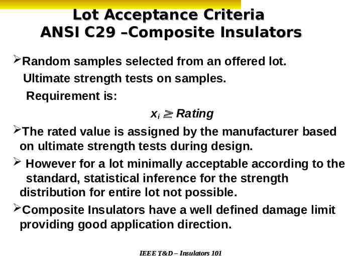
Lot Acceptance Criteria ANSI C29 –Composite Insulators Random samples selected from an offered lot. Ultimate strength tests on samples. Requirement is: xi Rating The rated value is assigned by the manufacturer based on ultimate strength tests during design. However for a lot minimally acceptable according to the standard, statistical inference for the strength distribution for entire lot not possible. Composite Insulators have a well defined damage limit providing good application direction. IEEE T&D – Insulators 101
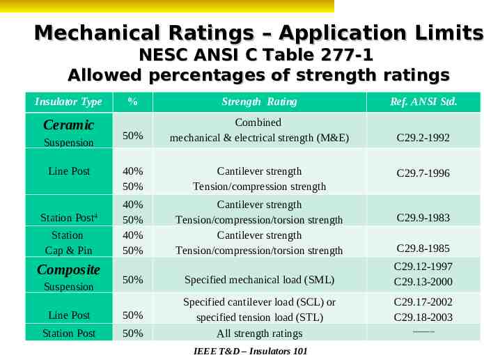
Mechanical Ratings – Application Limits NESC ANSI C Table 277-1 Allowed percentages of strength ratings Insulator Type Ceramic Suspension Line Post Station Post4 Station Cap & Pin Composite % Strength Rating Ref. ANSI Std. 50% Combined mechanical & electrical strength (M&E) C29.2-1992 40% 50% Cantilever strength Tension/compression strength 40% 50% 40% 50% Cantilever strength Tension/compression/torsion strength Cantilever strength Tension/compression/torsion strength 50% Specified mechanical load (SML) Line Post 50% Station Post 50% Specified cantilever load (SCL) or specified tension load (STL) All strength ratings Suspension IEEE T&D – Insulators 101 C29.7-1996 C29.9-1983 C29.8-1985 C29.12-1997 C29.13-2000 C29.17-2002 C29.18-2003 ----------
Mechanical Ratings – Application Limits Worst loading case load (% Table 277-1)(Insulator Rating) In most cases , % from Table 277-1 is equal to the routine proof -test load. Bending tests on a production basis are not practicable in some cases, (large stacking posts, cap & pins , and polymer posts) and tension proof-load tests are specified. IEEE T&D – Insulators 101
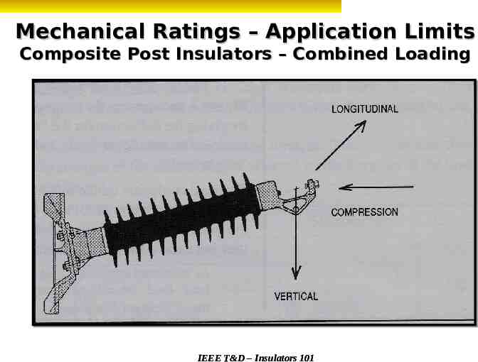
Mechanical Ratings – Application Limits Composite Post Insulators – Combined Loading IEEE T&D – Insulators 101
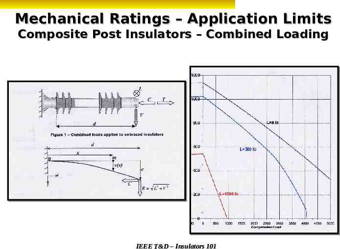
Mechanical Ratings – Application Limits Composite Post Insulators – Combined Loading IEEE T&D – Insulators 101
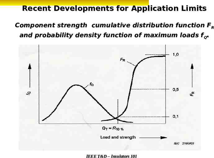
Recent Developments for Application Limits Component strength cumulative distribution function FR and probability density function of maximum loads fQ. IEEE T&D – Insulators 101
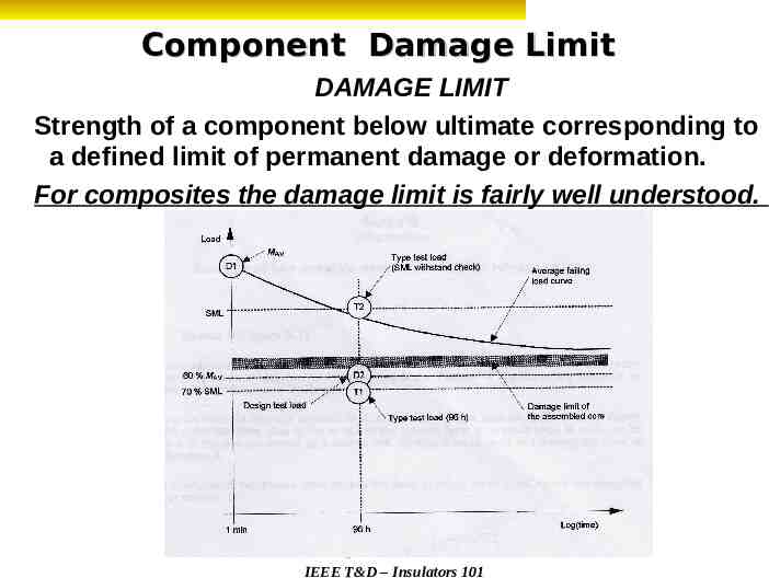
Component Damage Limit DAMAGE LIMIT Strength of a component below ultimate corresponding to a defined limit of permanent damage or deformation. For composites the damage limit is fairly well understood. IEEE T&D – Insulators 101 IEEE T&D – Insulators 101
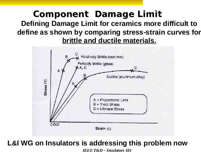
Component Damage Limit Defining Damage Limit for ceramics more difficult to define as shown by comparing stress-strain curves for brittle and ductile materials. L&I WG on Insulators is addressing this problem now IEEE T&D – Insulators 101
“Insulators 101” Section D – Achieving ‘Quality’ Presented by Tom Grisham IEEE Task Force Chairman, “Insulators 101” IEEE/PES – T&D Conference and Exposition New Orleans, LA IEEE T&D20, – Insulators 101 April 2010
Objectives of ‘Quality” Presentation Present ideas to verify the supplier qualification, purchasing requirements, manufacturer inspections of lots, shipment approval, material handling, and training information for personnel Routine inspection of the installation Identify steps to analyze field complaints To stimulate “Quality” improvement IEEE T&D – Insulators 101
‘Quality’ Defined QUALITY – An inherent, basic or distinguishing characteristic; an essential property or nature. QUALITY CONTROL – A system of ensuring the proper maintenance of written standards; especially by the random inspection of manufactured goods. IEEE T&D – Insulators 101
What Is Needed in a Quality Plan? Identifying critical design parameters Qualifying ‘new’ suppliers Evaluating current suppliers Establishing internal specifications Monitoring standards compliance (audits) Understanding installation requirements Establishing end-of-life criteria Ensuring safety of line workers Communicating and training All aspects defined by the company plan IEEE T&D – Insulators 101
What Documents Should Be Included? Catalog specifications and changes Supplier audit records and lot certification Qualification testing of the design Utility-specific testing Additional supplier testing for insulators (vibration, temperature, long-term performance, etc) ANSI or equivalent design reports Storage methods Installation records (where, by whom, why?) Interchangeability with other suppliers product Handling methods (consult manufacturer) Installation requirements and techniques IEEE T&D – Insulators 101
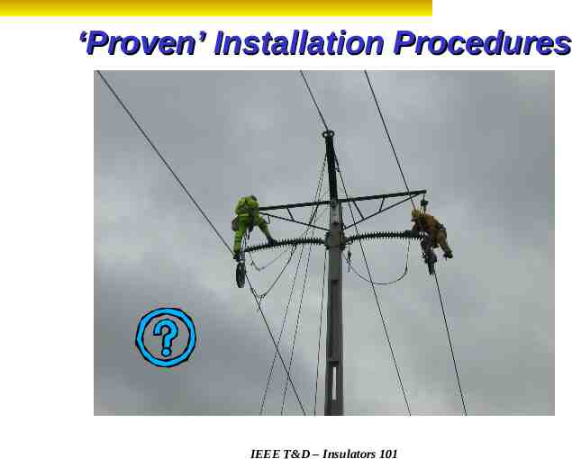
‘Proven’ Installation Procedures IEEE T&D – Insulators 101
Handling of Ceramics – NEMA HV21984 Insulators should not be dropped or thrown . Insulators strings should not be bent . Insulator strings are not ladders . Insulators with chips or cracks should be discarded and companion units should be carefully inspected . Cotter keys should be individually inspected for twisting, flattening or indentations. If found, replace keys and retest the insulator . The maximum combined load, including safety requirements of NESC, must not exceed the rating . Normal operating temperature range for ceramics is defined as –40 to 150 Degrees F . IEEE T&D – Insulators 101
Handling of NCI’s NEMA is working on a ‘new’ application guide for NCI products. It will likely include “Insulators should not be dropped, thrown, or bent ” “Insulators should not be used as ladders ” “Cotter keys for ball sockets should be inspected identically to the instructions for ceramic insulators ” “The maximum combined loads should not exceed the RTL ” Normal operating temperature is –40 to 150 Degrees F ” “Insulators should not be used as rope supports ” “Units with damaged housings that expose the core rod should be replaced and discarded ” “Units with cut or torn weathersheds should be inspected by the manufacturer ” “Bending, twisting and cantilever loading should be avoided during construction and maintenance ” IEEE T&D – Insulators 101
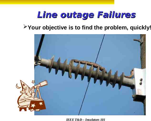
Line outage Failures Your objective is to find the problem, quickly! IEEE T&D – Insulators 101
Inspection Techniques Subjective: What you already know Outage related Visual methods from the ground Previous problem Thermal camera (NCI – live line) Objective: Answer is not obvious Leakage current measurements Daycor camera for live line inspections (live) Mechanical and electrical evaluations IEEE T&D – Insulators 101
Porcelain and Glass Failures Failures are ‘typically’ visible or have a new ‘history’ or upgrade on the site? New products may not be your Grandfather’s Oldsmobile, however! Have the insulators deteriorated? Perform thermal-mechanical test before failing load and compare to ultimate failing load Determine current ultimate strength versus new Should the insulators be replaced? Establish internal criteria by location IEEE T&D – Insulators 101
Non-Ceramic (NCI) Failures Cause of failures may NOT be visible! More ‘subjective’ methods used for live line replacement Some external deterioration may NOT be harmful Visual examples of critical issues are available to you Imperative to involve the supplier! Evaluate your expertise to define ‘root’ cause condition Verify an ‘effective’ corrective action is in place Utilize other sources in the utility industry Establish ‘subjective’ baselines for new installations as future reference! Porcelain and glass, also! IEEE T&D – Insulators 101
What To Do for an Insulator Failure? Inspection of Failure Supplier Involvement What happened? Verification of production date? Extraordinary factors? Available production records? Save every piece of the unit! Determination of ‘root’ cause? Take lots of pictures! Recommended action? Inspect other insulators! Safety requirements? IEEE T&D – Insulators 101
Summary of ‘Quality’ Presentation In today’s environment, this presentation suggests that the use of a well documented ‘quality’ program improves long term performance and reduces outages. Application information that is communicated in the organization will help to minimize installation issues and reduce costs. Actively and accurately defining the condition, or determining the root cause of a failure, will assist in determining end-of-life decisions. IEEE T&D – Insulators 101
Source of Presentation http://ewh.ieee.org/soc/pes/iwg/ IEEE T&D – Insulators 101