Chapter Two Simulation Basics


42 Slides7.47 MB
Chapter Two Simulation Basics
Simulation Basics Chapter Overview Training Manual – The Simulation GUI and Operation – Introduction to the Simulation Wizard – Basic Analysis Procedure The capabilities described in this section are generally applicable to the ANSYS DesignSpace Entra licenses and above, unless explicitly noted with the lower-left hand table. ANSYS License DesignSpace Entra DesignSpace Professional Structural Mechanica l/Multiphysics Availability x x x x x ANSYS Workbench – Simulation In this chapter, the basics of using Simulation to perform analyses will be covered, which include: March 29, 2005 Inventory #002215 2-2
Simulation Basics A. Launching Simulation – Configured from within ANSYS Workbench – or directly from a supported CAD system Model shown is from a sample Solid Edge assembly. ANSYS Workbench – Simulation Recall that there are two ways of running Simulation: Training Manual March 29, 2005 Inventory #002215 2-3
Simulation Basics Simulation Interface Training Manual Workbench Tabs Menus Toolbars Tree Outline Details View Graphics Window ANSYS Workbench – Simulation The components of the user interface are shown below: Simulation Wizard Short descriptions of each component are covered next March 29, 2005 Inventory #002215 2-4
Simulation Basics GUI – Menus Training Manual – The titlebar lists the currently active ANSYS license – “File Save” to save the .dsdb Simulation database – “File Clean” to delete mesh and/or results from database – “Edit Select All” to select all current entities in the window – “Units” to change units on-the-fly – “Tools Options ” to customize settings and options – “Help ANSYS Simulation Help” to invoke documentation ANSYS Workbench – Simulation The menus provide much of the functionality present in Simulation. Covering each menu item may be tedious, so only the more commonly used menu items are covered below: March 29, 2005 Inventory #002215 2-5
Simulation Basics GUI – Toolbars There are four sets of toolbars to provide users quick access to functionality also found in the menus. Standard Toolbar Graphics Toolbar Named Selection Toolbar Context Toolbar – The toolbars can be repositioned anywhere on the top of the Simulation window – The “Context” toolbar, as will be illustrated later, will change, depending on what branch is active in the “Outline” tree. ANSYS Workbench – Simulation Training Manual – Tooltips appear if the cursor is placed over the toolbar button – A “Unit Conversion” toolbar is also available (not shown) March 29, 2005 Inventory #002215 2-6
Simulation Basics GUI – Toolbars Training Manual New or Open .dsdb Save .dsdb Bring up Simulation Wizard Solve Model Capture Snapshot The “Graphics” toolbar is used very often: Select mode Select entities Select Adjacent Graphics Manipulation Fit All Wireframe – The left mouse button can be either in “selection” mode or “graphics manipulation” mode. The above toolbar buttons grouped as “select entities” and “graphics manipulation” control the left-mouse button behavior. – The selection of entities of the CAD geometry can be done either by individual selection or by box-selection. This is controlled by the “Select Mode” icon Viewports ANSYS Workbench – Simulation The “Standard” toolbar is shown below: March 29, 2005 Inventory #002215 2-7
Simulation Basics GUI – Outline Tree The Outline Tree provides an easy way of organizing the model, materials, mesh, loads, and results for the analysis – The Outline Tree is analogous to the “tree” found in many CAD software. However, instead of sketches and features, this tree contains analysis-related items – The “Model” branch contains the input data required for the analysis whereas the “Engineering Data” branch holds generic material and convection data – The four main sections of the “Model” branch include “Geometry,” “Contact” (if present), “Mesh,” and “Environment.” – The “Environment” branch contains the loads as well as the “Solution” branch, which holds results for postprocessing. ANSYS Workbench – Simulation Training Manual – Other branches (not covered here) are also available. March 29, 2005 Inventory #002215 2-8
Simulation Basics GUI – Outline Tree The Outline Tree shows icons for each branch, along with a status symbol. Examples of the status symbols are below: – Checkmark indicates branch is fully defined/OK – Question mark indicates item has incomplete data (need input) – Lightning bolt indicates solving is required – Exclamation mark means problem exists1 – “X” means that item is suppressed (will not be solved) – Transparent checkmark means body or part is hidden – Green lightning bolt indicates item is currently being evaluated – Minus sign means that mapped face meshing failed 1 Example is opening a Simulation database which contains a capability not available with the current ANSYS license used. The user should become familiar with the basic status symbols shown here, so he/she can easily determine if the model is OK. ANSYS Workbench – Simulation Training Manual March 29, 2005 Inventory #002215 2-9
Simulation Basics GUI – Details View The Details View provides a means of inputting data. The contents will change, depending on branch selected. – White field: shows current input data Data in white text field can easily be changed by clicking on it, then entering data, as needed Some white fields require the user to select geometric entities on the screen, then click on “Apply”. Others require text data input from keyboard or selecting item from pull-down menu. – Gray (or Red) field: shows informative data Data in gray fields cannot be modified. These fields usually provide information or results data, such as the maximum stress or number of nodes generated by the mesher. – Yellow field: incomplete input data ANSYS Workbench – Simulation Training Manual Data in yellow fields indicate that not enough information has been supplied. Users need to fill in data completely in order to solve model. March 29, 2005 Inventory #002215 2-10
Simulation Basics GUI – Graphics Window Training Manual The Job Status tab provides information on jobs being solved remotely. Geometry Tab Worksheet Tab The remote solve capability will be discussed in the Simulation Advanced Training Course ANSYS Workbench – Simulation The Graphics Window shows the geometry and results. It can also provide worksheet (tabular) listings, the HTML report, and a Print Preview option. Job Status Tab Print Preview Tab Report Preview Tab March 29, 2005 Inventory #002215 2-11
Simulation Basics GUI – Simulation Wizard The Simulation Wizard is an optional component, a useful aid to remind users steps required to complete an analysis – The Simulation Wizard provides a list of required steps and the status of them – Green checkmark indicates the item is complete – Green “i” shows an item to verify – A greyed symbol shows that the item cannot be performed yet until the previous step is completed – A red question mark means that there is an incomplete branch related to this item, analogous to the “?” status symbol on the Outline Tree – An “x” means that the item is not performed yet – A lightning bolt means that the item is ready to be solved by selecting on the Standard Toolbar ANSYS Workbench – Simulation Training Manual The Simulation Wizard can be toggled on/off by selecting the button on the Standard Toolbar March 29, 2005 Inventory #002215 2-12
Simulation Basics B. Startup Panel Training Manual When first attaching a model to Simulation, the Startup Panel is shown, allowing the user to select a Simulation Template This startup panel can be turned off in “Tools Options Simulation: Startup” ANSYS Workbench – Simulation March 29, 2005 Inventory #002215 2-13
Simulation Basics Startup Panel Training Manual – Templates and Wizards are only available for analyses supported in DesignSpace licenses – “Stress Branch” is selected in the example below. Note that results and the Stress Wizard are automatically chosen ANSYS Workbench – Simulation The benefit of the Startup Panel is that the appropriate results and Simulation Wizard will appear March 29, 2005 Inventory #002215 2-14
Simulation Basics Simulation Wizard Training Manual – In the example below, “Verify Materials” was selected, and the callout shows the user where this item can be changed. ANSYS Workbench – Simulation By selecting an item on the “Required Steps” checklist, a callout appears, illustrating how that function is performed. March 29, 2005 Inventory #002215 2-15
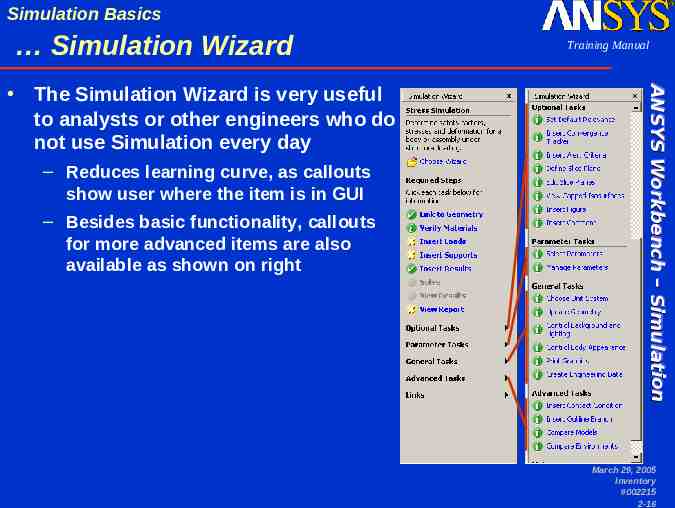
Simulation Basics Simulation Wizard – Reduces learning curve, as callouts show user where the item is in GUI – Besides basic functionality, callouts for more advanced items are also available as shown on right ANSYS Workbench – Simulation The Simulation Wizard is very useful to analysts or other engineers who do not use Simulation every day Training Manual March 29, 2005 Inventory #002215 2-16
Simulation Basics C. Basic Procedure Training Manual The purpose of simulation is usually to determine the response of the system based on some type of excitation or loading. It is crucial to remember that a mathematical model is used: – CAD geometry is an idealization of the physical model – The mesh is a mathematical representation of the CAD model – The accuracy of answers is determined by various factors: How well the physical model is represented depends on the assumptions Numerical accuracy is determined by the mesh density CAD Model Finite Element Mesh ANSYS Workbench – Simulation March 29, 2005 Inventory #002215 2-17
Simulation Basics Basic Procedure Every analysis involves four main steps: – Preliminary Decisions What type of analysis: Static, modal, etc.? Preliminary Decisions What to model: Part or Assembly? Which elements: Surface or Solid Bodies? – Preprocessing Preprocessing Attach the model geometry Define and assign material properties to parts Mesh the geometry Apply loads and supports Solution Request results – Solve the Model – Postprocessing Review results ANSYS Workbench – Simulation Training Manual Postprocessing Check the validity of the solution March 29, 2005 Inventory #002215 2-18
Simulation Basics Basic Procedure Training Manual The Wizards in Simulation aid the user in following the basic analysis template discussed previously, and these steps below will be covered in the next slides: – Attach/import geometry – Assign material properties – (Mesh geometry) A default mesh will be supplied by Simulation if this step is not performed manually by the user – Apply loads and supports – Request results ANSYS Workbench – Simulation A sample analysis using the Stress Wizard will be shown in this section. – Solve model – Review results/postprocessing March 29, 2005 Inventory #002215 2-19
Simulation Basics Attach Geometry Training Manual – Direct from CAD system For supported CAD packages only using plug-in mode – From within a blank Simulation session For all supported formats, using plug-in or reader mode Directly launches Simulation and attaches geometry (plug-in mode) Attaches active CAD model (plug-in mode) Browse for CAD file (reader mode) Method 1 Method 2 ANSYS Workbench – Simulation Earlier, it was shown that geometry can be attached to Simulation in two ways March 29, 2005 Inventory #002215 2-20
Simulation Basics Assign Material Properties Training Manual – “Verify Materials” is selected, and the callout shows how to change material properties in the pull-down menu After “Verify Materials” is selected, all of the parts from the “Geometry” branch are highlighted, and the Details view shows how to change the material. ANSYS Workbench – Simulation After importing a model, the Stress Branch template was chosen, and the Stress Wizard appears March 29, 2005 Inventory #002215 2-21
Simulation Basics Assign Material Properties Notice that the Details View allows the user to select a material from a pull-down menu – The default material property is “Structural Steel” but can be changed – By selecting “Import ” the user can select a material property file (XML format) – Although a few material properties are supplied with Simulation, as with any other input data, the user should use his/her own material data values. ANSYS Workbench – Simulation Training Manual March 29, 2005 Inventory #002215 2-22
Simulation Basics Assign Material Properties Training Manual – Note that the part name is obtained from the CAD model Multiple instances of the same part are differentiated by number – Multiple parts can be highlighted and changed at once Use Shift-Left mouse button to highlight all items in range Use Ctrl-Left mouse button to individually add/remove selection By using a combination of ShiftLeft mouse button and Ctrl-Left mouse button, twelve parts are highlighted on the Outline Tree The user can then change all materials at once in the Details View by selecting the material pull-down menu. ANSYS Workbench – Simulation Materials may be individually selected for each part Note that DesignSpace Entra is limited to analysis of single parts. ANSYS License DesignSpace Entra DesignSpace Professional Structural Mechanica l/Multiphysics Availability x x x x March 29, 2005 Inventory #002215 2-23
Simulation Basics Assign Material Properties ANSYS Workbench – Simulation Material properties are listed, modified, imported or exported by accessing the “Data” tab Training Manual March 29, 2005 Inventory #002215 2-24
Simulation Basics Assign Material Properties Training Manual – The default material can be changed from “Structural Steel” – Items to be always available in drop-down menu can be added – New materials can be added from various locations ANSYS Workbench – Simulation Default settings for material properties can be changed in the “Tools menu Options Simulation: Engineering Data” March 29, 2005 Inventory #002215 2-25
Simulation Basics Insert Loads & Supports Training Manual – Structural (and thermal) loads are applied from the pull-down icon in the Context toolbar. After “Insert Loads” is selected, notice that the “Environment” branch is highlighted. By highlighting the “Environment” branch, the Context toolbar and Details view change. ANSYS Workbench – Simulation After verifying and assigning materials, the “Insert Loads” item is selected from the Stress Wizard March 29, 2005 Inventory #002215 2-26
Simulation Basics Insert Loads & Supports Training Manual There are two ways to accomplish this: – Select geometry entity in Graphics Window first, then select load or support from Context Toolbar – Select load or support from Context Toolbar first, select geometry entities in Graphics Window, then click on “Apply” in Details View. ANSYS Workbench – Simulation Loads and supports are applied on geometric entities March 29, 2005 Inventory #002215 2-27
Simulation Basics Insert Loads & Supports Training Manual – Notice that, in the Outline Tree, the associated load branch symbol status will also change to ‘completed’ (checkmark) ANSYS Workbench – Simulation After assigning the load on geometric entities, the user can enter additional data in the Details view, if necessary. March 29, 2005 Inventory #002215 2-28
Simulation Basics Insert Loads & Supports For some structural loads, direction is often needed: – Selection is done in Details View of load If “Components” is chosen, enter X, Y, or Z Components of loading If “Vector” is chosen, select geometry and enter magnitude of loading Defaults can be set in “Tools Options Simulation: Miscellaneous Load Orientation Type” – The World Coordinate System can be referenced Direction is shown with triad in Graphics Window World Coordinate System orientation and origin from CAD system For this situation, use “Define By: Components” in “Details” view. Then enter x, y, and/or z components for load ANSYS Workbench – Simulation Training Manual (User-Defined Cartesian Coordinate Systems may also be used, as will be discussed later) March 29, 2005 Inventory #002215 2-29
Simulation Basics Insert Loads & Supports Training Manual In the “Details” view, select “Define By: Vector” to use existing geometry for vector orientation Three types of existing geometry can be used – Normal to planar face or along axis of cylindrical face – Along straight edge or normal to cylindrical edge – Two vertices defining vector Click on “Direction” and select geometry used for vector orientation. If vector is pointing in opposite direction, use the arrows in the Graphics window to toggle the direction. Click on “Apply” when done. Enter magnitude for loading in “Magnitude.” ANSYS Workbench – Simulation – On the other hand, existing geometry can be referenced: March 29, 2005 Inventory #002215 2-30
Simulation Basics Mouse Controls At this point, it will be useful to review mouse controls in the Graphics Window: – The left mouse button is used to select geometric entities OR to manipulate the graphics display Left mouse button behavior is controlled by Graphics Toolbar User can select items (vertex, edge, surface, body) or manipulate the view (rotate, pan, zoom in/out, box zoom) Select mode can be single-select or box-select – In single-select mode, click-drag with left mouse button to “paint select” multiple items – Use Ctrl-Left mouse button in single-select mode to select or unselect multiple entities – In box-select mode, click-drag from left to right selects entities fully enclosed in bounding box ANSYS Workbench – Simulation Training Manual – In box-select mode, click-drag from right to left selects any entity partially enclosed in bounding box March 29, 2005 Inventory #002215 2-31
Simulation Basics Mouse Controls Training Manual Click-drag middle mouse button to dynamically rotate model Shift-Middle mouse button pans model If present, the wheel can be used to zoom in/out (This way, user does not always have to toggle left mouse button between select mode and graphics manipulation mode) – The right mouse button provides context-sensitive pop-up menu if clicked once in Graphics Window Click-drag right mouse button to box zoom in area of interest Click right mouse button once and select “Fit” to fit model in view Click-drag right mouse button allows user to box-zoom in region Single-click right mouse button provides contextsensitive pop-up menu ANSYS Workbench – Simulation – In select mode, the middle mouse button changes view March 29, 2005 Inventory #002215 2-32
Simulation Basics Applying Loads and Supports Training Manual – In example below, user can use Ctrl-left mouse button to single-select surfaces (highlighted in green) – Use of middle mouse button allows user to rotate model to more easily select certain surfaces in ‘back’ of model ANSYS Workbench – Simulation By taking advantage of the mouse controls, it can be relatively easy to apply a load (or support) to multiple faces March 29, 2005 Inventory #002215 2-33
Simulation Basics Insert Results Training Manual – By selecting “Insert Results” in the Stress Wizard, the callout shows how to add results Note that the “Solution” branch is now highlighted. Because the “Solution” branch is selected, the Context toolbar and Details view changes. Results, such as stress, strain, and deformation can be requested from the pulldown icons on the Context toolbar. New result items will then appear under the “Solution” branch. ANSYS Workbench – Simulation By selecting the Stress Branch template in the beginning, some results are already requested. However, the user can request other results, if needed. March 29, 2005 Inventory #002215 2-34
Simulation Basics Solving the Model Training Manual – Selection of “Solve” in the Stress Wizard produces a callout showing the user that the lightning bolt icon is used to initiate a solution Starting the solution will include automatically meshing the model if it has not been done so previously. The solution may take a few minutes to a few hours, depending on how large the model is and the hardware used. A progress bar will be shown to indicate roughly how long the solution will take. The solution can also be stopped via the progress bar. ANSYS Workbench – Simulation After verifying materials, applying loads and supports, and inserting results, the model is ready to be solved. March 29, 2005 Inventory #002215 2-35
Simulation Basics Solving the Model (ANSYS Details) Training Manual – An ANSYS input file is generated, and the details of the Output File can be viewed if a “Solution Information” result branch has been requested under the “Solution” branch In Worksheet view of the “Solution Information” branch, the contents of the Output File will be updated with a frequency as specified in the Details view. The location of the input file “ds.dat,” output file “solve.out,” and scratch files are located in the system TEMP directory by default. This solver directory can be changed under “Tools Options Simulation: Solution Solver Working Directory” Advanced ANSYS Details ANSYS Workbench – Simulation For regular ANSYS users, it may be useful to note that the solution is performed in batch mode. March 29, 2005 Inventory #002215 2-36
Simulation Basics View Results Training Manual – The type of results is dependent on the analysis performed – Contour, vector plots, and animations can be viewed To view results, as the callout shows, the appropriate branch needs to be selected. ANSYS Workbench – Simulation After the solution is complete, the user can View Results March 29, 2005 Inventory #002215 2-37
Simulation Basics View Report Training Manual – Select a branch first, such as “Equivalent Stress” – Then select the appropriate Standard Toolbar button: ANSYS Workbench – Simulation In preparation for generating the HTML report, one can add figures and comments from the Standard Toolbar March 29, 2005 Inventory #002215 2-38
Simulation Basics View Report Training Manual – Preliminary information can be entered, such as author name – Select “Generate Report” to create HTML report The HTML Report can be selected under the “Solution” branch via “Report Preview” tab, as the callout indicates. ANSYS Workbench – Simulation After adding any figures or comments, select “View Report” March 29, 2005 Inventory #002215 2-39
Simulation Basics View Report – Comments and figures added will appear in the report The HTML report generator includes all input and results associated with the simulation, providing complete documentation of the analysis. This provides time-saving yet customizable report that can easily be generated by the user. ANSYS Workbench – Simulation The HTML report will be displayed in Simulation Training Manual March 29, 2005 Inventory #002215 2-40
Simulation Basics View Report Training Manual – The report can be “published” as HTML files in a different directory or an internal web server, emailed, or sent to Microsoft Word or PowerPoint The Appendix at the end of the HTML Report will show the location of the various files used to created the report. ANSYS Workbench – Simulation Reports are always dynamically generated, so the user needs to save the report, otherwise it will be overwritten March 29, 2005 Inventory #002215 2-41
Simulation Basics D. Workshop 2 Training Manual Goal: – Using the Stress Wizard, set up and solve a structural model for stress, deflection and safety factor. ANSYS Workbench – Simulation Workshop 2 – Simulation Basics March 29, 2005 Inventory #002215 2-42