DFD Examples Yong Choi BPA CSUB


20 Slides286.50 KB
DFD Examples Yong Choi BPA CSUB
Creating Data Flow Diagrams Steps: 1. Create a list of activities 2. Construct Context Level DFD (identifies external entities and processes) 3. Construct Level 0 DFD (identifies manageable sub process ) 4. Construct Level 1- n DFD (identifies actual data flows and data stores ) 5. Check against rules of DFD
DFD Naming Guidelines External Entity Noun Data Flow Names of data Process verb phrase – a system name – a subsystem name Data Store Noun
Creating Data Flow Diagrams Lemonade Stand Example
Creating Data Flow Diagrams Example The operations of a simple lemonade stand will be used to demonstrate the creation of dataflow diagrams. Steps: 1. Create a list of activities Old way: no Use-Case Diagram New way: use Use-Case Diagram 2. Construct Context Level DFD (identifies sources and sink) 3. Construct Level 0 DFD (identifies manageable sub processes ) 4. Construct Level 1- n DFD (identifies actual data flows and data stores )
Creating Data Flow Diagrams Example 1. Create a list of activities Think through the activities that take place at a lemonade stand. Customer Order Serve Product Collect Payment Produce Product Store Product
Creating Data Flow Diagrams Example 1. Create a list of activities Also think of the additional activities needed to support the basic activities. Customer Order Serve Product Collect Payment Produce Product Store Product Order Raw Materials Pay for Raw Materials Pay for Labor
Creating Data Flow Diagrams Example 1. Create a list of activities Group these activities in some logical fashion, possibly functional areas. Customer Order Serve Product Collect Payment Produce Product Store Product Order Raw Materials Pay for Raw Materials Pay for Labor
Creating Data Flow Diagrams Example Create a context level diagram identifying the sources and sinks (users). 2. Construct Context Level DFD (identifies sources and sink) Context Level DFD Order Customer Order Serve Product Collect Payment Produce Product Store Product Order Raw Materials Pay for Raw Materials Pay for Labor CUSTOMER Product Served Sales Forecast 0.0 Lemonade Production Schedule EMPLOYEE Pay System Payment Received Goods Payment VENDOR Time Worked Purchase Order
Creating Data Flow Diagrams Example Create a level 0 diagram identifying the logical subsystems that may exist. 3. Construct Level 0 DFD (identifies manageable sub processes ) Level 0 DFD 1.0 Sale Customer Order Serve Product Collect Payment Product Ordered Payment CUSTOMER Produce Product Store Product Order Raw Materials Pay for Raw Materials Pay for Labor Sales Forecast Customer Order Product Served Received Goods VENDOR Purchase Order Production Schedule 2.0 Production EMPLOYEE Inventory 3.0 Procurement Payment Order Decisions Pay 4.0 Payroll Time Worked
Creating Data Flow Diagrams Example Create a level 1 decomposing the processes in level 0 and identifying data stores. 4. Construct Level 1- n DFD (identifies actual data flows and data stores ) Level 1 DFD CUSTOMER Customer Order Customer Order Serve Product Collect Payment Produce Product Store Product Order Raw Materials Pay for Raw Materials Pay for Labor ORDER 1.1 Record Order Severed Order Payment 1.2 Receive Payment PAYMENT Request for Forecast 1.3 Produce Sales Forecast Sales Forecast
Creating Data Flow Diagrams Example Create a level 1 decomposing the processes in level 0 and identifying data stores. 4. Construct Level 1 (continued) Level 1 DFD Product Order ORDER Customer Order Serve Product Collect Payment Produce Product Store Product Order Raw Materials Pay for Raw Materials Pay for Labor 2.1 Serve Product Quantity Severed RAW MATERIALS Production Schedule 2.2 Produce Product Production Data 2.3 Store Product Quantity Used INVENTORTY Quantity Produced & Location Stored
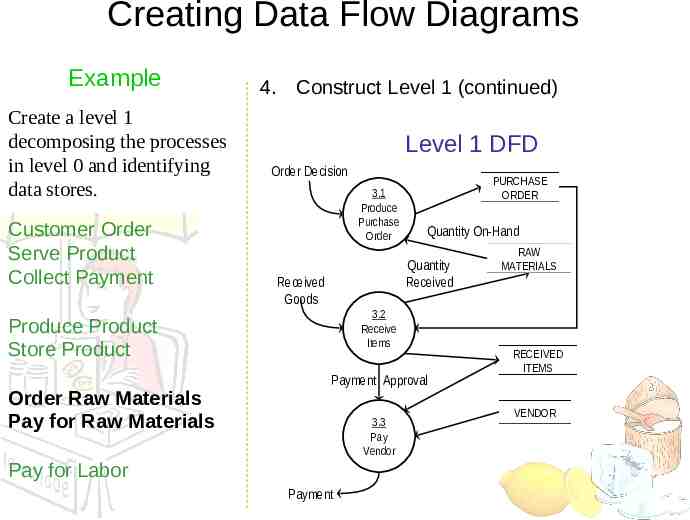
Creating Data Flow Diagrams Example Create a level 1 decomposing the processes in level 0 and identifying data stores. Customer Order Serve Product Collect Payment 4. Construct Level 1 (continued) Level 1 DFD Order Decision 3.1 Produce Purchase Order Quantity On-Hand Quantity Received Received Goods 3.2 Receive Items Produce Product Store Product Order Raw Materials Pay for Raw Materials PURCHASE ORDER Payment Approval 3.3 Pay Vendor Pay for Labor Payment RAW MATERIALS RECEIVED ITEMS VENDOR
Creating Data Flow Diagrams Example Create a level 1 decomposing the processes in level 0 and identifying data stores. Customer Order Serve Product Collect Payment 4. Construct Level 1 (continued) Level 1 DFD Time Worked 4.1 Record Time Worked TIME CARDS Employee ID EMPLOYEE Payroll Request 4.2 Calculate Payroll Produce Product Store Product Unpaid time cards PAYROLL Payment Approval Order Raw Materials Pay for Raw Materials 4.3 Pay Employe e Pay for Labor Payment PAYMENTS
Process Decomposition 0.0 Lemonade System Context Level 1.0 Sale 1.1 Record Order 1.2 Receive Payment 2.0 Production 2.1 Serve Product 2.2 Produce Product 2.3 Store Product 3.0 Procurement 3.1 Produce Purchase Order 3.2 Receive Items 3.3 Pay Vendor 4.0 Payroll 4.1 Record Time Worked 4.2 Calculate Payroll 4.3 Pay Employe e Level 0 Level 1
DFD Example: Bus Garage Repairs Buses come to a garage for repairs. A mechanic and helper perform the repair, record the reason for the repair and record the total cost of all parts used on a Shop Repair Order. Information on labor, parts and repair outcome is used for billing by the Accounting Department, parts monitoring by the inventory management computer system and a performance review by the supervisor.
DFD Example: Bus Garage Repairs (cont’d) External Entities: Bus, Mechanic, Helper, Supervisor, Inventory Management System, Accounting Department, etc. Key process (“the system”): performing repairs and storing information related to repairs Processes: – – – – – Record Bus ID and reason for repair Determine parts needed Perform repair Calculate parts extended and total cost Record labor hours, cost
DFD Example: Bus Garage Repairs (cont’d) Data stores: – – – – Personnel file Repairs file Bus master list Parts list Data flows: – – – – – Repair order Bus record Parts record Employee timecard Invoices
Bus Garage Context Diagram Bus Fixed mechanical problems Mechanical problem to be repaired Helper Labor Bus Repair Process System Labor Mechanic Labor, parts cost details Repair summary List of parts used Supervisor Inventory Management System Accounting
CSUB Burger’s Order Processing System Draw the CSUB Burger’s context diagram – System Order processing system – External entities Kitchen Restaurant Customer – Processes Customer order Receipt Food order Management report