CSCI 4717/5717 Computer Architecture Topic: Input/Output Reading:


51 Slides282.50 KB
CSCI 4717/5717 Computer Architecture Topic: Input/Output Reading: Stallings, Chapter 7 CSCI 4717 – Computer Architecture Input/Output– Page 1 of 51
General Description of I/O Wide variety of peripherals Delivering different amounts of data At different speeds In different formats (bit depth, etc.) CSCI 4717 – Computer Architecture Input/Output– Page 2 of 51
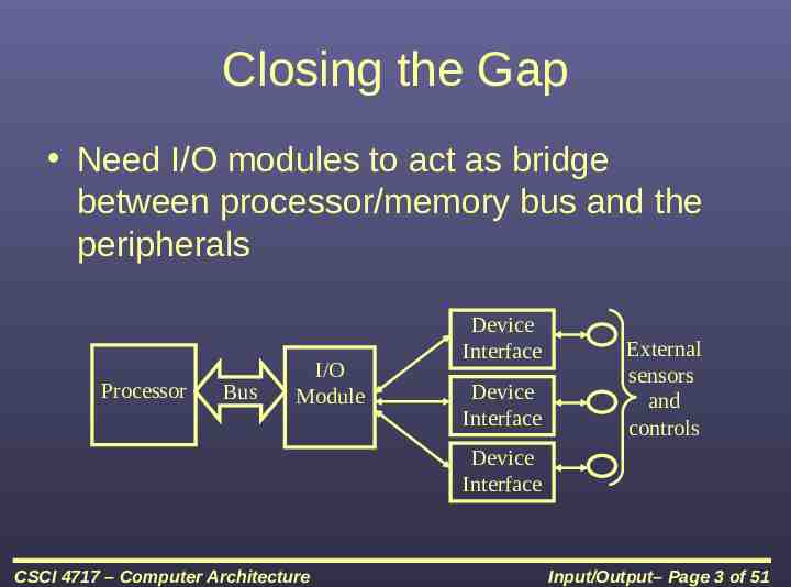
Closing the Gap Need I/O modules to act as bridge between processor/memory bus and the peripherals Processor Bus I/O Module Device Interface Device Interface External sensors and controls Device Interface CSCI 4717 – Computer Architecture Input/Output– Page 3 of 51
External Devices External devices are needed as a means of communication to the outside world (both input and output – I/O) Types – Human readable – communication with user (monitor, printer, keyboard, mouse) – Machine readable – communication with equipment (hard drive, CDROM, sensors, and actuators) – Communication – communication with remote computers/devices (Can be any of the first two or a network interface card or modem) CSCI 4717 – Computer Architecture Input/Output– Page 4 of 51
Generic Device Interface Configuration CSCI 4717 – Computer Architecture Input/Output– Page 5 of 51
Device Interface Components The control logic is the I/O module's interface to the device The data channel passes the collected data from or the data to be output to the device. On the opposite end is the I/O module, but eventually it is the processor. The transducer acts as a converter between the digital data of the I/O module and the signals of the outside world. – Keyboard converts motion of key into data representing key pressed or released – Temperature sensor converts amount of heat into a digital value – Disk drive converts data to electronic signals for controlling the read/write head CSCI 4717 – Computer Architecture Input/Output– Page 6 of 51
I/O Module Functions Control & Timing Processor Communication Device Communication Data Buffering Error Detection CSCI 4717 – Computer Architecture Input/Output– Page 7 of 51
I/O Module: Control and Timing Required because of multiple devices all communicating on the same channel Example – CPU checks I/O module device status – I/O module returns status – If ready, CPU requests data transfer – I/O module gets data from device – I/O module transfers data to CPU – Variations for output, DMA, etc. CSCI 4717 – Computer Architecture Input/Output– Page 8 of 51
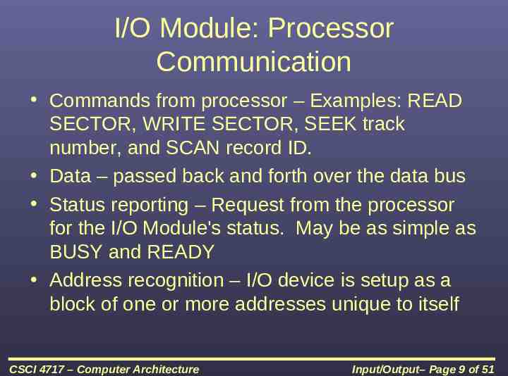
I/O Module: Processor Communication Commands from processor – Examples: READ SECTOR, WRITE SECTOR, SEEK track number, and SCAN record ID. Data – passed back and forth over the data bus Status reporting – Request from the processor for the I/O Module's status. May be as simple as BUSY and READY Address recognition – I/O device is setup as a block of one or more addresses unique to itself CSCI 4717 – Computer Architecture Input/Output– Page 9 of 51
Other I/O Module Functions Device Communication – specific to each device Data Buffering – Due to the differences in speed (device is usually orders of magnitude slower) the I/O module needs to buffer data to keep from tying up the CPU's bus with slow reads or writes Error Detection – simply distributing the need for watching for errors to the module. They may include: – Malfunctions by device (paper jam) – Data errors (parity checking at the device level) – Internal errors to the I/O module such as buffer overruns CSCI 4717 – Computer Architecture Input/Output– Page 10 of 51
I/O Module Structure CSCI 4717 – Computer Architecture Input/Output– Page 11 of 51
I/O Module Level of Operation How much control will the CPU be required to handle? How much will the CPU be allowed to handle? What will the interface look like, e.g., Unix treats everything like a file Support multiple or single device Will additional control be needed for multiple devices on a single port (e.g., serial port versus USB) CSCI 4717 – Computer Architecture Input/Output– Page 12 of 51
Input/Output Techniques Programmed I/O – poll and response Interrupt driven – module calls for CPU when needed Direct Memory Access (DMA) – module has direct access to specified block of memory CSCI 4717 – Computer Architecture Input/Output– Page 13 of 51
Addressing I/O Devices “Memory-Mapped I/O” Data transfer is the same as a memory access (chip selects) 80x86 example, any assembly language command accessing memory use memory read ( MRDC) and write ( MWTC) lines Can use ALL memory instructions which is much greater than I/O instructions CSCI 4717 – Computer Architecture Input/Output– Page 14 of 51
Addressing I/O Devices “Isolated I/O” Data transfer uses the same address lines but different read/write control lines 8086 example, in and out commands use same bus with different read ( IORC) and write ( IOWC) lines Limited number of instructions to choose from CSCI 4717 – Computer Architecture Input/Output– Page 15 of 51
Programmed I/O – CPU has direct control over I/O Processor requests operation with commands sent to I/O module – Control – telling a peripheral what to do – Test – used to check condition of I/O module or device – Read – obtains data from peripheral so processor can read it from the data bus – Write – sends data using the data bus to the peripheral I/O module performs operation When completed, I/O module updates its status registers Sensing status – involves polling the I/O module's status registers CSCI 4717 – Computer Architecture Input/Output– Page 16 of 51
Programmed I/O (continued) I/O module does not inform CPU directly CPU may wait or do something and come back later Wastes CPU time because typically processor is much faster than I/O – CPU acts as a bridge for moving data between I/O module and main memory, i.e., every piece of data goes through CPU – CPU waits for I/O module to complete operation CSCI 4717 – Computer Architecture Input/Output– Page 17 of 51
Programmed I/O Example Motorola 68HC11 Serial Communications Memory-mapped control registers – SCCR1(0x102C) R8 T8 M WAKE 0 0 ILIE TE RE RWU 0 0 – SCCR2 (0x102D) TIE TCIE RIE Memory-mapped status register SCSR (0x102E) TDRE TC RDRF CSCI 4717 – Computer Architecture IDLE OR NF FE 0 Input/Output– Page 18 of 51
Programmed I/O Example (continued) Control: Transmit enable (TE) – Set to one in order to enable serial output Receive enable (RE) – Set to one in order to enable serial input Status: Transmit data register empty (TDRE) – Set to one to indicate data can be placed in buffer Transmit complete (TC) – zero means character is being sent; one means transmitter idle Receive data register full – Set to a one when received data needs to be read CSCI 4717 – Computer Architecture Input/Output– Page 19 of 51
Programmed I/O Example (continued) “Transmitting a character” SCCR2 0x08; // Set TE to 1 while !end of stream { while !(SCSR & 0x80); // Wait until TDRE 1 SCDR next byte to send; } CSCI 4717 – Computer Architecture Input/Output– Page 20 of 51
Programmed I/O Example (continued) “Receiving a character” SCCR2 0x04; // Set RE to 1 while !(SCSR & 0x20); // Wait until RDRF 1 received byte SCDR; CSCI 4717 – Computer Architecture Input/Output– Page 21 of 51
Interrupt Driven I/O Overcomes CPU waiting Requires setup code and interrupt service routine No repeated CPU checking of device I/O module interrupts when ready Still requires CPU to be go between for moving data between I/O module and main memory CSCI 4717 – Computer Architecture Input/Output– Page 22 of 51
Analogy: Exception Handling Before exception handling, functions would indicate an error with a return value – Calling code would check return code and handle error accordingly – Code littered with extra if-statements – Ex: if(myFunction() -1) printf("Error occurred."); Exception handling creates some sort of error flag. – Third party code watches for flag, and if it gets set, executes error handler. – Allows for single error handler and cleaner code Configuration consists of trigger, listener, and handler CSCI 4717 – Computer Architecture Input/Output– Page 23 of 51
Basic Interrupt I/O Operation CPU initializes the process I/O module gets data from peripheral while CPU does other work I/O module interrupts CPU CPU requests data I/O module transfers data CSCI 4717 – Computer Architecture Input/Output– Page 24 of 51
CPU Viewpoint CSCI 4717 – Computer Architecture Input/Output– Page 25 of 51
CPU Viewpoint (continued) Issue read command Do other work Check for interrupt at end of each instruction cycle (NO CODE IS INVOLVED IN THIS) I/O module issues interrupt request CSCI 4717 – Computer Architecture Input/Output– Page 26 of 51
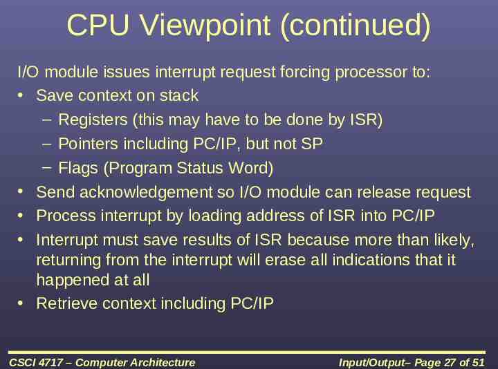
CPU Viewpoint (continued) I/O module issues interrupt request forcing processor to: Save context on stack – Registers (this may have to be done by ISR) – Pointers including PC/IP, but not SP – Flags (Program Status Word) Send acknowledgement so I/O module can release request Process interrupt by loading address of ISR into PC/IP Interrupt must save results of ISR because more than likely, returning from the interrupt will erase all indications that it happened at all Retrieve context including PC/IP CSCI 4717 – Computer Architecture Input/Output– Page 27 of 51
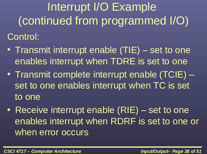
Interrupt I/O Example (continued from programmed I/O) Control: Transmit interrupt enable (TIE) – set to one enables interrupt when TDRE is set to one Transmit complete interrupt enable (TCIE) – set to one enables interrupt when TC is set to one Receive interrupt enable (RIE) – set to one enables interrupt when RDRF is set to one or when error occurs CSCI 4717 – Computer Architecture Input/Output– Page 28 of 51
Interrupt I/O Example (continued) Status: Overrun error (OR) – set to one when character received but there was no room in SCDR Noise flag (NF) – set to one when noise is detected on receive input Framing error (FE) – set to one when received data had error with framing bits CSCI 4717 – Computer Architecture Input/Output– Page 29 of 51
Interrupt I/O Example (continued) “Transmitting a character” SCCR2 0x88; // Set TIE and TE to 1 setISR(&ser tx ISR()); // At this point, processor can do something else void INTERRUPT ser tx ISR() { SCDR next byte to send; } CSCI 4717 – Computer Architecture Input/Output– Page 30 of 51
Interrupt I/O Example (continued) “Receiving a character” SCCR2 0x24; // Set RIE and RE to 1 setISR(&ser rx ISR()); // At this point, processor can do something else void INTERRUPT ser rx ISR() { if ((SCSR & 0x2E) 0x20) received byte SCDR; else if ((SCSR & 0xE) ! 0) process error(); } CSCI 4717 – Computer Architecture Input/Output– Page 31 of 51
Design Issues Resolution of multiple interrupts – How do you identify the module issuing the interrupt? Priority – How do you deal with multiple interrupts at the same time or interrupting in the middle of an interrupt? CSCI 4717 – Computer Architecture Input/Output– Page 32 of 51
Identifying Interrupting Module Different interrupt line for each module Limits number of devices Even with this method, there are often multiple interrupts still on a single interrupt lined Priority is set by hardware CSCI 4717 – Computer Architecture Input/Output– Page 33 of 51
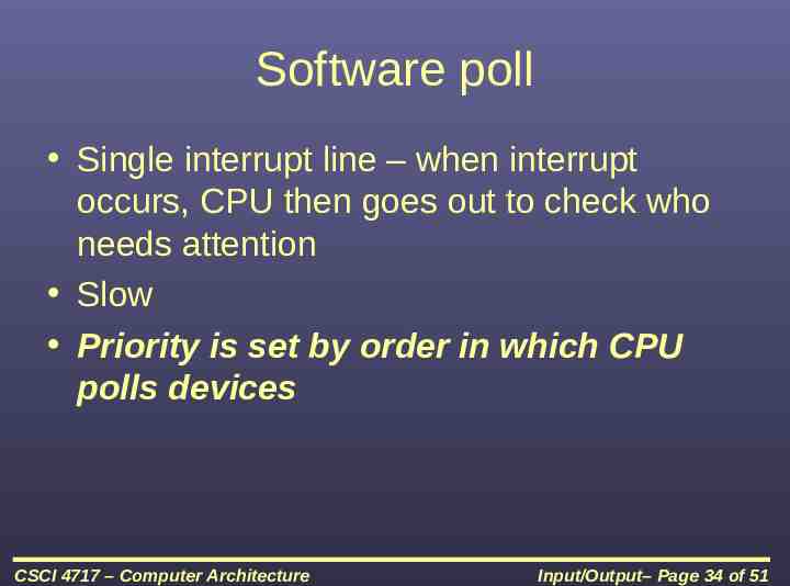
Software poll Single interrupt line – when interrupt occurs, CPU then goes out to check who needs attention Slow Priority is set by order in which CPU polls devices CSCI 4717 – Computer Architecture Input/Output– Page 34 of 51
Daisy Chain or Hardware poll Interrupt Acknowledge sent down a chain Module responsible places unique vector on bus CPU uses vector to identify handler routine Priority is set by order in which interrupt acknowledge gets to I/O modules, i.e., order of devices on the chain CSCI 4717 – Computer Architecture Input/Output– Page 35 of 51
Bus Arbitration Allow multiple modules to control bus (See “Method of Arbitration,” p. 75) I/O Module must claim the bus before it can raise interrupt Can do this with: – Bus controller/arbiter – Distribute control to devices Must be one master, either processor or other device Device that "wins" places vector on bus uniquely identifying interrupt Priority is set by priority in arbitration, i.e., whoever is currently in control of the bus CSCI 4717 – Computer Architecture Input/Output– Page 36 of 51
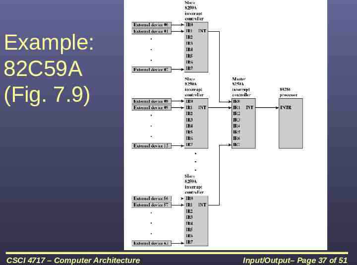
Example: 82C59A (Fig. 7.9) CSCI 4717 – Computer Architecture Input/Output– Page 37 of 51
82C59A (continued) 80386 has one interrupt line 8259A has 8 interrupt lines CSCI 4717 – Computer Architecture Input/Output– Page 38 of 51
82C59A Sequence of Events 82C59A accepts interrupts 82C59A determines priority – Fully nested IR0 (highest) through IR7 (lowest) – Rotating – after interrupt is serviced, it goes to bottom of priority list – Special mask – allows individual interrupts to be disabled 82C59A signals 8086 (raises INTR line) CPU Acknowledges with INTA line 82C59A puts correct vector on data bus CPU processes interrupt CSCI 4717 – Computer Architecture Input/Output– Page 39 of 51
Direct Memory Access (DMA) Impetus behind DMA – Interrupt driven and programmed I/O require active CPU intervention (All data must pass through CPU) Transfer rate is limited by processor's ability to service the device CPU is tied up managing I/O transfer CSCI 4717 – Computer Architecture Input/Output– Page 40 of 51
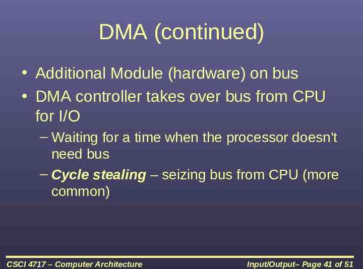
DMA (continued) Additional Module (hardware) on bus DMA controller takes over bus from CPU for I/O – Waiting for a time when the processor doesn't need bus – Cycle stealing – seizing bus from CPU (more common) CSCI 4717 – Computer Architecture Input/Output– Page 41 of 51
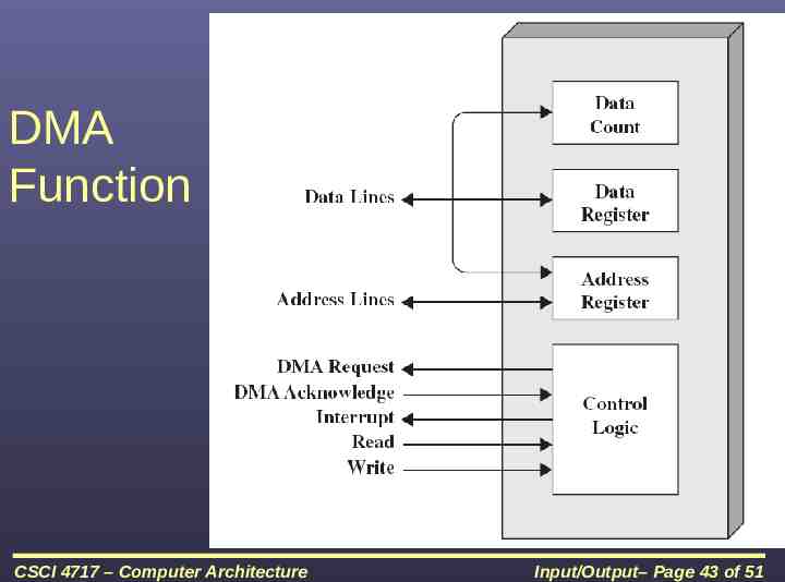
DMA Operation CPU tells DMA controller: – whether it will be a read or write operation – the address of device to transfer data from – the starting address of memory block for the data transfer – the amount of data to be transferred DMA performs transfer while CPU does other processes DMA sends interrupt when completed CSCI 4717 – Computer Architecture Input/Output– Page 42 of 51
DMA Function CSCI 4717 – Computer Architecture Input/Output– Page 43 of 51
Cycle Stealing DMA controller takes over bus for a cycle Transfer of one word of data Not an interrupt – CPU does not switch context CPU suspended just before it accesses bus – i.e. before an operand or data fetch or a data write Slows down CPU but not as much as CPU doing transfer CSCI 4717 – Computer Architecture Input/Output– Page 44 of 51
In-class discussion What effect does caching memory have on DMA? Hint: How much are the system buses available? CSCI 4717 – Computer Architecture Input/Output– Page 45 of 51
DMA Configurations Single Bus, Detached DMA controller – Each transfer uses bus twice – I/O to DMA then DMA to memory – CPU is suspended twice CSCI 4717 – Computer Architecture Input/Output– Page 46 of 51
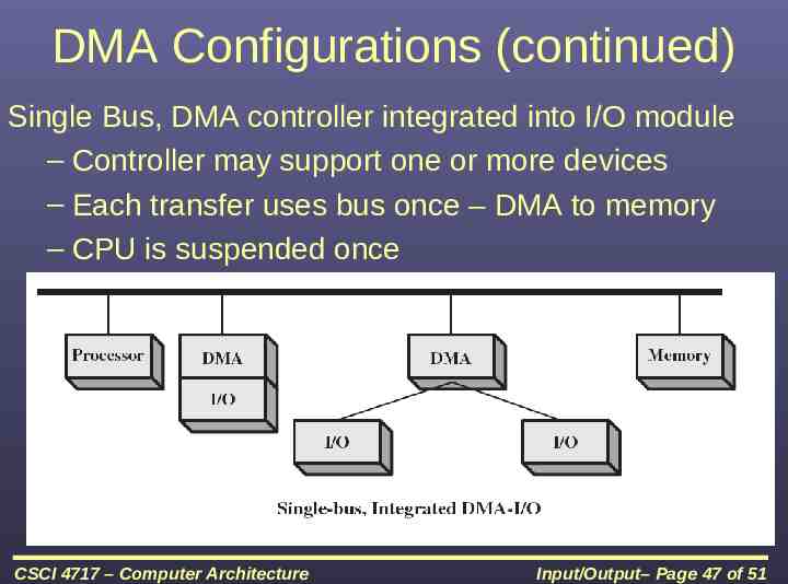
DMA Configurations (continued) Single Bus, DMA controller integrated into I/O module – Controller may support one or more devices – Each transfer uses bus once – DMA to memory – CPU is suspended once CSCI 4717 – Computer Architecture Input/Output– Page 47 of 51
DMA Configurations (continued) Separate I/O Bus – Bus supports all DMA enabled devices with single DMA controller – Each transfer uses bus once – DMA to memory – CPU is suspended once CSCI 4717 – Computer Architecture Input/Output– Page 48 of 51
Evolutions of I/O Methods Growth of more sophisticated I/O devices 1. Processor directly controls device 2. Processor uses Programmed I/O 3. Processor uses Interrupts 4. Processor uses DMA 5. Some processing moved to processors in I/O module that access programs in memory and execute them on their own without CPU intervention (I/O Module referred to as an I/O Channel) 6. Distributed processing where I/O module is a computer in its own right(I/O Module referred to as an I/O Processor) CSCI 4717 – Computer Architecture Input/Output– Page 49 of 51
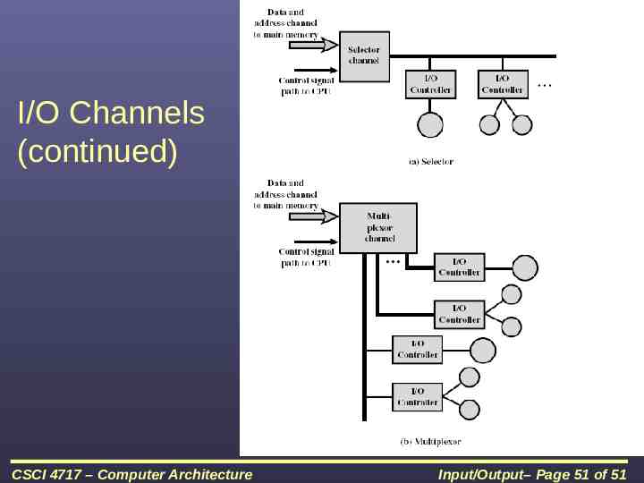
I/O Channels (continued) I/O Channel is extension of DMA concept CPU instructs the I/O channel to execute a program in memory Following these instructions, the I/O channel does the transfer of data itself Architecture – Selector – one device transferring block of data at a time – Multiplexor – TDM CSCI 4717 – Computer Architecture Input/Output– Page 50 of 51
I/O Channels (continued) CSCI 4717 – Computer Architecture Input/Output– Page 51 of 51