CS 425/625 Software Engineering Software Requirements Based on Chapter
26 Slides362.50 KB
CS 425/625 Software Engineering Software Requirements Based on Chapter 5 of the textbook [Somm00] Ian Sommerville, Software Engineering, 6th Ed., Addison-Wesley, 2000 and on Ch5 PowerPoint presentation from the book’s web-site: www.comp.lancs.ac.uk/computing/resources/IanS/SE6/Slides/index.html September 17, 2003 1 / 26
Outline Requirements: 2 / 26 Functional Non-functional Domain User Requirements Systems Requirements The Software Requirements Document
Requirements: Introduction 3 / 26 Requirements services the system is expected to provide constraints placed on the system Requirements engineering gathering, negotiating, analyzing, and documenting requirements The requirements could be expressed at various levels of abstraction The way requirements are defined has a major impact on the development of the software product
Requirements: .Introduction. A classification of requirements: 4 / 26 User requirements: higher level description of services requested and constraints imposed System requirements: a more detailed, structured description of services and constraints. Usually included in the contract between the developer and the client An even more detailed description of requirements can be provided in a software design specification (closer to implementation)
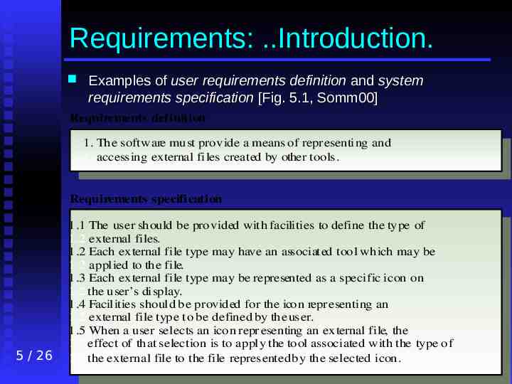
Requirements: .Introduction. Examples of user requirements definition and system requirements specification [Fig. 5.1, Somm00] Requirements definition 1. The software must provide a means of repr esenting and 1. accessing external files created by other tools. Requirements specification 5 / 26 1.1 The user should be provided with facilities to define the type of 1.2 external files. 1.2 Each external file type may have an associated tool which may be 1.2 applied to the file. 1.3 Each external file type may be represented as a specific icon on 1.2 the user’s display. 1.4 Facilities should be provided for the icon repr esenting an 1.2 external file type to be defined by the user. 1.5 When a user selects an icon repr esenting an external file, the 1.2 effect of that selection is to apply the tool associated with the type of 1.2 the external file to the file represented by the selected icon.
Requirements: Introduction Types of software system requirements: 6 / 26 Functional requirements, describe the requested functionality/behaviour of the system: services (functions), reactions to inputs, exceptions, modes of operations Non-functional requirements, represent constraints on the system and its functionality: performance constraints, compliance with standards, constraints on the development process Domain requirements, can be either functional or non-functional and reflect the particularities of the application domain
Requirements: Functional Functional requirements: Depend on the system, the software, and the users Can be expressed at different levels of detail (user/system requirements) For a system, it is desirable to have a complete and consistent set of functional requirements Completeness: all required system facilities are defined Consistency: there are no contradictions in requirements 7 / 26
Requirements: Non-functional. Non-functional requirements: Kinds of non-functional requirements: 8 / 26 Many apply to the system as a whole More critical than individual functional requirements More difficult to verify Product requirements Organizational requirements External requirements
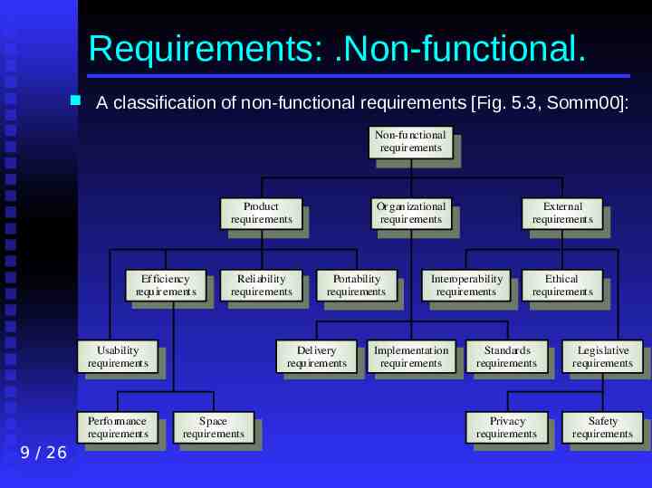
Requirements: .Non-functional. A classification of non-functional requirements [Fig. 5.3, Somm00]: Non-functional requir ements Product requir ements Ef ficiency requir ements Reliability requir ements Usability requirements Performance requirements 9 / 26 Or ganizational requir ements Portability requirements Delivery requirements Space requir ements External requirements Interoperability requirements Implementation requir ements Ethical requirements Standards requirements Legislative requirements Privacy requirements Safety requirements
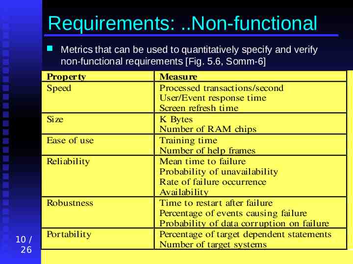
Requirements: .Non-functional Metrics that can be used to quantitatively specify and verify non-functional requirements [Fig. 5.6, Somm-6] Property Speed Size Ease of use Reliability Robustness 10 / 26 Portability Measure Processed transactions/second User/Event response time Screen refresh time K Bytes Number of RAM chips Training time Number of help frames Mean time to failure Probability of unavailability Rate of failure occurrence Availability Time to restart after failure Percentage of events causing failure Probability of data corruption on failure Percentage of target dependent statements Number of target systems
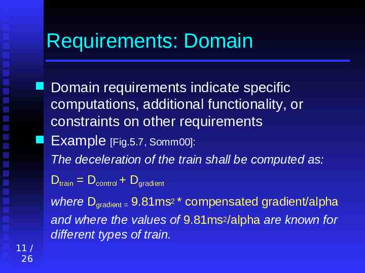
Requirements: Domain Domain requirements indicate specific computations, additional functionality, or constraints on other requirements Example [Fig.5.7, Somm00]: The deceleration of the train shall be computed as: Dtrain Dcontrol Dgradient where Dgradient 9.81ms2 * compensated gradient/alpha and where the values of 9.81ms2/alpha are known for different types of train. 11 / 26
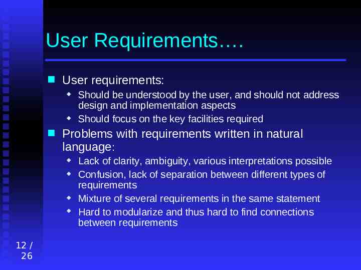
User Requirements . User requirements: Problems with requirements written in natural language: 12 / 26 Should be understood by the user, and should not address design and implementation aspects Should focus on the key facilities required Lack of clarity, ambiguity, various interpretations possible Confusion, lack of separation between different types of requirements Mixture of several requirements in the same statement Hard to modularize and thus hard to find connections between requirements
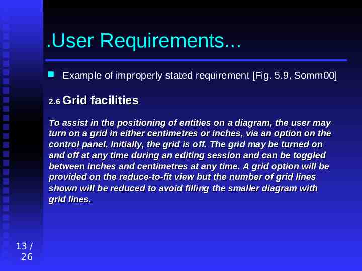
.User Requirements. Example of improperly stated requirement [Fig. 5.9, Somm00] 2.6 Grid facilities To assist in the positioning of entities on a diagram, the user may turn on a grid in either centimetres or inches, via an option on the control panel. Initially, the grid is off. The grid may be turned on and off at any time during an editing session and can be toggled between inches and centimetres at any time. A grid option will be provided on the reduce-to-fit view but the number of grid lines shown will be reduced to avoid filling the smaller diagram with grid lines. 13 / 26
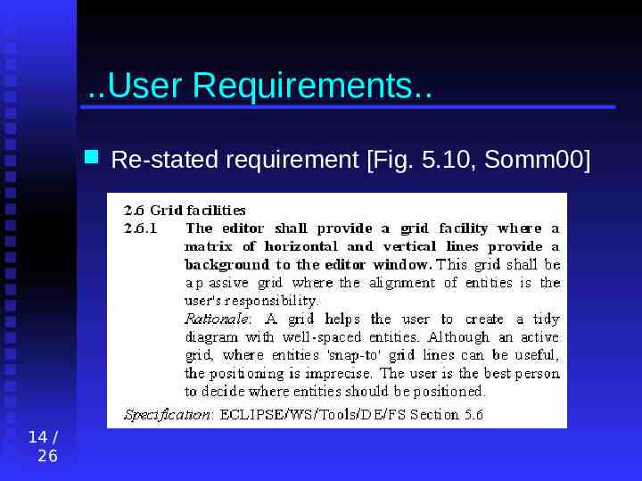
.User Requirements. 14 / 26 Re-stated requirement [Fig. 5.10, Somm00]
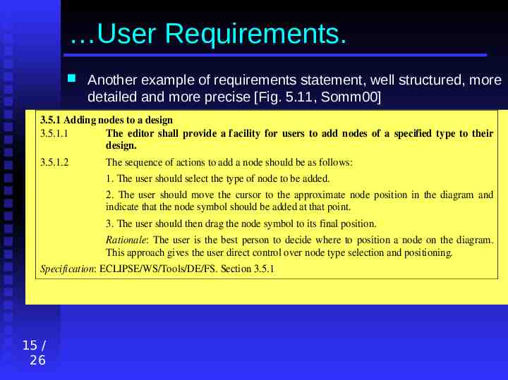
User Requirements. Another example of requirements statement, well structured, more detailed and more precise [Fig. 5.11, Somm00] 3.5.1 Adding nodes to a design 3.5.1.1 The editor shall provide a f acility for users to add nodes of a specified type to their design. 3.5.1.2 The sequence of actions to add a node should be as follows: 1. The user should select the type of node to be added. 2. The user should move the cursor to the approximate node position in the diagram and indicate that the node symbol should be added at that point. 3. The user should then drag the node symbol to its final position. Rationale: The user is the best person to decide where to position a node on the diagram. This approach gives the user direct control over node type selection and positioning. Specification: ECLIPSE/WS/Tools/DE/FS. Section 3.5.1 15 / 26
.User Requirements Guidelines for writing requirements: 16 / 26 Create and use a standard format for the entire software requirements specification Highlight important parts of the requirement statements Use consistently the language (difference between “should” and “shall”) Avoid computer jargon
System Requirements System requirements: 17 / 26 More detailed specifications of user requirements Included in the contract with the client Used by developers as basis for design May be specified using various models (object-oriented models, data-flow diagrams, formal specs, etc.) Should indicate WHAT the system is required to do (not HOW) and under what conditions and constraints
.System Requirements. . There is nevertheless a blurred line between specification and design because: 18 / 26 A system architecture may be needed to structure the requirements specification Design constraints may be part of the system requirements Factors such as interoperability may also impose design constraints
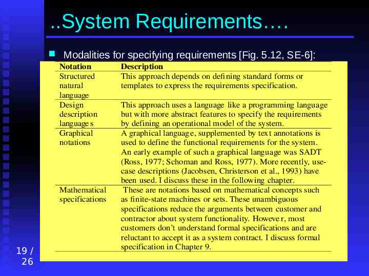
.System Requirements . Modalities for specifying requirements [Fig. 5.12, SE-6]: Notation Structured natural language Design description language s Graphical notations Mathematical specifications 19 / 26 Description This approach depends on defining standard forms or templates to express the requirements specification. This approach uses a language like a programming language but with more abstract features to specify the requirements by defining an operational model of the system. A graphical languag e, supplemented by text annotations is used to define the functional requirements for the system. An early example of such a graphical language was SADT (Ross, 1977; Schoman and Ross, 1977). More recently, usecase descriptions (Jacobsen, Christerson et al., 1993) have been used. I discuss these in the following chapter. These are notations based on mathematical concepts such as finite-state machines or sets. These unambiguous specifications reduce the arguments between customer and contractor about system functionality. Howeve r, most customers don’t understand formal specifications and are reluctant to accept it as a system contract. I discuss formal specification in Chapter 9.
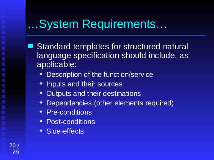
System Requirements Standard templates for structured natural language specification should include, as applicable: 20 / 26 Description of the function/service Inputs and their sources Outputs and their destinations Dependencies (other elements required) Pre-conditions Post-conditions Side-effects
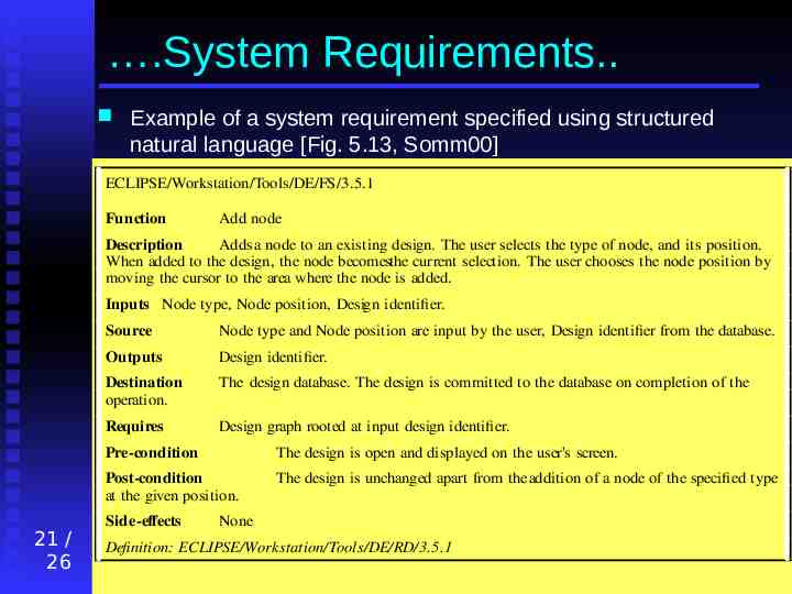
.System Requirements. Example of a system requirement specified using structured natural language [Fig. 5.13, Somm00] ECLIPSE/Workstation/Tools/DE/FS/3.5.1 Function Add node Description Adds a node to an existing design. The user selects the type of node, and its position. When added to the design, the node becomesthe current selection. The user chooses the node position by moving the cursor to the area where the node is added. Inputs Node type, Node position, Design identifier. 21 / 26 Source Node type and Node position are input by the user, Design identifier from the database. Outputs Design identifier. Destination operation. The design database. The design is committed to the database on completion of the Requires Design graph rooted at input design identifier. Pre-condition The design is open and displayed on the user's screen. Post-condition at the given position. The design is unchanged apart from the addition of a node of the specified type Side-effects None Definition: ECLIPSE/Workstation/Tools/DE/RD/3.5.1
.System Requirements. Another alternative to natural language (NL) for software specification is Program Description Languages (PDL) 22 / 26 Derived from programming languages May contain more abstract constructs Their syntax and semantics could be checked Recommended for describing sequences of actions whose order is important & for specifying software interfaces However, PDL specification require advised readers, can be taken as design specs, and may not be expressive enough
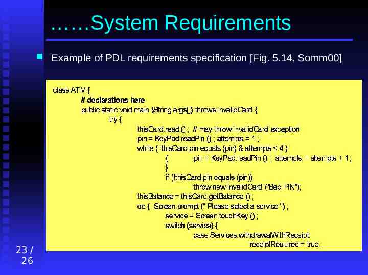
System Requirements 23 / 26 Example of PDL requirements specification [Fig. 5.14, Somm00]
The Software Requirements Document. This document, also called Software Requirements Specification (SRS), is the official description of the system’s requirements (includes user and system reqs.) Heninger (1980) recommends that an SRS should: 24 / 26 Specify only external system behaviour Specify constraints on implementation Be easy to change Serve as a reference for maintainers Record forethought about the software life cycle Describe acceptable responses to undesired events
.The System Requirements Document. SRS structure according IEEE/ANSI 830-1993 standard (overview only, many more details are given in the standard): 25 / 26 Introduction General description Specific requirements Appendices Index This structure needs to be tailored for each particular organization
.The System Requirements Document A more detailed structure suggested in [Fig. 5.17, Somm00]: 26 / 26 Table of contents Preface Introduction Glossary User requirements definition System architecture System requirements specification System models System evolution Appendices Index