Chapter 32 Inductance
68 Slides2.12 MB
Chapter 32 Inductance
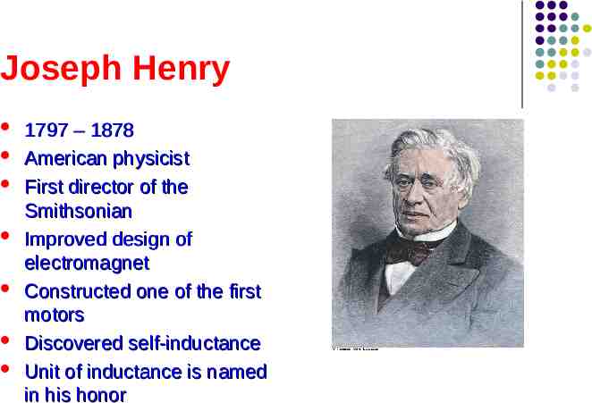
Joseph Henry 1797 – 1878 American physicist First director of the Smithsonian Improved design of electromagnet Constructed one of the first motors Discovered self-inductance Unit of inductance is named in his honor
Some Terminology Use emf and current when they are caused by batteries or other sources Use induced emf and induced current when they are caused by changing magnetic fields When dealing with problems in electromagnetism, it is important to distinguish between the two situations
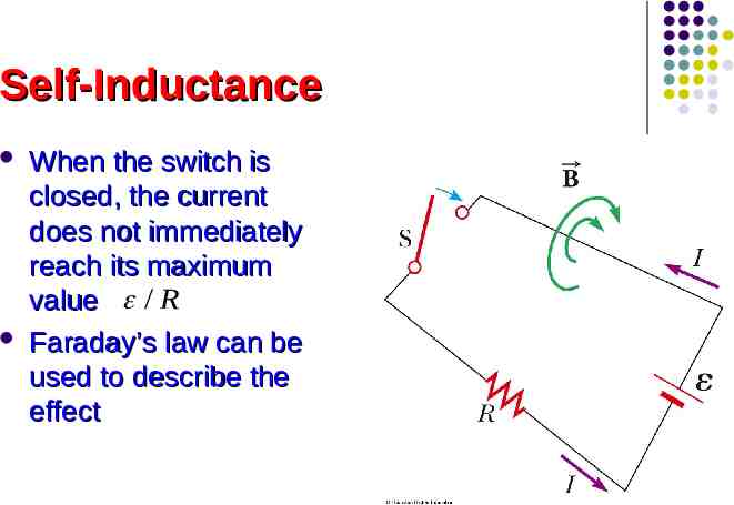
Self-Inductance When the switch is closed, the current does not immediately reach its maximum value / R Faraday’s law can be used to describe the effect
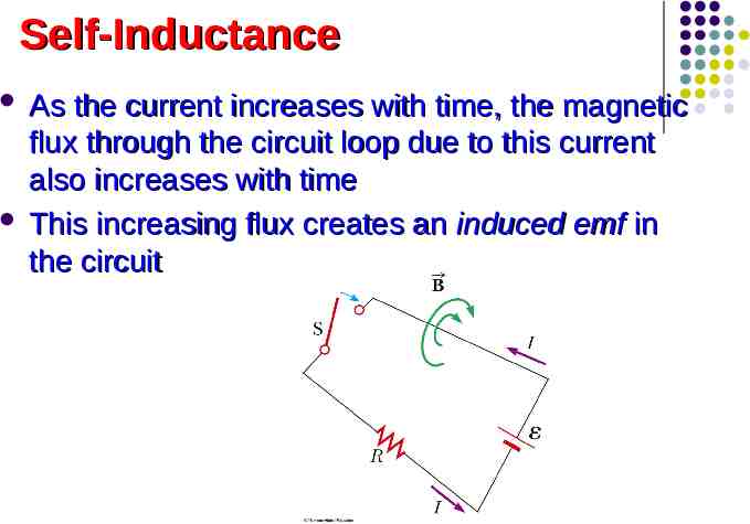
Self-Inductance As the current increases with time, the magnetic flux through the circuit loop due to this current also increases with time This increasing flux creates an induced emf in the circuit
Self-Inductance The direction of the induced emf is such that it would cause an induced current in the loop which would establish a magnetic field opposing the change in the original magnetic field The direction of the induced emf is opposite the direction of the emf of the battery This results in a gradual rather the instantaneous increase in the current to its final equilibrium value
Self-Inductance This effect is called self-inductance Because the changing flux through the circuit and the resultant induced emf arise from the circuit itself The emf εL is called a self-induced emf
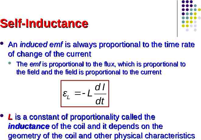
Self-Inductance An induced emf is always proportional to the time rate of change of the current The emf is proportional to the flux, which is proportional to the field and the field is proportional to the current dI εL L dt L is a constant of proportionality called the inductance of the coil and it depends on the geometry of the coil and other physical characteristics
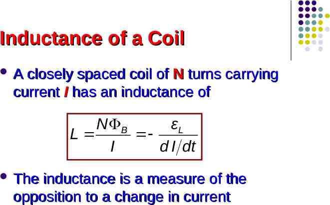
Inductance of a Coil A closely spaced coil of N turns carrying current I has an inductance of N B εL L I d I dt The inductance is a measure of the opposition to a change in current
Inductance Units The SI unit of inductance is the henry (H) V s 1H 1 A Named for Joseph Henry
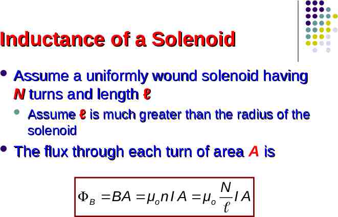
Inductance of a Solenoid Assume a uniformly wound solenoid having N turns and length ℓ Assume ℓ is much greater than the radius of the solenoid The flux through each turn of area A is N B BA μo n I A μo I A
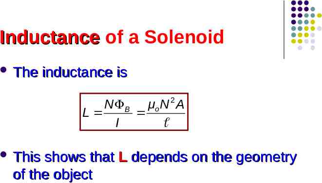
Inductance of a Solenoid The inductance is N B μo N 2 A L I This shows that L depends on the geometry of the object
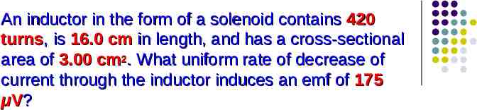
An inductor in the form of a solenoid contains 420 turns, is 16.0 cm in length, and has a cross-sectional area of 3.00 cm2. What uniform rate of decrease of current through the inductor induces an emf of 175 μV?
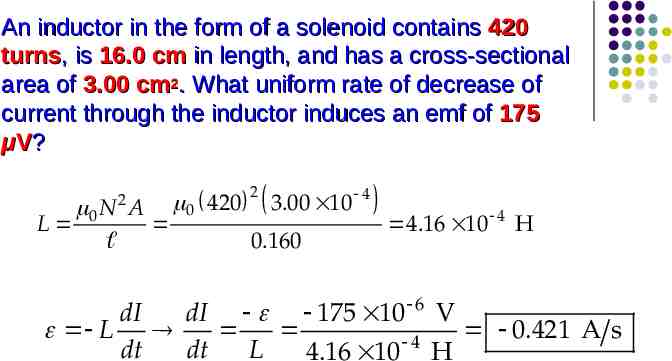
An inductor in the form of a solenoid contains 420 turns, is 16.0 cm in length, and has a cross-sectional area of 3.00 cm2. What uniform rate of decrease of current through the inductor induces an emf of 175 μV? 2 0 N A L 0 420 2 3.00 10 4 0.160 4.16 10 4 H dI dI 175 10 6 V L 0.421 A s 4 dt dt L 4.16 10 H
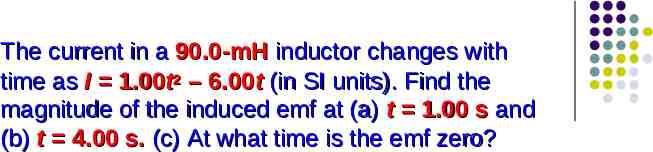
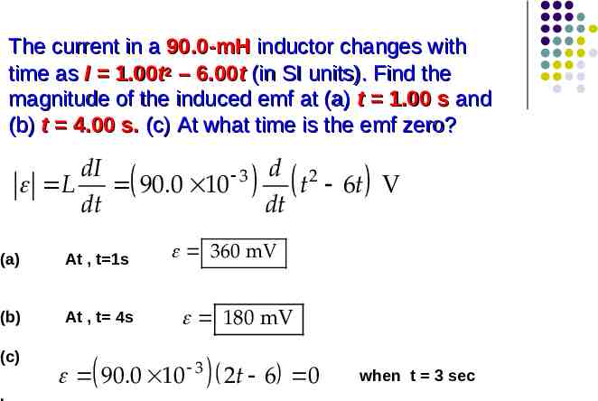
The current in a 90.0-mH inductor changes with time as I 1.00t2 – 6.00t (in SI units). Find the magnitude of the induced emf at (a) t 1.00 s and (b) t 4.00 s. (c) At what time is the emf zero?
The current in a 90.0-mH inductor changes with time as I 1.00t2 – 6.00t (in SI units). Find the magnitude of the induced emf at (a) t 1.00 s and (b) t 4.00 s. (c) At what time is the emf zero? dI 3 d 2 L 90.0 10 t 6t V dt dt (a) At , t 1s (b) At , t 4s (c) . 360 mV 180 mV 90.0 10 3 2t 6 0 when t 3 sec
RL Circuit, Introduction A circuit element that has a large selfinductance is called an inductor The circuit symbol is We assume the self-inductance of the rest of the circuit is negligible compared to the inductor However, even without a coil, a circuit will have some self-inductance
Effect of an Inductor in a Circuit The inductance results in a back emf Therefore, the inductor in a circuit opposes changes in current in that circuit The inductor attempts to keep the current the same way it was before the change occurred The inductor can cause the circuit to be “sluggish” as it reacts to changes in the voltage
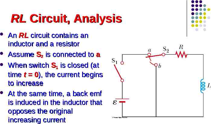
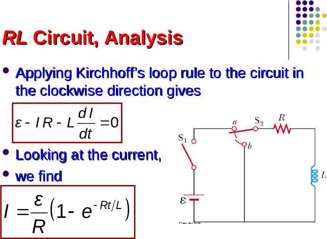
RL Circuit, Analysis An RL circuit contains an inductor and a resistor Assume S2 is connected to a When switch S1 is closed (at time t 0), the current begins to increase At the same time, a back emf is induced in the inductor that opposes the original increasing current
RL Circuit, Analysis Applying Kirchhoff’s loop rule to the circuit in the clockwise direction gives dI ε IR L 0 dt Looking at the current, we find ε Rt L I 1 e R
RL Circuit, Analysis The inductor affects the current exponentially The current does not instantly increase to its final equilibrium value If there is no inductor, the exponential term goes to zero and the current would instantaneously reach its maximum value as expected
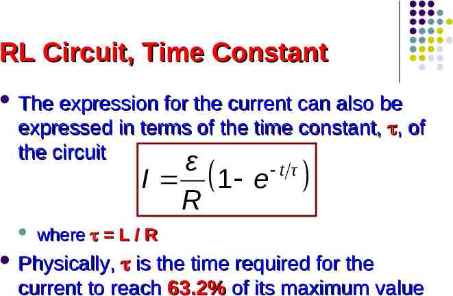
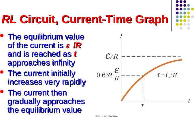
RL Circuit, Time Constant The expression for the current can also be expressed in terms of the time constant, , of the circuit ε t τ I 1 e R where L / R Physically, is the time required for the current to reach 63.2% of its maximum value
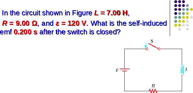
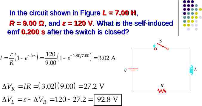
In the circuit shown in Figure L 7.00 H, R 9.00 Ω, and ε 120 V. What is the self-induced emf 0.200 s after the switch is closed?
In the circuit shown in Figure L 7.00 H, R 9.00 Ω, and ε 120 V. What is the self-induced emf 0.200 s after the switch is closed? 120 t I 1 e 1 e 1.80 7.00 3.02 A R 9.00 VR IR 3.02 9.00 27.2 V VL VR 120 27.2 92.8 V
RL Circuit, Current-Time Graph The equilibrium value of the current is /R and is reached as t approaches infinity The current initially increases very rapidly The current then gradually approaches the equilibrium value
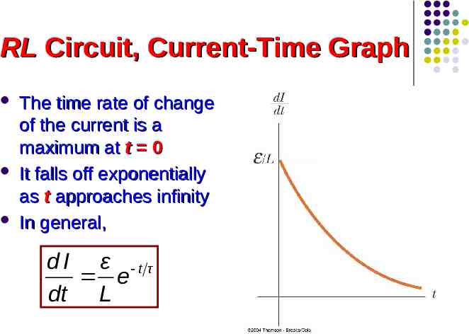
RL Circuit, Current-Time Graph The time rate of change of the current is a maximum at t 0 It falls off exponentially as t approaches infinity In general, dI ε t τ e dt L
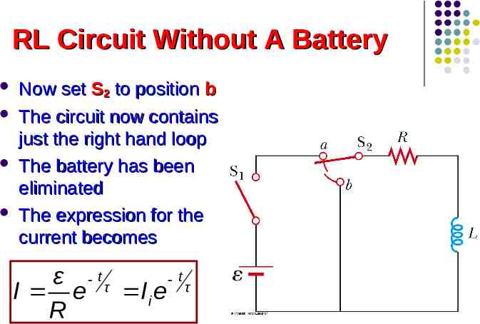
RL Circuit Without A Battery Now set S2 to position b The circuit now contains just the right hand loop The battery has been eliminated The expression for the current becomes ε tτ t I e Ii e τ R
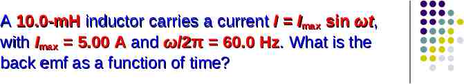
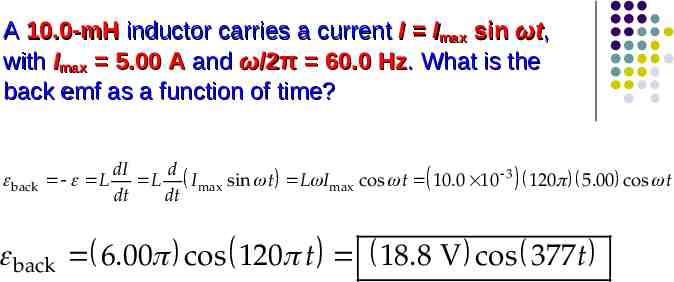
A 10.0-mH inductor carries a current I Imax sin ωt, with Imax 5.00 A and ω/2π 60.0 Hz. What is the back emf as a function of time?
A 10.0-mH inductor carries a current I Imax sin ωt, with Imax 5.00 A and ω/2π 60.0 Hz. What is the back emf as a function of time? back L dI d L Imax sin t L Imax cos t 10.0 10 3 120 5.00 cos t dt dt back 6.00 cos 120 t 18.8 V cos 377 t
Energy in a Magnetic Field In a circuit with an inductor, the battery must supply more energy than in a circuit without an inductor Part of the energy supplied by the battery appears as internal energy in the resistor The remaining energy is stored in the magnetic field of the inductor
Energy in a Magnetic Field Looking at this energy (in terms of rate) dI I ε I R LI dt 2 I is the rate at which energy is being supplied by the battery I2R is the rate at which the energy is being delivered to the resistor Therefore, LI (dI/dt) must be the rate at which the energy is being stored in the inductor
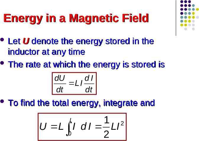
Energy in a Magnetic Field Let U denote the energy stored in the inductor at any time The rate at which the energy is stored is dU dI L I dt dt To find the total energy, integrate and 1 2 U L I d I LI 0 2 I
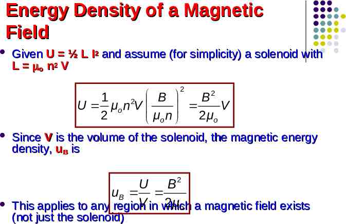
Energy Density of a Magnetic Field Given U ½ L I2 and assume (for simplicity) a solenoid with L o n 2 V 2 2 1 B B U μo n 2V V 2 2 μo μo n Since V is the volume of the solenoid, the magnetic energy density, uB is U B2 uB V in which 2 μo a magnetic field exists This applies to any region (not just the solenoid)
Energy Storage Summary A resistor, inductor and capacitor all store energy through different mechanisms Charged capacitor Inductor Stores energy as electric potential energy When it carries a current, stores energy as magnetic potential energy Resistor Energy delivered is transformed into internal energy
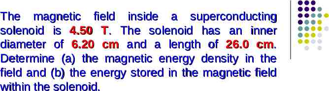
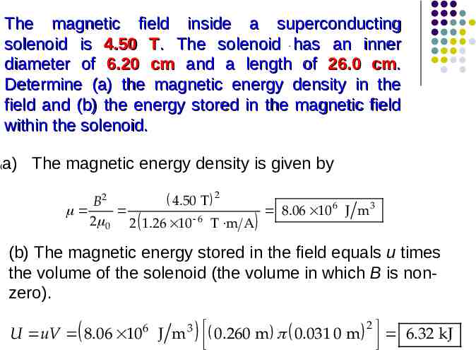
The magnetic field inside a superconducting solenoid is 4.50 T. The solenoid has an inner diameter of 6.20 cm and a length of 26.0 cm. Determine (a) the magnetic energy density in the field and (b) the energy stored in the magnetic field within the solenoid.
The magnetic field inside a superconducting solenoid is 4.50 T. The solenoid . has an inner diameter of 6.20 cm and a length of 26.0 cm. Determine (a) the magnetic energy density in the field and (b) the energy stored in the magnetic field within the solenoid. ( a) The magnetic energy density is given by 2 4.50 T B2 6 3 8.06 10 J m 2 0 2 1.26 10 6 T m A (b) The magnetic energy stored in the field equals u times the volume of the solenoid (the volume in which B is nonzero). 6 U uV 8.06 10 J m 3 0.260 m 0.031 0 m 2 6.32 kJ
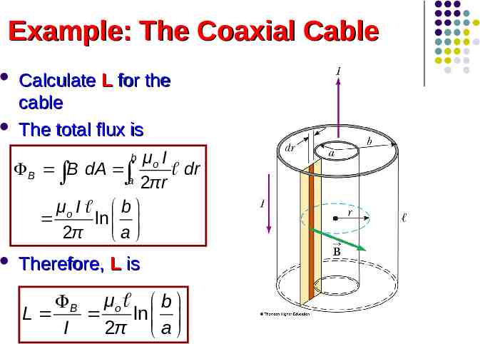
Example: The Coaxial Cable Calculate L for the cable The total flux is b μ I B B dA o dr a 2πr μo I b ln 2π a Therefore, L is B μo b L ln I 2π a
Mutual Inductance The magnetic flux through the area enclosed by a circuit often varies with time because of time-varying currents in nearby circuits This process is known as mutual induction because it depends on the interaction of two circuits
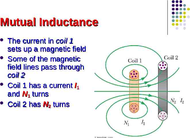
Mutual Inductance The current in coil 1 sets up a magnetic field Some of the magnetic field lines pass through coil 2 Coil 1 has a current I1 and N1 turns Coil 2 has N2 turns
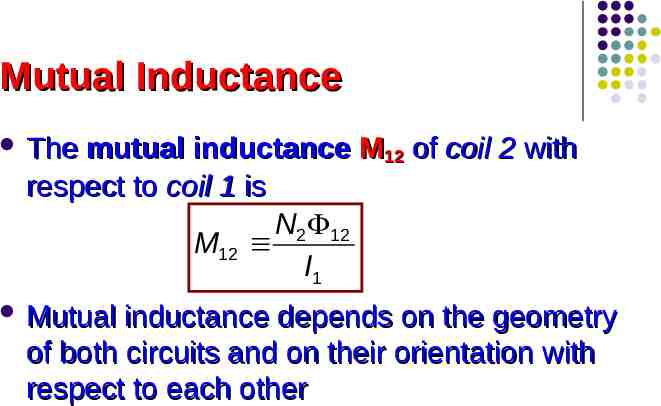
Mutual Inductance The mutual inductance M12 of coil 2 with respect to coil 1 is N2 12 M12 I1 Mutual inductance depends on the geometry of both circuits and on their orientation with respect to each other
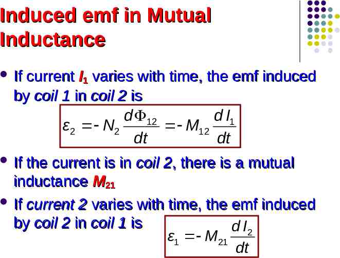
Induced emf in Mutual Inductance If current I1 varies with time, the emf induced by coil 1 in coil 2 is d 12 d I1 ε2 N2 M12 dt dt If the current is in coil 2, there is a mutual inductance M21 If current 2 varies with time, the emf induced by coil 2 in coil 1 is d I2 ε1 M21 dt
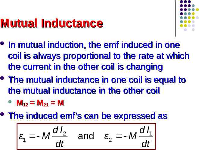
Mutual Inductance In mutual induction, the emf induced in one coil is always proportional to the rate at which the current in the other coil is changing The mutual inductance in one coil is equal to the mutual inductance in the other coil M12 M21 M The induced emf’s can be expressed as d I2 ε1 M dt and d I1 ε2 M dt
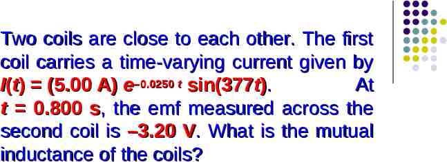
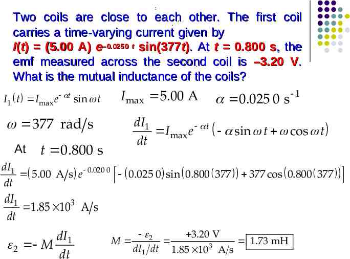
Two coils are close to each other. The first coil carries a time-varying current given by I(t) (5.00 A) e–0.0250 t sin(377t). At t 0.800 s, the emf measured across the second coil is –3.20 V. What is the mutual inductance of the coils?
: Two coils are close to each other. The first coil , . carries a time-varying current given by I(t) (5.00 A) e–0.0250 t sin(377t). At t 0.800 s, the emf measured across the second coil is –3.20 V. . What is the mutual inductance of the coils? I1 t I max e t sin t I max 5.00 A dI1 I max e t sin t cos t dt 377 rad s At 0.025 0 s 1 t 0.800 s dI1 5.00 A s e 0.020 0 0.025 0 sin 0.800 377 377 cos 0.800 377 dt dI1 1.85 10 3 A s dt dI1 2 M dt M 2 3.20 V 1.73 mH 3 dI1 dt 1.85 10 A s
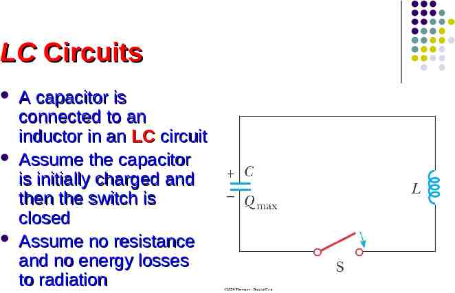
LC Circuits A capacitor is connected to an inductor in an LC circuit Assume the capacitor is initially charged and then the switch is closed Assume no resistance and no energy losses to radiation
Oscillations in an LC Circuit Under the previous conditions, the current in the circuit and the charge on the capacitor oscillate between maximum positive and negative values With zero resistance, no energy is transformed into internal energy Ideally, the oscillations in the circuit persist indefinitely The idealizations are no resistance and no radiation
Oscillations in an LC Circuit The capacitor is fully charged The energy U in the circuit is stored in the electric field of the capacitor The energy is equal to Q2max / 2C The current in the circuit is zero No energy is stored in the inductor The switch is closed
Oscillations in an LC Circuit The current is equal to the rate at which the charge changes on the capacitor As the capacitor discharges, the energy stored in the electric field decreases Since there is now a current, some energy is stored in the magnetic field of the inductor Energy is transferred from the electric field to the magnetic field
Oscillations in an LC Circuit Eventually, the capacitor becomes fully discharged It stores no energy All of the energy is stored in the magnetic field of the inductor The current reaches its maximum value The current now decreases in magnitude, recharging the capacitor with its plates having opposite their initial polarity
Oscillations in an LC Circuit The capacitor becomes fully charged and the cycle repeats The energy continues to oscillate between the inductor and the capacitor The total energy stored in the LC circuit remains constant in time and equals Q2 1 2 U UC UL LI 2C 2
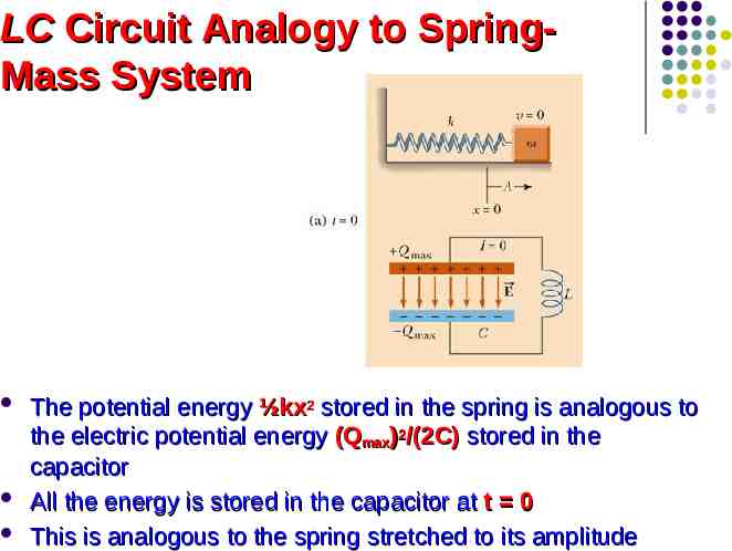
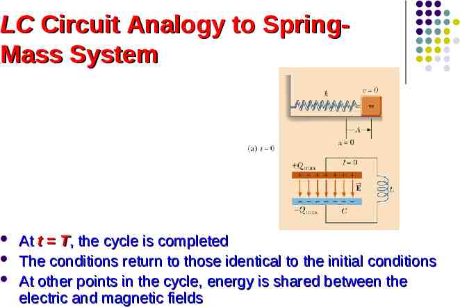
LC Circuit Analogy to SpringMass System The potential energy ½kx2 stored in the spring is analogous to the electric potential energy (Qmax)2/(2C) stored in the capacitor All the energy is stored in the capacitor at t 0 This is analogous to the spring stretched to its amplitude
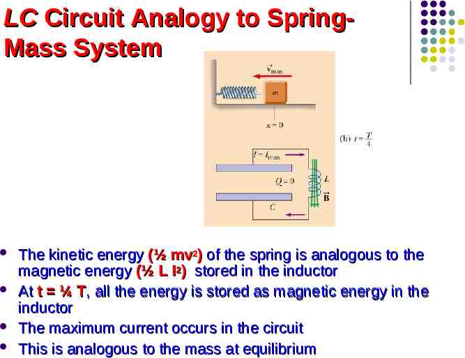
LC Circuit Analogy to SpringMass System The kinetic energy (½ mv2) of the spring is analogous to the magnetic energy (½ L I2) stored in the inductor At t ¼ T, all the energy is stored as magnetic energy in the inductor The maximum current occurs in the circuit This is analogous to the mass at equilibrium
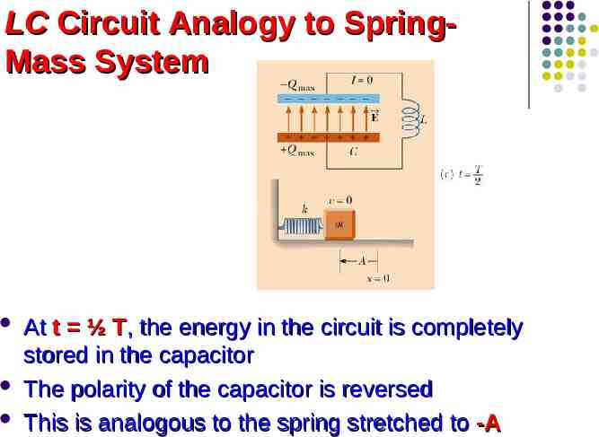
LC Circuit Analogy to SpringMass System At t ½ T, the energy in the circuit is completely stored in the capacitor The polarity of the capacitor is reversed This is analogous to the spring stretched to -A
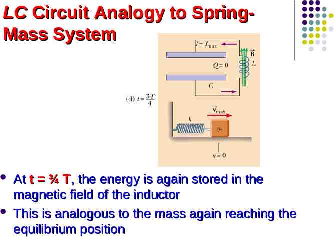
LC Circuit Analogy to SpringMass System At t ¾ T, the energy is again stored in the magnetic field of the inductor This is analogous to the mass again reaching the equilibrium position
LC Circuit Analogy to SpringMass System At t T, the cycle is completed The conditions return to those identical to the initial conditions At other points in the cycle, energy is shared between the electric and magnetic fields
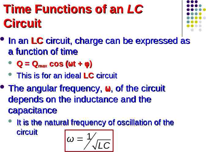
Time Functions of an LC Circuit In an LC circuit, charge can be expressed as a function of time Q Qmax cos (ωt φ) This is for an ideal LC circuit angular frequency, ω, of the circuit depends on the inductance and the capacitance The It is the natural frequency of oscillation of the circuit ω 1 LC
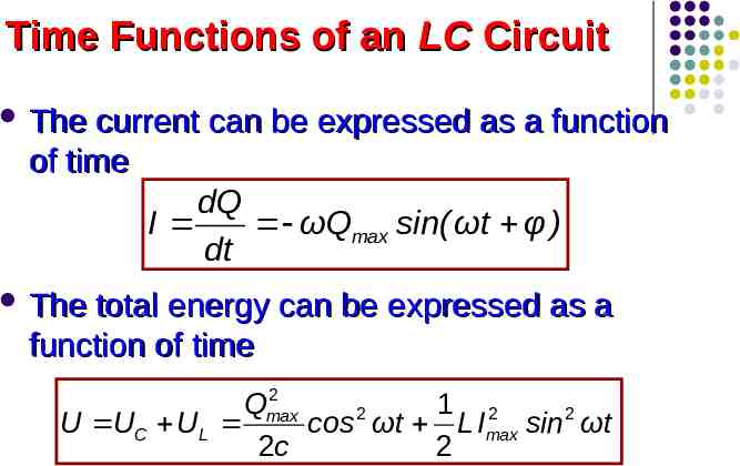
Time Functions of an LC Circuit The current can be expressed as a function of time dQ I ωQmax sin(ωt φ ) dt The total energy can be expressed as a function of time 2 Qmax 1 2 2 U UC UL cos ωt LImax sin 2 ωt 2c 2
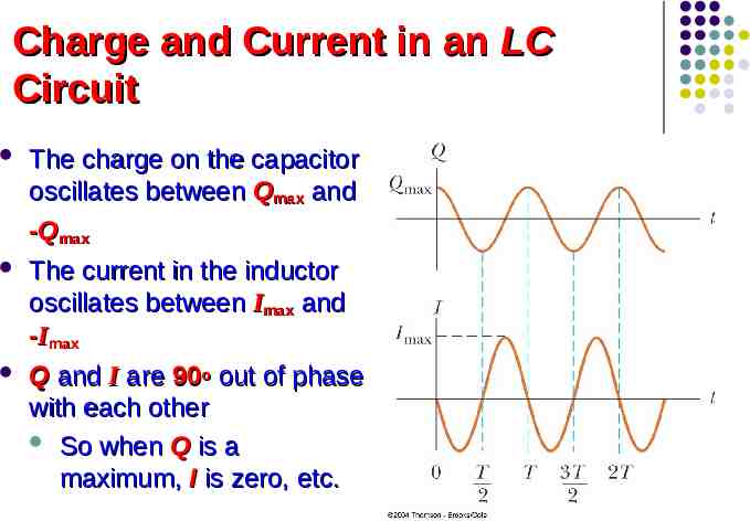
Charge and Current in an LC Circuit The charge on the capacitor oscillates between Qmax and -Qmax The current in the inductor oscillates between Imax and -Imax Q and I are 90o out of phase with each other So when Q is a maximum, I is zero, etc.
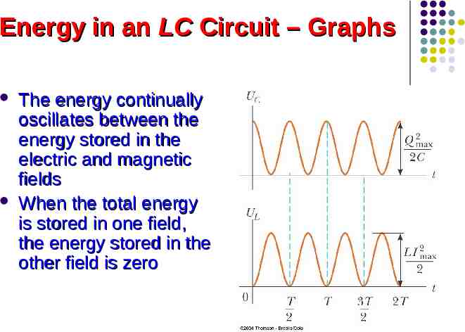
Energy in an LC Circuit – Graphs The energy continually oscillates between the energy stored in the electric and magnetic fields When the total energy is stored in one field, the energy stored in the other field is zero
Notes About Real LC Circuits In actual circuits, there is always some resistance Therefore, there is some energy transformed to internal energy Radiation is also inevitable in this type of circuit The total energy in the circuit continuously decreases as a result of these processes
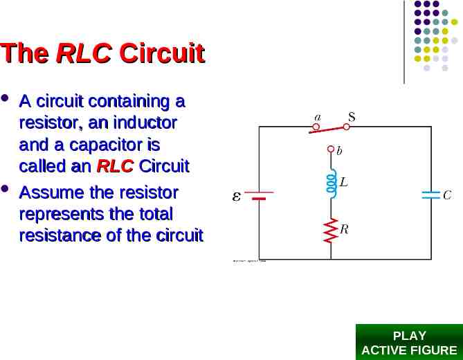
The RLC Circuit A circuit containing a resistor, an inductor and a capacitor is called an RLC Circuit Assume the resistor represents the total resistance of the circuit PLAY ACTIVE FIGURE
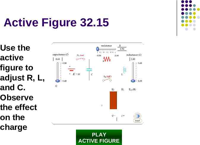
Active Figure 32.15 Use the active figure to adjust R, L, and C. Observe the effect on the charge PLAY ACTIVE FIGURE
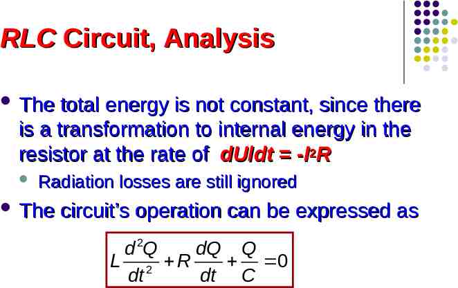
RLC Circuit, Analysis The total energy is not constant, since there is a transformation to internal energy in the resistor at the rate of dU/dt -I2R Radiation losses are still ignored The circuit’s operation can be expressed as d 2Q dQ Q L 2 R 0 dt dt C
RLC Circuit Compared to Damped Oscillators The RLC circuit is analogous to a damped harmonic oscillator When R 0 The circuit reduces to an LC circuit and is equivalent to no damping in a mechanical oscillator
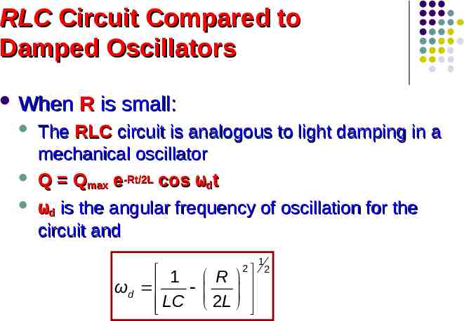
RLC Circuit Compared to Damped Oscillators When R is small: The RLC circuit is analogous to light damping in a mechanical oscillator Q Qmax e-Rt/2L cos ωdt ωd is the angular frequency of oscillation for the circuit and 1 R ωd LC 2 L 2 1 2
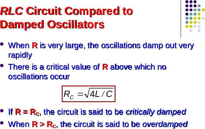
RLC Circuit Compared to Damped Oscillators When R is very large, the oscillations damp out very rapidly There is a critical value of R above which no oscillations occur RC 4L / C If R RC, the circuit is said to be critically damped When R RC, the circuit is said to be overdamped
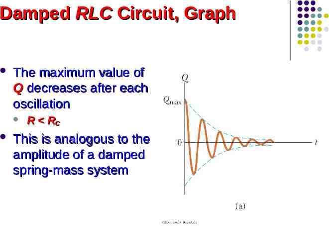
Damped RLC Circuit, Graph The maximum value of Q decreases after each oscillation R RC This is analogous to the amplitude of a damped spring-mass system
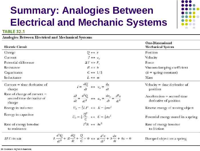
Summary: Analogies Between Electrical and Mechanic Systems