Unit-1 Indicating & Recording Instruments 1


81 Slides3.50 MB
Unit-1 Indicating & Recording Instruments 1
Introduction to Recorders It is often necessary to have a permanent record of a phenomenon being investigated, e.g., in industrial & research processes, it is required to monitor continuously the condition, state, or value of the process variables such as flow, pressure, temperature, current, & voltage etc. A recorder, thus, records electrical/non-electrical quantities as a function of time This record may be written/printed and later on can be examined & analyzed to obtain a better understanding and control of the process Currents/voltages can be recorded directly while non-electrical quantities are recorded indirectly by first converting them to equivalent currents/voltages with the help of sensors or transducers 2
Classification of Recorders Depending on how the data acquired is recorded? The recorders are classified as follow: (A) Analog Recorders: When we are dealing with a wholly analog system Broadly, analog recorders are classified into: (1) Graphic Recorders (2) Oscillographic Recorders (3) Magnetic-Tape Recorders (B) Digital Recorder: For the system whose output is in digital form 3
(1) Graphic Recorders Generally, graphic recorders are devices which display & store pen-and-ink record of the history of some physical event on a chart Basic Elements of Graphic Recorder: Chart for displaying & storing the recorded information A stylus or pen moving in proper relationship to paper/chart A suitable means of Interconnection or Interface to couple the stylus to the source of information Graphic recorders may be classified into: (a) Strip chart recorders (b) X-Y recorders 4
Strip Chart Recorders 5
Strip Chart Recorders (-contd.) (i) (ii) (iii) (iv) A strip chart recorder records one or more variables w.r.t. time It is an X-t recorder, which consists of: A long roll of graph paper A system for driving the paper at some selected speed (usually 1-100 mm/s) by means of speed selector switch A stylus, moving horizontally in proportion to the quantity being recorded A stylus driving mechanism which moves the stylus in nearly exact replica of the quantity being recorded The mechanisms used for marking the marks on the paper are as follow: Marking with ink filled stylus Marking with heated stylus Chopper Bar Electronic Stylus Electrostatic Stylus Optical Marking Method 6
Marking with Ink Filled Stylus The stylus is filled with ink by gravity or capillary actions The pointer supports an ink reservoir & a pen, or contain a capillary connection between the pen & pen reservoir This method is most commonly employed because ordinary paper can be used and thus the cost is low Other advantages: Operation over a very wide range of recording speeds is possible Little friction between the stylus tip & the paper Disadvantages: Ink splatters at high speeds, batches at low speeds, & clogs when the stylus is at rest The frequency limit of recorders incorporating this method of writing is only few Hz 7
Marking with Heated Stylus Some recorders use a heated stylus which writes on a special paper (a thin white wax like coating on a black paper) This overcomes the difficulties encountered in ink writing system Quite reliable & offers high contrast traces Sophisticated records, having a frequency response upto 40 Hz, are available Since the paper is a special one, the cost is high This method can’t be used for recording certain processes which produce heat & indirectly affect the recordings 8
Chopper Bar If a chart made of a pressure sensitive paper is used then a V-shaped pointer is passed under a chopper bar which presses the pen into the paper once per sec (or any other selected interval) thus marking a series of marks on the paper As this system is not purely continuous, thus it is suitable for recording some slowly varying quantities (e.g. having a variation of 1 cycle per hour) 9
Electronic Stylus This method uses a paper with a special coating which is sensitive to current When the current is conducted from the stylus to the paper, a trace appears on the paper The electronic stylus marking method has a wide range of marking speeds, low stylus friction, & a long stylus life 10
Electrostatic Stylus This method uses a stylus which produces a high voltage discharge, thereby, producing a permanent trace on an electrosensitive paper This arrangement has been incorporated in a recorder having a 50 mm wide chart with 9 voltage ranges (10 mV/mm – 5 V/mm), 8 chart speeds (300 – 600 mm/s), & a frequency response of 60 Hz at maximum amplification of 1 dB 11
Optical Marking Method This method uses a beam of light to write on a photosensitive paper This method allows higher frequencies to be recorded and permits a relatively large chart speed with good resolution Disadvantages: Paper cost is very high Photographic paper must be developed before a record is available Not suitable for processes where instantaneous monitoring is to be done 12
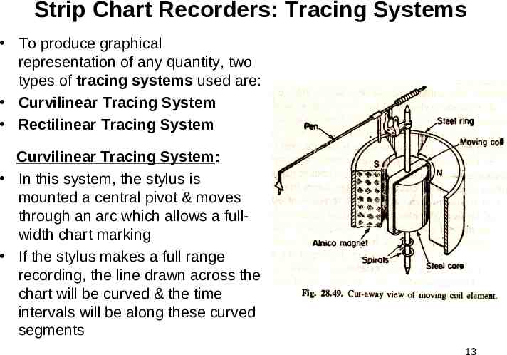
Strip Chart Recorders: Tracing Systems To produce graphical representation of any quantity, two types of tracing systems used are: Curvilinear Tracing System Rectilinear Tracing System Curvilinear Tracing System: In this system, the stylus is mounted a central pivot & moves through an arc which allows a fullwidth chart marking If the stylus makes a full range recording, the line drawn across the chart will be curved & the time intervals will be along these curved segments 13
Curvilinear Tracing System This type of system is used on many recorders with PMMC galvanometers actuating the stylus filled with ink as shown in fig. (28.50) The disadvantage of this method of tracing is the charts are difficult to analyze because of curved time base lines 14
Rectilinear Tracing System Fig. (28.51) shows rectilinear system of tracing This system produces a straight line across the width of the chart Here, the stylus is actuated by a drive cord over pulleys to produce forward/reverse motion as determined by drive mechanism The stylus may be actuated by a self balancing potentiometer system, a photoelectric deflection system, a photoelectric potentiometer system, or a bridge balance system This is usually used with thermal or electric writing 15
Types of Strip Chart Recorders There are two different types of strip chart recorders: Galvanometer Type Null Type Galvanometer Type Strip Chart Recorder: The deflection in this recorder is produced by a galvanometer (d’Arsonval) which produces a torque on account of a current passing through its coil The current is proportional to the quantity being measured When the pointer comes to rest because of controlling torque exerted by springs, the stylus also comes to rest and thus the value of the quantity is recorded This type of recorder is not useful for recording fast variations in current/voltage/power and only records the average values The range of operation is from few mA/mV to several mA/mV 16
Types of Strip Chart Recorders (-contd.) These moving galvanometer type recorder is comparatively inexpensive instrument having a narrow bandwidth of 0-10 Hz and a sensitivity of 0.4 mV/mm For measurement of smaller voltage, linear amplifiers are used Null Type Strip Chart Recorder: Many recorders operate on the principle whereby a change in its input upsets the balance of the measuring circuit of the recorder As a result of this unbalance, an error signal is produced that operates some device which restores balance or brings the system to null condition The amount of movement of this balance restoring device is an indication of the magnitude of the error signal and the direction of the movement is an indication of the direction of the quantity being measured has deviated from normal The signal from the transducer/sensor may take any of the forms: voltage 17 (ac or dc), current (ac or dc), resistance, inductance, or capacitance
Null Type Recorders There are a number of null type strip chart recorders: (i) Potentiometric Recorders (ii)Bridge Recorders (iii)LVDT (Linear Variable Differential Transformer) Recorder Note: The principle of operation for all these recorders is same, i.e., to obtain null condition 18
Potentiometric Recorders The basic disadvantage of a galvanometer type of recorder is that it has a low input impedance A simple method of overcoming the input impedance problem is to use an amplifier between the input terminals & the display/indicating instrument However, this technique, while producing a high input impedance (to reduce loading effect) & improved sensitivity (4V/mm), results in an instrument having low accuracy The accuracy can be improved if the input signal is compared with a reference voltage by using a potentiometer circuit The error signal (difference between the input signal & the potentiometer voltage) is amplified and is used to energize the field coil of a dc motor, which moves over the potentiometer in the appropriate direction to reduce the magnitude of the error signal and to obtain balance 19
Potentiometric Recorders (-contd.) The wiper comes to rest when the unknown signal voltage is balanced against the voltage of the potentiometer The chart drive for most potentiometer recorders is obtained from a motor synchronized to power line frequency Different speeds may be obtained by using a gear train that uses different gear ratios The most common application of the potentiometric recorders is for recording & control of process temperature 20
Single Point & Multipoint Recorders Most of the graphic records show variation of one variable (e.g. temperature) with time The instruments that record changes of only one measured variable w.r.t. time are called single-point recorders and the trace of such instruments is usually in the form of single continuous curve However, in process industry, it becomes necessary to record simultaneously variables like pressure, temperature, flow rate, liquid level etc. This feature may be performed either by having several pens (maximum four) which overlap each other & record the inputs simultaneously, or by replacing the pen by print wheel geared to a selector switch so that when a particular input is connected to the potentiometer balance circuit, a point plus its identifying character is printed on the chart This form of recorder is called a multi-point recorder and may have as many as 24 inputs, with traces displayed in 6 colors 21
X-Y Recorders 22
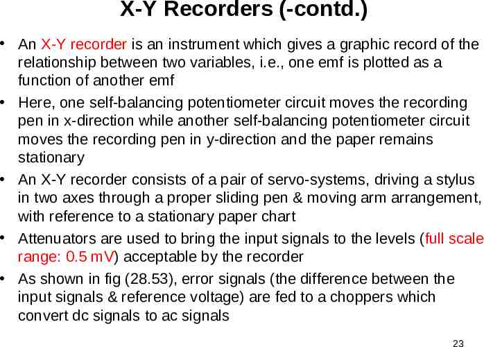
X-Y Recorders (-contd.) An X-Y recorder is an instrument which gives a graphic record of the relationship between two variables, i.e., one emf is plotted as a function of another emf Here, one self-balancing potentiometer circuit moves the recording pen in x-direction while another self-balancing potentiometer circuit moves the recording pen in y-direction and the paper remains stationary An X-Y recorder consists of a pair of servo-systems, driving a stylus in two axes through a proper sliding pen & moving arm arrangement, with reference to a stationary paper chart Attenuators are used to bring the input signals to the levels (full scale range: 0.5 mV) acceptable by the recorder As shown in fig (28.53), error signals (the difference between the input signals & reference voltage) are fed to a choppers which convert dc signals to ac signals 23
X-Y Recorders (-contd.) The signals are then amplified in order to actuate servomotors which are used to balance the system & hold it in balance as the value of the quantity being recorded changes Thus, we get a record of one variable w.r.t. another In some X-Y recorders, one self-balancing potentiometer controls the position of the rolls (i.e. the paper) while another self-balancing potentiometer controls the position of the recording pen An X-Y recorder may have a sensitivity of 10 µV/mm, a slewing speed of 1.5 m/s, a frequency response about 6 Hz for both axes, chart size of 250 x 180 mm, and accuracy of about 0.3% 24
X-Y Recorders (-contd.) Uses: (i) Speed-torque characteristics of motors (ii) Plotting of characteristics of zener diodes, rectifiers, transistors (iii) Regulation curve (output versus input voltage) of power supplies (iv) Electrical characteristics of materials such as resistance versus temperature (v) Plotting stress versus strain curves, hysteresis curves etc. 25
Oscillographic Recorders Ultraviolet Recorders: 26
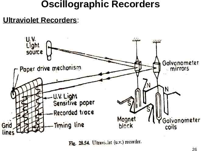
Ultraviolet Recorders (-contd.) These are basically electromechanical oscillographic recorders consist of a number of galvanometer (moving coil) elements mounted in a single magnet block as shown in figure The galvanometer uses a source of ultraviolet (u.v.) light in place of white light and a paper sensitive to u.v. light is used for producing a trace for recording The u.v. light is projected on the paper with the help of mirrors attached to the moving coils (pencil galvanometers) As shown in figure, when a current is passed through the galvanometer coil, it deflects under the influence of magnetic field of permanent magnet The u.v. light falling on the mirrors is reflected & projected on the u.v. light sensitive paper through a lens & mirror system The paper is driven past the moving light spot & thus a trace of variation of current w.r.t. time is produced 27
Ultraviolet Recorders (-contd.) The u.v. sensitive paper may be processed & photo-developed, permanized or photocopied The u.v. recorders are multichannel & have as many as 25 channels Since, each channel may produce a 10 cm wide p-p trace on a 30 cm wide paper, there will be considerable overlapping of traces produced by different channels Therefore, it is essential to provide an identification mark for each trace so as to avoid confusion A simplified identification process is to interrupt each trace momentarily in turn & to coincide this interruption with a character marked on the side of record by passing u.v. light through cutouts of the character 28
Ultraviolet Recorders (-contd.) The u.v. recorder may be used for dc & ac signals having a fundamental frequency upto 400 to 500 Hz The frequency range depends on the recorder being used and paper driving speeds The recording of high frequency inputs is possible if recorders with high paper speeds of about 10 m/s are available These recorders are also used for recording the magnitude of low frequency signals which can’t be measured with analog (pointer) type instruments Applications: Typical applications of u.v. recorders are in recording: (i) output of transducers, (ii) control system performance, & (iii) regulation transients of generators 29
Magnetic Tape Recorders Take up Real 30
Magnetic Tape Recorders (-contd.) It is frequently desirable & in many cases necessary to record data in such a way that they can be retrieved/reproduced in electrical form again The most common & useful way of achieving this is through the use of magnetic tape recording Generally, the magnetic tape recorders are used at high frequency A magnetic tape recorder consists of the following basic components: (i) Recording Head, (ii) Magnetic Tape, (iii) Reproducing Head, (iv) Tape Transport Mechanism, & (v) Conditioning Devices 31
Magnetic Tape Recorders (-contd.) (i) Recording Head: This device responds to an electrical signal in such a manner that a magnetic pattern is created in a magnetizable medium A fine air gap of length 5-15 µm is shunted by passing the magnetic tape A current in the coil causes a flux of the same shape to bridge the air gap & hence to pass through the magnetic tape, thereby, magnetizing the iron oxide (Fe2O3) particles as they pass the air gap The state of magnetization of the oxide as it leaves the air gap is retained, thus the actual recording takes place at the trailing edge of the gap Any signal recorded on the tape appears as a magnetic pattern dispersed in space along the tape similar to the original coil current variation with time 32
Magnetic Tape Recorders (-contd.) (ii) Magnetic Tape: Magnetic tape (12.7 mm wide & 25.4 µm thick) is composed of a coating of fine magnetic iron oxide particles (Fe2O3) on a plastic ribbon The magnetic particles conform to the magnetic pattern induced in them & retain it (iii) Reproducing Head: The reproducing head detects the magnetic pattern stored in them & converts it back to original electrical signal Reproducing is similar in appearance to that of a recording head (iv) Tape Transport Mechanism: This mechanism moves the tape along the recording of the reproducing heads at constant speed 33
Magnetic Tape Recorders (-contd.) The tape mechanism must be capable of handling the tape during various modes of operation without straining, distortion, or wearing out the tape This requires that the mechanism must use arrangements to guide the tape past the magnetic heads with great precision, maintain proper tension, & obtain sufficient tape to magnetic head contact Arrangement for fast winding & reversing are also provided A capstan & pinch roller are used to drive the tape (v) Conditioning Devices: These devices consist of amplifiers & filters required for modifying the signal to a format that can be properly recorded on a tape 34
Magnetic Tape Recorders (-contd.) Working Principle: When a magnetic tape is passed through a recording head, any signal recorded on the tape appears as magnetic pattern dispersed in space along the tape, similar to the original coil current variation with time The same tape when passed through reproduce/playback head produces variations in the reluctance of the winding, thereby, inducing a voltage in the winding dependent upon the direction of magnetization & its magnitude on the magnetic tape 35
Magnetic Tape Recorders (-contd.) The induced voltage is proportional to rate of change of flux linkages Therefore, the emf induced in the winding of reproducing head is proportional to rate of change of the level of magnetization on the rate , where N is number of turns of the winding d i . e ., e N rep put on the reproduce head dt Since, the voltage in the reproduce head is proportional to d, the reproduce head acts as a differentiator dt For example, let the original signal be A sin(ωt) The current in the record head winding & the flux produced will be proportional to this voltage, i.e., Ф K1 A sin(ωt) (1) where K1 is constant Assuming that the tape retains this flux pattern & regenerates it in the reproduce head, the voltage induced in the reproduce head winding is . (2) e rep KN d K 2 NA cos( t ) dt 36
Magnetic Tape Recorders (-contd.) Thus the output signal from the reproduce head is derivative of the input signal The magnitude of the output signal is not only proportional to the flux recorded on the tape but also the frequency of the recorded signal Since, the recording is done at constant current level for all frequencies, and therefore, in order to have an overall flat frequency response (i.e., a high fidelity), the reproduce head characteristics and the characteristics of the amplifier connected in the reproduce head circuit must be complementary (i.e., the amplitude must have a response of 6dB/octave as shown in figure) This process of compensation is known as “equalization” 37
Magnetic Tape Recorders (-contd.) 1. 2. 3. 4. 5. 6. Advantages: Magnetic tape recorders have a wide frequency range from dc to several MHz They have a wide dynamic range which exceeds 50dB, this permits the linear recording from full scale signal level to approximately 0.3% of full scale They have a low distortion The magnitude of the electrical input signal is stored in magnetic memory and this signal can be reproduced whenever desired The recorded signal is immediately available with no time loss in processing, the recorded signal can be reproduced (played back) as many times as desired without loss of signal When the information has been processed, the tape can be erased & reused to record a new set of data 38
Magnetic Tape Recorders (-contd.) 7. Magnetic tape recording permits multi-channel recording, i.e., a tape facilitates the continuous record of a number of signals to be made simultaneously, which is a great advantage especially when recording transient & “once only” signals 8. The use of magnetic tape recorders provides a convenient method of changing the time base, i.e., the data may be recorded at very fast speeds (1.52 or 3.05 m/s) and played back at speeds (2.38 or 4.76 cm/s) slow enough to be recorded with low frequency recorders like graphic recorders 39
Digital Tape Recorders Digital magnetic tapes are often used as storage devices in digital processing applications Digital tape units are of two types: (a)Incremental digital tape recorders (b)Synchronous Digital Tape Recorders (a)Incremental Digital Tape Recorders: They are commanded to step ahead (increment) for each digital character to be recorded Input data may be at a relatively slow, or even discontinuous rate In this way, each character is equally & precisely spaced along the tape 40
Digital Tape Recorders (-contd.) (b) Synchronous Digital Tape Recorders: In these, the tape moves at a constant speed (about 75 cm/s) while a large number of data characters are recorded The data inputs are at precise rates upto 10’s of thousand characters/second The tape is brought to speed, recording takes place, and tape is brought to a fast stop In this way, a block of characters (a record) is written with each character spaced equally along the tape Blocks of data are usually separated from each other by an erased area on the tape called the record gap The synchronous tape unit starts & stops the tape for each block of data to be recorded 41
Digital Tape Recorders (-contd.) Digital Recording Method: In the above two methods, the characters are represented on magnetic tape by the coded combination of symbols (bits) 0 & 1 by the IBM-NRZ format This format uses the change in flux direction on the tape to indicate symbol 1 & no change in flux direction to indicate symbol 0 42
Digital Tape Recorders (-contd.) In digital data recording, a recording field of sufficient amplitude to produce magnetic saturation through the complete tape layer thickness is reversed to record 1 & kept constant to record 0 Reproduction of this recording is achieved by using a timing signal obtained from a separate clock track corresponding to the time when a ‘1’ or ‘0’ symbols are recorded In practice, larger fields are usually employed to ensure more reliable recordings on a coated thicker tape & also to minimize the effect of dropouts (due to some random surface inhomogenities in tape coatings because of dirt or poor manufacture, some portions of the tape may not be perfectly recorded, which is called dropout) As a check on dropout errors, most tape systems include a parity check 43
Digital Tape Recorders (-contd.) Advantages of Digital DataTape Recording: High accuracy Insensitivity to tape speed Use of simple conditioning equipment The information is fed directly to a digital computer for processing & control Disadvantages of Digital DataTape Recording: Poor tape economy The information from transducers is in analog form, hence an ADC is required A high quality tape & tape transport mechanism are required 44
Digital Display Devices Display devices provide a visual display of numbers, letters, & symbols in response to electrical input, and serve as constituents of an electronic display system The basic element in a digital display device is the display for a single character because a multiple character display is nothing but a group of single character displays Classification of Displays: In general, the displays are classified in a number of ways: 1. According to methods conversion of electrical data into visible light: (i) Active displays(Light Emitters)– CRTs, LEDs, Gas Discharge Plasma, etc. (ii) Passive Displays (Light Controllers) – LCDs 2. According to the Applications: (i) Analog Displays – Bar-graphic displays (CRT) (ii) Digital Displays – Nixies tubes, Alphanumeric, LEDs 45
Digital Display Devices (-contd.) 3. According to display size & physical dimensions: (i) Symbolic Displays – Alphanumeric, Nixie tubes, etc. (ii) Console Displays – CRTs, LEDs, etc. (ii) Large Screen Display – Enlarged Projection Systems 4. According to the display format: (i) Direct View Type (Flat Panel Planar) – Segmental, Dotmatrix, CRTs (ii) Stacked Electrode (Non-planar Type) – Nixie Tubes 5. In Terms of Resolution & Legibility of Characters (i) Simple Single Indicator (ii) Multi-element Displays 46
Segmental Displays The segmental displays may be either 7 or 14 segmental ones depending upon whether numeric or alphanumeric displays are required (i) Seven Segmental Display: This is used for numeric display, and consists of 7-segments a, b, c, d, e, f, & g It displays the digits (0 to 9) by illuminating proper segments from the group The display is incandescent & operates on low voltages ( 5 – 12 V) and requires about 5 – 50 mA current when using LEDs LCDs are also used for segmental displays 47
Segmental Displays (-contd.) (ii) Fourteen Segmental Display: For display of alphanumeric characters (both numerals as well as alphabets) a 14-segmental display unit is used by illuminating the proper combination of segments 48
Dot Matrices Dot matrices may be used for display of numeric & alpha-numeric characters (i) A 3x5 Dot Matrix: A 3x5 dot matrix may be used for display of numeric characters (ii) Dot Matrix Utilizing 27 dots: Another system using 27 dots displays the numeric characters The dots may be square or round with 0.4 mm side or diameter LEDs or LCDs are used for display of dots (iii) 5x7 Dot Matrix: For display of alphanumeric characters a 5x7 matrix is used 49
Dot Matrices (-contd.) 50
Rear Projection Display A typical block diagram of a projection display system is shown in figure In a rear projection display system, the projector is on one side of a translucent screen & the viewer is on the other The image signal source & screen are not the part of the display system Each of the 12 incandescent lamps inside the projector light source when energized by the input signal illuminates a different part of the filmstrip The lens system (optics) projects the illuminated part of the film onto a viewing screen Controller Image Signal Source Image Engine Light Source Optics Optics Fig. Projector Schematic Screen Projector 51
Rear Projection Display (-contd.) 52
Nixie Tube NIXI Numeric Indicator eXperimental No. I A nixie tube is an electronic device (non-planar) for displaying numbers or other information, in the form of a glass tube containing multiples cathodes and a wire mesh anode, filled with neon & often a little mercury and/or argon at small fraction of atmospheric pressure The most common form of nixie tube has 10 cathodes (thin wires) in the shapes of the numerals 0-9 (and occasionally a decimal point, but there are also types that show various letters, signs, & symbols 53
Nixie Tube (-contd.) 54
Nixie Tube (-contd.) 55
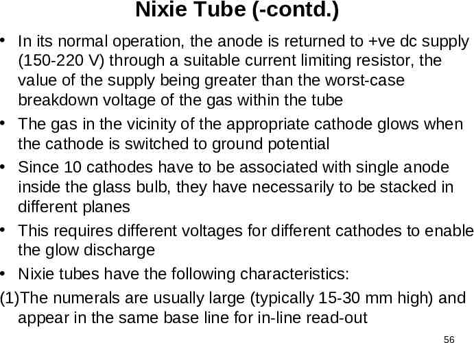
Nixie Tube (-contd.) In its normal operation, the anode is returned to ve dc supply (150-220 V) through a suitable current limiting resistor, the value of the supply being greater than the worst-case breakdown voltage of the gas within the tube The gas in the vicinity of the appropriate cathode glows when the cathode is switched to ground potential Since 10 cathodes have to be associated with single anode inside the glass bulb, they have necessarily to be stacked in different planes This requires different voltages for different cathodes to enable the glow discharge Nixie tubes have the following characteristics: (1)The numerals are usually large (typically 15-30 mm high) and appear in the same base line for in-line read-out 56
Nixie Tube (-contd.) (2) Nixie tubes are single digit devices with or without a decimal point (3) The selected cathode carries current in the range of 1-5 mA (4) The Nixie tube can be pulse operated & hence can be used in multiplexed displays Applications: Nixies were used as numeric displays in early digital frequency counters, voltmeters, & many other types of technical equipments They also appeared in costly digital time displays in research and military establishments Later, alphanumeric versions in 14-segment display format found use in airport arrival/departure signs & stock-ticker displays 57
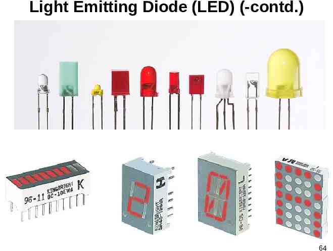
Light Emitting Diode (LED) LED is a diode that gives off visible light when it is biased properly & the mechanism of electromagnetic radiation (injection luminescence) takes place This occurs in two steps: (i) injection of minority carriers across the junction, and (ii) the radiative recombination of minority carriers Two types of radiative recombination mechanisms are commonly encountered in LEDs depending upon the band-gap characteristics of the semiconductor material used, i.e., (a) direct recombination, & (b) indirect recombination The emission of photons as a result of recombination of electrons & holes is possible only when both energy & momentum are conserved The simplest & most probable recombination process will be that where the electrons & holes have the same (i.e., zero) value of momentum which is the case of direct band-gap materials (e.g., GaP, GaN, GaAsP, Si2N3 etc) and the released light energy (photon in visible spectrum) 58
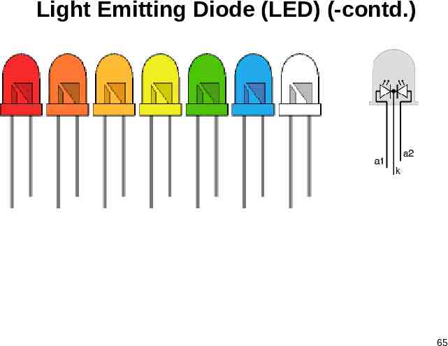
Light Emitting Diode (LED) (-contd.) In indirect band-gap materials (e.g., Si, Ge, SiC, etc.) the conduction band minima and valence band maxima occur at different values of momentum and the recombination of electrons & holes result into emission of energy into heat (phonons, which conserve momentum) and light (photons, not in visible range) The probability of recombination in this case is obviously much lower than that in direct band-gap semiconductors GaP is mainly used for emissions in the visible spectrum, it has a gap energy of 2.26 eV and can be doped with ZnO to give red light or with N2 to give green light LEDs are also housed in plastic bulb (the round end) that concentrate the light in a particular direction LEDs are used extensively in segmental & dot matrix displays of numeric & alphanumeric characters 59
Light Emitting Diode (LED) (-contd.) Advantages of LEDs in Electronic Displays: (i) LEDs are miniature in size & they can be stacked together to form numeric & alphanumeric displays in high density matrix (ii) The light output from an LED is a function of current flowing through it, therefore, intensity of light emitted can be smoothly controlled (iii)LEDs require moderate power (1.2 V of emf & 20 mA of current) for their operation (full brightness) (iv)LEDs are very fast as they have switching time less than 1 ns (v) LEDs are rugged & can therefore withstand shocks and vibrations, they can also operate over a wide range of temperature (0-700 C) (vi)LEDs don’t have a filament that will burn out, so they last much longer (more than 100000 hrs) 60
Light Emitting Diode (LED) (-contd.) 61
Light Emitting Diode (LED) (-contd.) 62
Light Emitting Diode (LED) (-contd.) 63
Light Emitting Diode (LED) (-contd.) 64
Light Emitting Diode (LED) (-contd.) 65
Liquid Crystal Display (LCD) A liquid crystal is a material (normally organic for LCDs) that flows like a liquid but whose molecular structure has some properties associated with solids, i.e., liquid crystals are substances that exist in an odd state: sort of like a liquid & sort of like a solid Thus, their molecules tend to maintain their orientation (like the molecules in a solid) but also move around to different positions (like the molecules in a liquid) Depending on the temperature & particular nature of a substance, liquid crystals can be in one of the several distinct phases, whose nematic phase makes LCDs possible Liquid crystals are affected by electric current A particular type of nematic liquid crystal, called twisted nematic (TN), is naturally twisted and applying a varying electric current to these liquid crystals will untwist them to varying degrees LCDs use these liquid crystals because they react predictably to electric current in such a way as to control light passage 66
Liquid Crystal Display (LCD) (-contd.) Types of LCDs: (1) Dynamic Scattering Type (Nematic Crystal) (2) Field Effect Type (Twisted Nematic Crystal) (1) Dynamic Scattering Type (Nematic Crystal): As shown in fig. 1 (a) & (b), the individual molecules have a rod like appearance The liquid crystals are layered between glass sheets with transparent electrodes (Indium Oxide) deposited on the inside faces Under no bias condition, the incident light will pass through & the liquid crystal structure appears clear If a voltage (6-20 V) is applied across the conducting surfaces, the molecular arrangement is disturbed and regions of different refractive indices are established which reflect the incident light in different directions at the interface of different refractive indices This phenomenon is referred to as dynamic scattering and causes a frosted-glass (bright) appearance 67
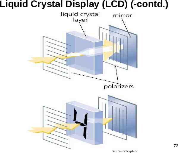
Liquid Crystal Display (LCD) (-contd.) The LCD does not generate its own light but depends on a external or internal light source Therefore, during the day or in lighted areas, a reflector can be put behind LCD to reflect light back (reflective mode) & under dark condition, the LCD must have its own internal light source either behind or side of LCD (transmissive mode) (2) Field Effect Type (Twisted Nematic Crystal): The construction of field effect LCD is similar to that of dynamic scattering type with the exception that two thin polarizing optical filters are placed at the outside of each glass sheet Similar to dynamic scattering LCD, the field effect can be operated in the reflective or transmissive mode In case of transmissive field effect LCD, the internal light source is on the right & the viewer on the left as shown in fig. 2(a) Only the vertical component of the incident light can pass through the vertical polarizer 68
Liquid Crystal Display (LCD) (-contd.) In between the two walls of the liquid crystal, there is a general drift from one polarization to the other The left-hand vertical light polarizer only permits the passage of vertical polarized light If there is no applied voltage then the viewer sees a uniformly dark pattern across the entire display but when a threshold voltage is applied (2-8 V), the rod like molecules align themselves with the field (perpendicular to the wall) and the light passes directly through without the 900 shift and can pass through the second vertically polarizer and the light area is seen by the viewer Through proper excitation of the segments of each digit, the pattern will appear In case of reflective type field effect LCD, the horizontally polarized light at the far left encounters a horizontally polarized filter and passes through to the other vertical polarization, & returned to the observer If there is no applied voltage, there is a uniformly lit display 69
Liquid Crystal Display (LCD) (-contd.) The application of a voltage results in a vertically polarized incident light encountering a horizontally polarized filter at the left which will not be able to pass through and be reflected which results a dark area on the crystal and the pattern Field effect LCDs are normally used when a source of energy is prime factor (e.g. in watches, cell phones, portable instruments, etc.), since they consume very small power (in µW range) as compared to the dynamic scattering types (in mW range) The cost is higher for field effect LCDs and their height is limited to about 2”, while dynamic scattering LCDs are available upto 8” in height 70
Liquid Crystal Display (LCD) (-contd.) Advantages of LCDs: They have low power (in µW) consumption as compared to LEDs (in mW) They have low cost Since the color generated by LCD units is dependent on the source of illumination, so there is greater range of color choice (16.8 million colors) Disadvantages of LCDs: They are very slow devices, having response time in the range of 100-300 ms They occupy a large area When operated on dc, their life-span is quite small because LCDs degrade chemically, therefore, they are used with ac supplies having a frequency less than 500 Hz 71
Liquid Crystal Display (LCD) (-contd.) 72
73
Liquid Crystal Display (LCD) (-contd.) 74
Liquid Crystal Display (LCD) (-contd.) 75
Liquid Crystal Display (LCD) (-contd.) 76
Liquid Crystal Display (LCD) (-contd.) 77
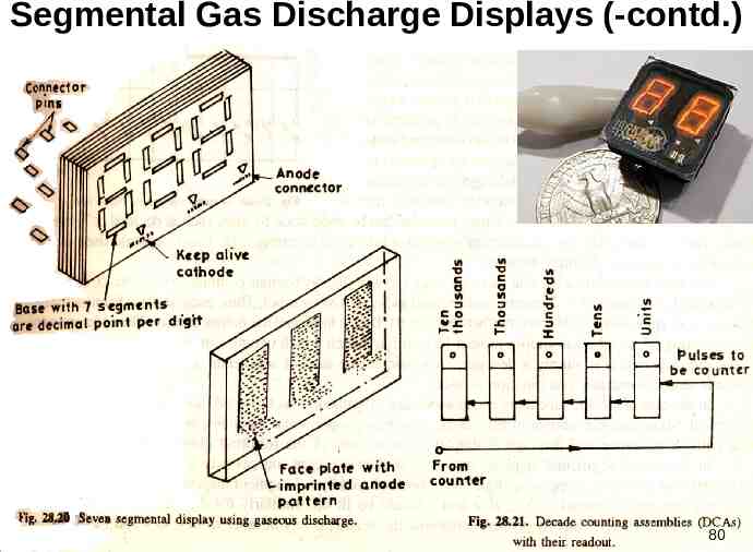
Segmental Gas Discharge Displays Segmented gas discharge displays work on the principle of gas discharge glow similar to Nixie tubes They are mostly available in 7 or 14-segment form to display numeric or alphanumeric characters As shown in figure, each segment (including decimal point) of the 7segment display formed on a base has a separate cathode The anode is common to each member of 7-segment group, which is deposited on the covering face plate The space between the anode & cathodes contains the gas For each group of segments, a “keep alive” cathode is also provided, which improves the switching speed of the display by passing a small constant current (few µA) through it and acts as source of ions Pins are connected to the electrodes at the rear of the base plate with the help of which external connections can be made Figure shows the structure of a 7-segment display making the use of gas discharge plasma 78
Segmental Gas Discharge Displays (-contd.) Back electrodes of the thick film type serve as cathode segments & front electrodes of the thin film type serve as transparent anodes A gas (typically Neon) is filled in the discharge space between the cathode & anode segment The gas is struck between the cathode & anode of a chosen segment so that the cathode glow provides the illumination & characters can be displayed by activating the appropriate segments Advantages & Disadvantages: The power requirements of such devices are more or less in the same range as those for Nixie tubes (i.e., the power consumed is extremely small) The major disadvantage of this gas discharge tube is that high voltage (150220 V) is required for operating Therefore, high voltage transistors (special ICs) are required as switches for the cathodes 79
Segmental Gas Discharge Displays (-contd.) 80
Segmental Gas Discharge Displays (-contd.)