Andrew Marquez Advisor: Prof. Marc A. Meyers Materials Science


40 Slides5.47 MB
Andrew Marquez Advisor: Prof. Marc A. Meyers Materials Science and Engineering Program University of California, San Diego
Background Dynamic Testing Taylor Anvil Test Split-Hopkinson Bar Expanding Ring Technique Dynamic Mechanical Analysis (DMA) Cam Plastometer Summary and Conclusions
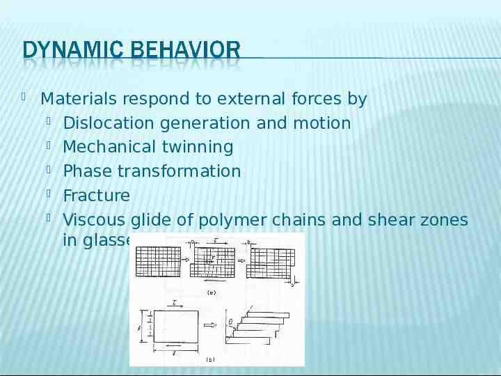
Materials respond to external forces by Dislocation generation and motion Mechanical twinning Phase transformation Fracture Viscous glide of polymer chains and shear zones in glasses
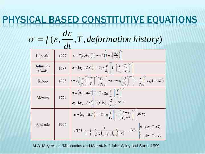
d f ( , , T , deformation history) dt M.A. Meyers, in “Mechanics and Materials,” John Wiley and Sons, 1999
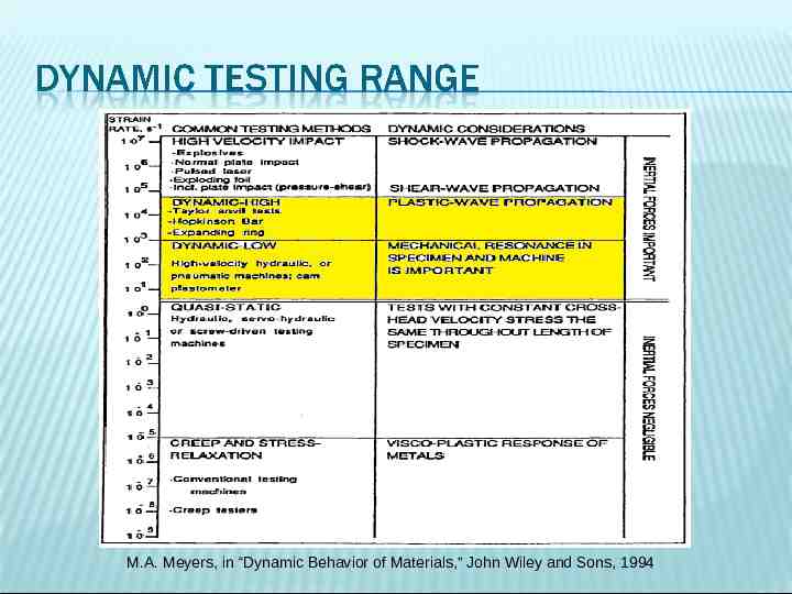
M.A. Meyers, in “Dynamic Behavior of Materials,” John Wiley and Sons, 1994
Taylor Anvil Test
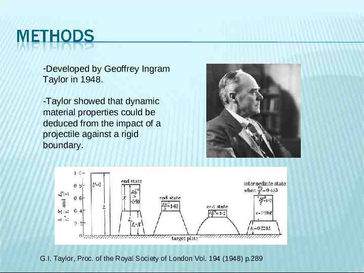
-Developed by Geoffrey Ingram Taylor in 1948. -Taylor showed that dynamic material properties could be deduced from the impact of a projectile against a rigid boundary. G.I. Taylor, Proc. of the Royal Society of London Vol. 194 (1948) p.289
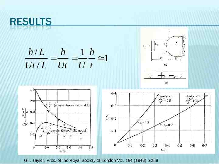
h/ L h 1 h 1 Ut / L Ut U t G.I. Taylor, Proc. of the Royal Society of London Vol. 194 (1948) p.289
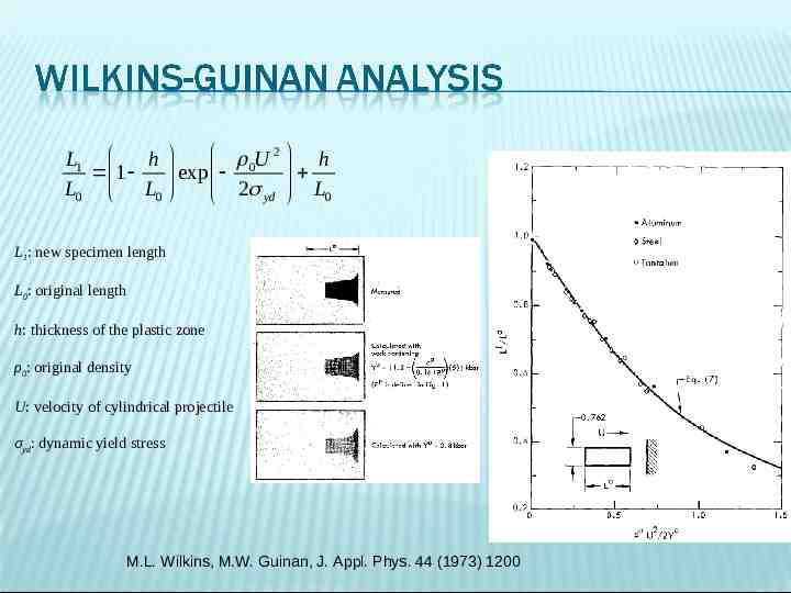
0U 2 h L1 h exp 1 2 L L0 L0 yd 0 L1: new specimen length L0: original length h: thickness of the plastic zone ρ0: original density U: velocity of cylindrical projectile σyd: dynamic yield stress M.L. Wilkins, M.W. Guinan, J. Appl. Phys. 44 (1973) 1200
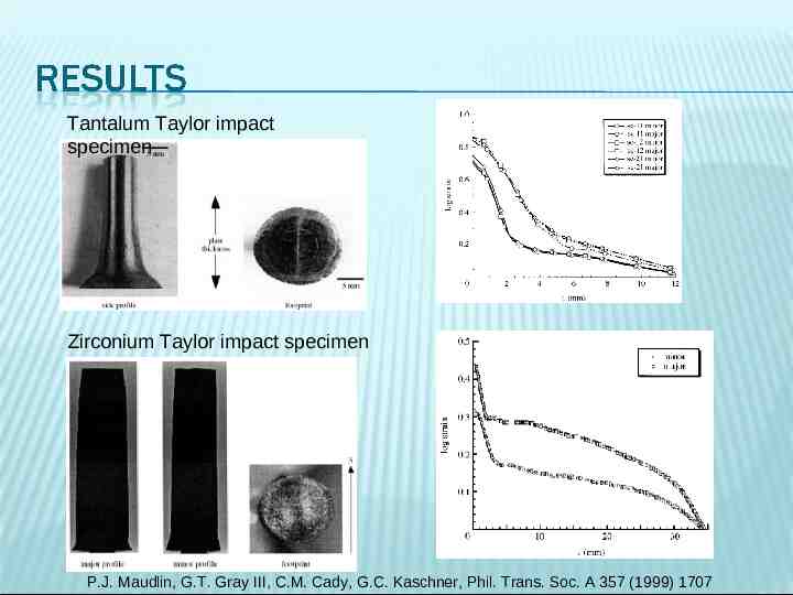
Tantalum Taylor impact specimen Zirconium Taylor impact specimen P.J. Maudlin, G.T. Gray III, C.M. Cady, G.C. Kaschner, Phil. Trans. Soc. A 357 (1999) 1707
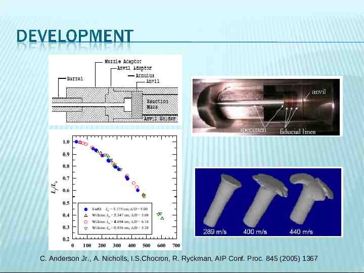
C. Anderson Jr., A. Nicholls, I.S.Chocron, R. Ryckman, AIP Conf. Proc. 845 (2005) 1367
Split-Hopkinson Bar
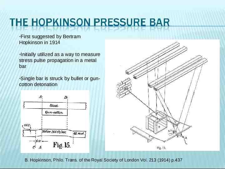
-First suggested by Bertram Hopkinson in 1914 -Initially utilized as a way to measure stress pulse propagation in a metal bar -Single bar is struck by bullet or guncotton detonation B. Hopkinson, Philo. Trans. of the Royal Society of London Vol. 213 (1914) p.437
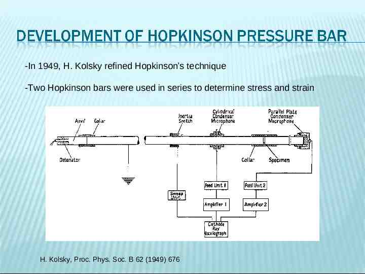
-In 1949, H. Kolsky refined Hopkinson’s technique -Two Hopkinson bars were used in series to determine stress and strain H. Kolsky, Proc. Phys. Soc. B 62 (1949) 676
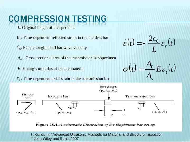
L: Original length of the specimen r: Time-dependent reflected strain in the incident bar c0: Elastic longitudinal bar wave velocity A0/S: Cross-sectional area of the transmission bar/specimen E: Young’s modulus of the bar material t : Time-dependent axial strain in the transmission bar 2c0 t r t L A0 t E t t As T. Kundu, in “Advanced Ultrasonic Methods for Material and Structure Inspection ,” John Wiley and Sons, 2007
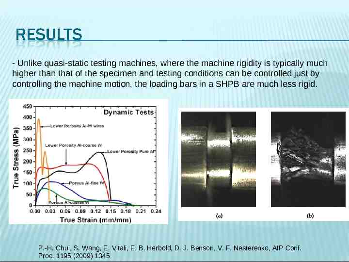
- Unlike quasi-static testing machines, where the machine rigidity is typically much higher than that of the specimen and testing conditions can be controlled just by controlling the machine motion, the loading bars in a SHPB are much less rigid. P.-H. Chui, S. Wang, E. Vitali, E. B. Herbold, D. J. Benson, V. F. Nesterenko, AIP Conf. Proc. 1195 (2009) 1345
http://bcove.me/vilofpvy
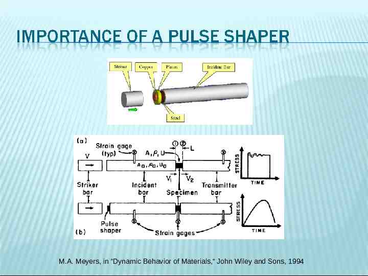
M.A. Meyers, in “Dynamic Behavior of Materials,” John Wiley and Sons, 1994
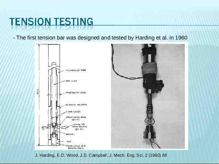
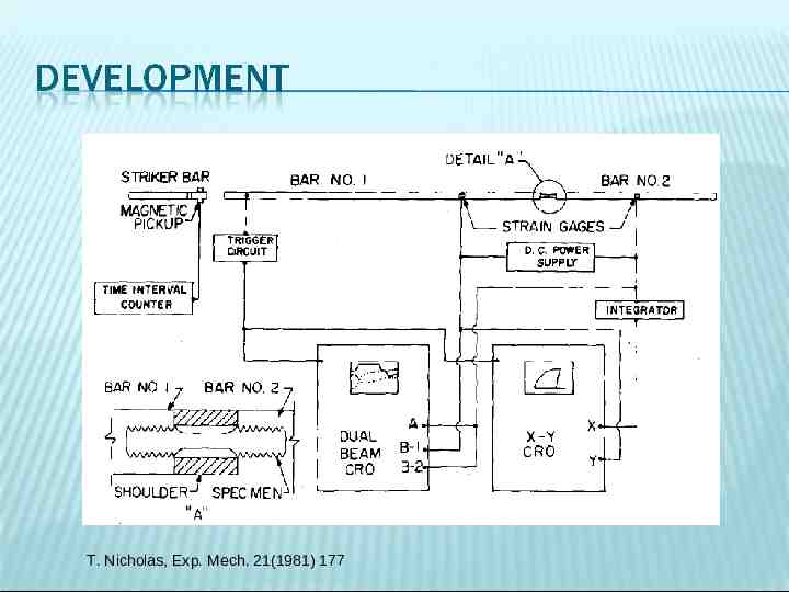
- The first tension bar was designed and tested by Harding et al. in 1960 J. Harding, E.O. Wood, J.D. Campbell, J. Mech. Eng. Sci. 2 (1960) 88
T. Nicholas, Exp. Mech. 21(1981) 177
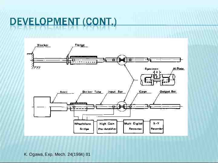
K. Ogawa, Exp. Mech. 24(1984) 81
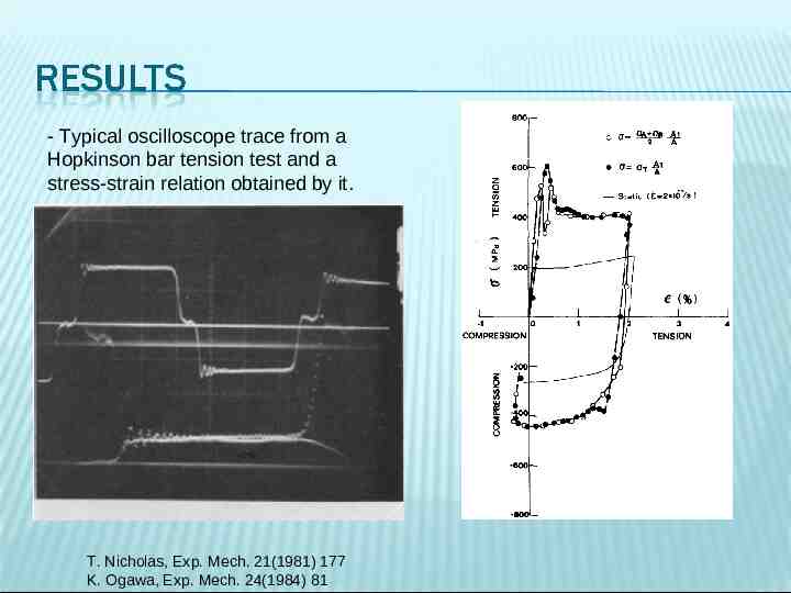
- Typical oscilloscope trace from a Hopkinson bar tension test and a stress-strain relation obtained by it. T. Nicholas, Exp. Mech. 21(1981) 177 K. Ogawa, Exp. Mech. 24(1984) 81
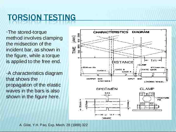
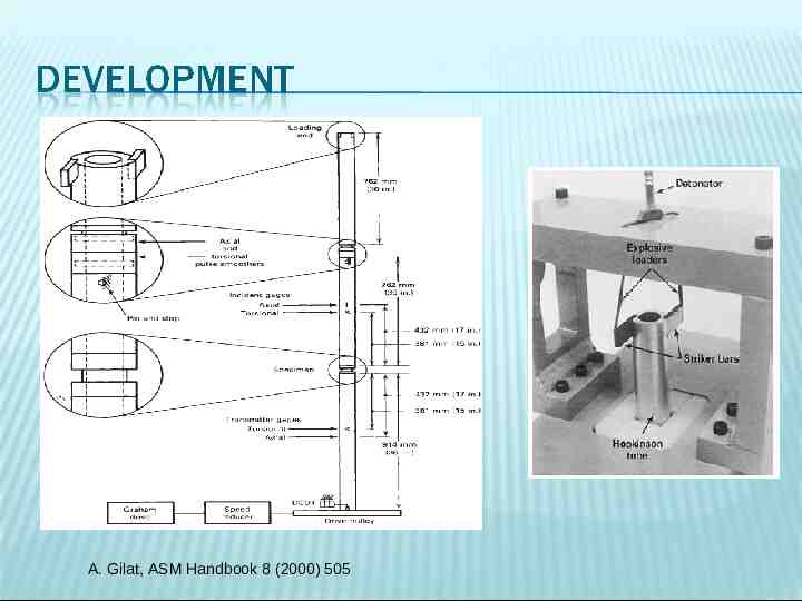
-The stored-torque method involves clamping the midsection of the incident bar, as shown in the figure, while a torque is applied to the free end. -A characteristics diagram that shows the propagation of the elastic waves in the bars is also shown in the figure here. A. Gilat, Y.H. Pao, Exp. Mech. 28 (1988) 322
A. Gilat, ASM Handbook 8 (2000) 505
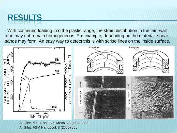
- With continued loading into the plastic range, the strain distribution in the thin-wall tube may not remain homogeneous. For example, depending on the material, shear bands may form. An easy way to detect this is with scribe lines on the inside surface. A. Gilat, Y.H. Pao, Exp. Mech. 28 (1988) 322 A. Gilat, ASM Handbook 8 (2000) 505
Expanding Ring Technique
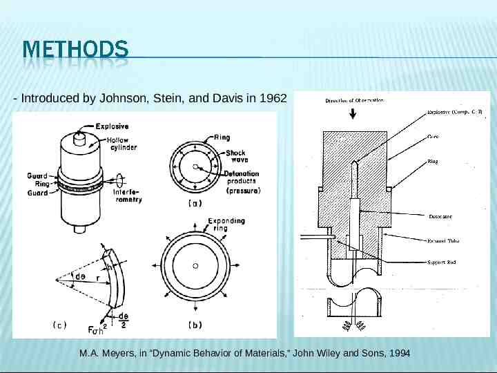
- Introduced by Johnson, Stein, and Davis in 1962 M.A. Meyers, in “Dynamic Behavior of Materials,” John Wiley and Sons, 1994
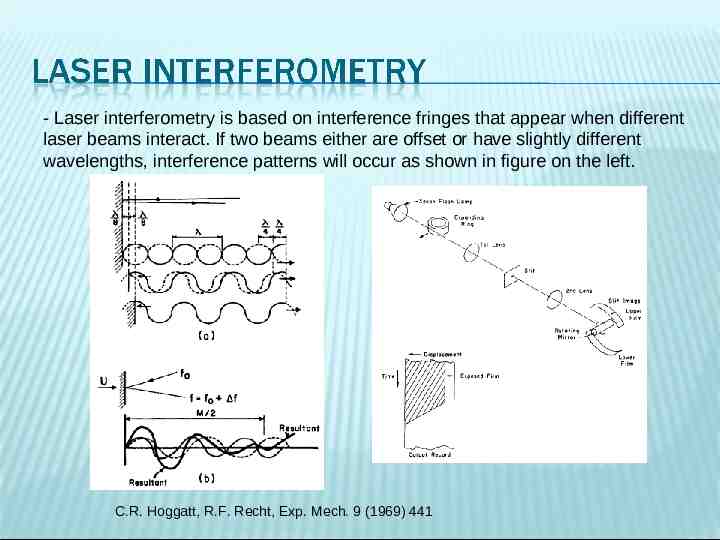
- Laser interferometry is based on interference fringes that appear when different laser beams interact. If two beams either are offset or have slightly different wavelengths, interference patterns will occur as shown in figure on the left. C.R. Hoggatt, R.F. Recht, Exp. Mech. 9 (1969) 441
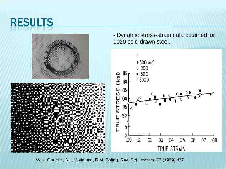
- Dynamic stress-strain data obtained for 1020 cold-drawn steel. W.H. Gourdin, S.L. Weinland, R.M. Boling, Rev. Sci. Instrum. 60 (1989) 427
Dynamic Mechanical Analysis (DMA)
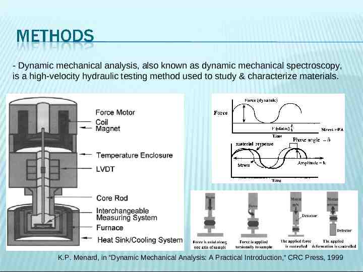
- Dynamic mechanical analysis, also known as dynamic mechanical spectroscopy, is a high-velocity hydraulic testing method used to study & characterize materials. K.P. Menard, in “Dynamic Mechanical Analysis: A Practical Introduction,” CRC Press, 1999
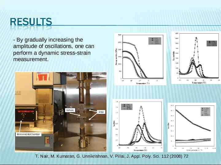
- By gradually increasing the amplitude of oscillations, one can perform a dynamic stress-strain measurement. T. Nair, M. Kumaran, G. Unnikrishnan, V. Pillai, J. Appl. Poly. Sci. 112 (2008) 72
Cam Plastometer
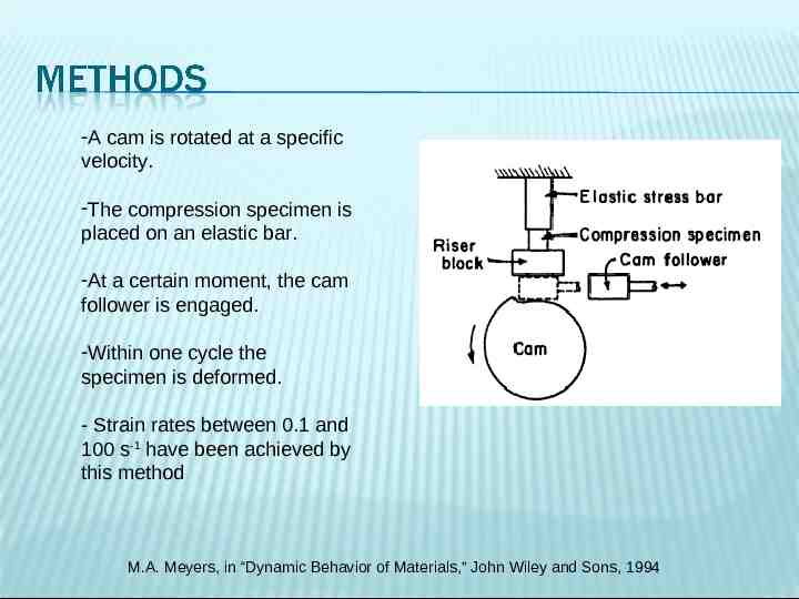
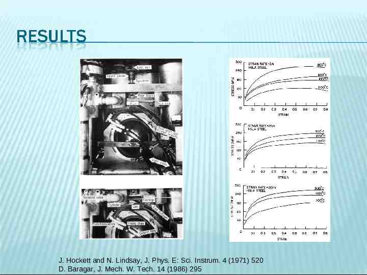
-A cam is rotated at a specific velocity. -The compression specimen is placed on an elastic bar. -At a certain moment, the cam follower is engaged. -Within one cycle the specimen is deformed. - Strain rates between 0.1 and 100 s-1 have been achieved by this method M.A. Meyers, in “Dynamic Behavior of Materials,” John Wiley and Sons, 1994
J. Hockett and N. Lindsay, J. Phys. E: Sci. Instrum. 4 (1971) 520 D. Baragar, J. Mech. W. Tech. 14 (1986) 295
In the strain rate range of 101-103 s-1 machines such as the cam plastometer and DMA are used. In the strain rate range of 103-105 s-1 the expanding ring, the Hopkinson bar, and the Taylor test are used. There are advantages and disadvantages such as ease of operation, sample preparation, and cost that must be weighed for dynamic testing of specific materials in certain strain rate ranges. Thus, the optimal method for examination can be determined for dynamic material properties.
THANK YOU FOR YOUR ATTENTION
M.A. Meyers, in “Mechanics and Materials,” John Wiley and Sons, 1999 G.I. Taylor, Proc. of the Royal Society of London Vol. 194 (1948) p.289 M.L. Wilkins, M.W. Guinan, J. Appl. Phys. 44 (1973) 1200 P.J. Maudlin, G.T. Gray III, C.M. Cady, G.C. Kaschner, Phil. Trans. Soc. A 357 (1999) 1707 C. Anderson Jr., A. Nicholls, I.S.Chocron, R. Ryckman, AIP Conf. Proc. 845 (2005) 1367 B. Hopkinson, Philo. Trans. of the Royal Society of London Vol. 213 (1914) p.437 H. Kolsky, Proc. Phys. Soc. B 62 (1949) 676 T. Kundu, in “Advanced Ultrasonic Methods for Material and Structure Inspection,” John Wiley and Sons, 2007 P.-H. Chui, S. Wang, E. Vitali, E. B. Herbold, D. J. Benson, V. F. Nesterenko, AIP Conf. Proc. 1195 (2009) 1345 J. Harding, E.O. Wood, J.D. Campbell, J. Mech. Eng. Sci. 2 (1960) 88 T. Nicholas, Exp. Mech. 21(1981) 177 K. Ogawa, Exp. Mech. 24(1984) 81 A. Gilat, Y.H. Pao, Exp. Mech. 28 (1988) 322 A. Gilat, ASM Handbook 8 (2000) 505 C.R. Hoggatt, R.F. Recht, Exp. Mech. 9 (1969) 441 W.H. Gourdin, S.L. Weinland, R.M. Boling, Rev. Sci. Instrum. 60 (1989) 427 K.P. Menard, in “Dynamic Mechanical Analysis: A Practical Introduction,” CRC Press, 1999 T. Nair, M. Kumaran, G. Unnikrishnan, V. Pillai, J. Appl. Poly. Sci. 112 (2008) 72 J. Hockett and N. Lindsay, J. Phys. E: Sci. Instrum. 4 (1971) 520 D. Baragar, J. Mech. W. Tech. 14 (1986) 295