TAPR: Tomorrow’s Ham Radio Technology Today John Ackermann,


25 Slides474.00 KB
TAPR: Tomorrow’s Ham Radio Technology Today John Ackermann, N8UR Tucson Amateur Packet Radio, Inc.
Who am I? A ham for 25 years (ex-AG9V, WB9OWI) A lawyer by trade, working for NCR Corp. Active in DXing and Contesting, but became interested in packet radio, joined TAPR, and never looked back – Board member and VP since 1995 – Elected President in 2000 Contact Information: [email protected] or [email protected] http://www.febo.com 01 937 445-2966
What is TAPR? Founded in Tucson, Arizona in early 1980s; quickly became an international organization Today, over 2000 members worldwide Contact Information: 8987-309 E. Tanque Verde Road Tucson, AZ 85749-9399 USA 01 940 383-0000 [email protected] http://www.tapr.org
Previous TAPR Projects/Products TNC-1 -- the project that started it all TNC-2 -- the “standard” TNC – OEM’d by AEA, MFJ, PacComm, and others TrakBox (satellite antenna tracker, with AMSAT) DSP-93 (early DSP modem) 9600 Baud Modem Many Others
TAPR Today Focused on “Enabling Technology” – Tools that let hams continue to be on the leading edge Major Projects: – FHSS Spread Spectrum Radio – Software Defined Radio – PIC-based Project Kits Co-Sponsor (with ARRL) of the annual Digital Communications Conference
Current Products PIC-E -- Universal Packet Radio Encoder T-238 -- One-Wire Weather Station Compact Flash Adapter II Totally Accurate Clock METCON-2 -- Universal Remote Control/Sensor EZ-Trak -- New Generation Satellite Antenna Tracker
Books and Publications PSR -- TAPR’s Quarterly Journal DCC Proceedings Wireless Digital Communications: Design and Theory by Tom McDermott, N5EG Networking Without Wires: TCP/IP over Amateur Radio by John Ackermann, N8UR Spread Spectrum Update edited by Greg Jones, WD5IVD and Steve Bible, N7HPR
TAPR’s Online Presence http://www.tapr.org Mailing lists: – – – – [email protected] (APRS) [email protected] (Packet Networking) [email protected] (Spread Spectrum) Many, many others File Downloads – APRS software, etc.
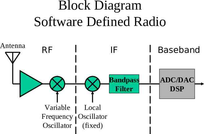
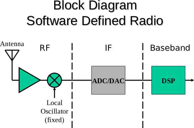
What Is a Software Defined Radio (SDR)? Performs the majority of signal processing in the digital domain using programmable DSPs and hardware support, but some signal processing is still done in the analog domain, such as in the RF and IF circuits.
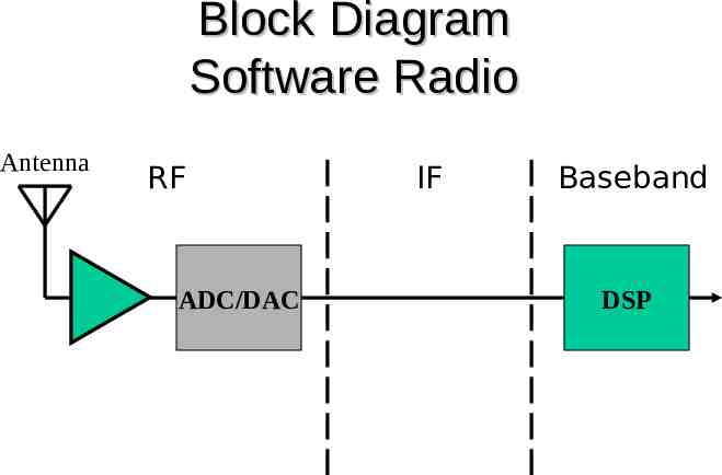
What Is a Software Radio (SW)? The ultimate device, where the antenna is connected directly to an A-D/D-A converter and all signal processing is done digitally using fully programmable high speed DSPs. All functions, modes, applications, etc. can be reconfigured by software.
Why Software Defined Radios? Dale Hatfield, WØIFO, Chief, Office of Engineering and Technology, Federal Communications Commission “This could stimulate a whole new generation of amateur innovation that not only includes the more spectrally efficient systems I mentioned earlier, but also radios that could adapt to their environment as well.” Speech to AMRAD’s 25th Anniversary Dinner June 17, 2000 http://www.fcc.gov/Speeches/misc/dnh061700.html
Benefits of SDR Flexible Reduced Obsolescence Enhances Experimentation Brings Analog and Digital World Together
New Breed of Radio Reprogrammable Multiband/Multimode Networkable Simultaneous voice, data, and video Full convergence of digital networks and radio science.
Block Diagram Software Defined Radio Antenna RF IF Bandpass Filter Variable Local Frequency Oscillator Oscillator (fixed) Baseband ADC/DAC DSP
Block Diagram Software Defined Radio Antenna RF Local Oscillator (fixed) IF Baseband ADC/DAC DSP
Block Diagram Software Radio Antenna RF ADC/DAC IF Baseband DSP
Looking Ahead Smart Radios that configure themselves to perform the communications task requested (using different frequency bands, modes, etc.) Cognitive Radios that learn about their environment (e.g., other users nearby, interference, location, elevation) to optimally configure themselves to maximize efficiency and reduce interference.
Technical Challenges Dynamic Radio ADC/DAC Speed Smart Radio Algorithms
How to Build a SDR DSP-10 by Bob Larkin, W7PUA QST - Sep, Oct, Nov 1999 http://www.proaxis.com/ boblark/dsp10.htm http://www.arrl.org/tis/info/vhfproj.html R2-DSP by Rob Frohne, KL7NA QST - Apr 1998 http://www.wwc.edu/ frohro/R2 DSP/R2-DSP.html A Panoramic Transceiving System for PSK31 by Skip Teller, KH6TY and Dave Benson, NN1G QST - Jun 2000 http://www.arrl.org/tis/info/psk31.html (see also the new 80M “Whistler” radio by the same folks)
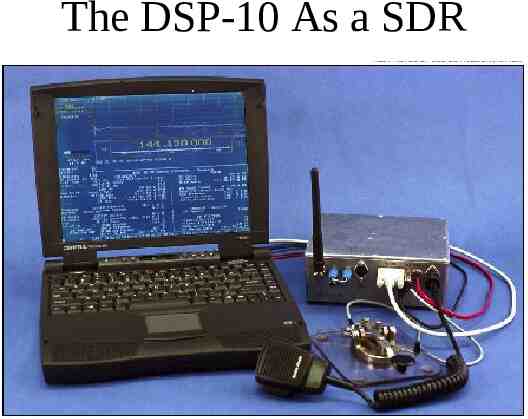
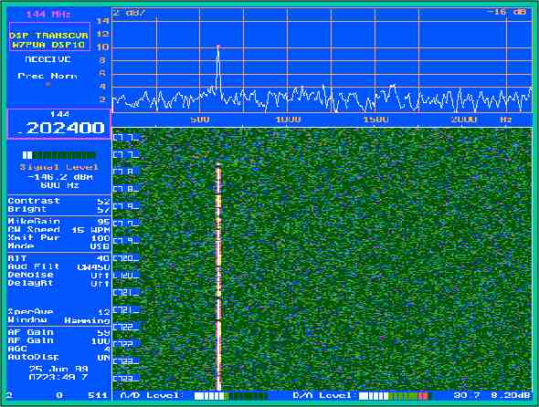
The DSP-10 As a SDR
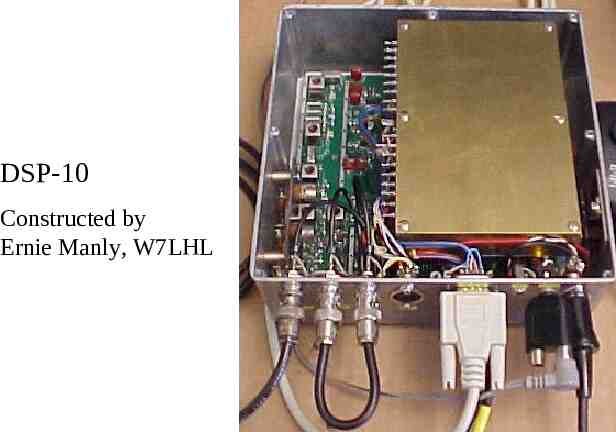
DSP-10 Constructed by Ernie Manly, W7LHL
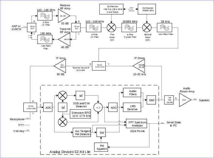
143 - 149 MHz Receive RF Amp Synthesizer 124.3 to 128.4 MHz 5 kHz Steps 10 MHz Ext. Ref. (Optional) Synthesizer 19.680 MHz U1,U2 R ANT or XVRTR TR SW (D2) J211 J212 T 2-Pole LC Filter 150 MHz 32 dB Transmit RF Amp 143 - 149 MHz R 19.665 MHz TR SW (D1) T 4-Pole LC Filter J213 First Mixer U4,U5 Low-Pass Filter R Receiver Second IF 10-20 kHz TR SW (U11A,U11C) (U15) T U109B, Q5,Q6 10-20 kHz Audio Power Amp Audio Filters o 90 TR SW (U11B) DAC R ADC o 90 SSB and CW Detector /- AGC R LMS Denoise Sinewave BFO 12.5 -17.5 kHz J102 FFT Spectrum Analyzer PTT CW Key Low-Pass Filter IF Driver 50 dB Microphone Second Mixer 40 dB Q1, U10A T 4-Pole Crystal Filter (U3) IF Amp TR SW (U12A,U12B) 28 kHz J103 Arc Tangent FM Detector Analog Devices EZ-Kit Lite SW FM Squelch 1024 Points J201 Serial Data to PC U14 J204 Speaker
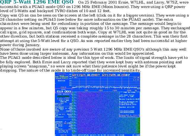
QRP 5-Watt 1296 EME QSO On 25 February 2001 Ernie, W7LHL, and Larry, W7SZ, were successful with a PUA43 mode QSO on 1296 MHz EME (Moon bounce). They were using a QRP power level of 5-Watts and backyard TVRO dishes of 10 and 12 feet. Copy was Q5 as can be seen on the screen at the left (click on it for a bigger version). They were using a 28 character setting on PUA43 (see below for more information on the PUA43 mode). The extra characters were being used for redundancy in portions of the message. The message would begin to appear in a few minutes, but Q5 copy was taking roughly 15 to 30 minutes per message. They exchanged call signs, grid squares, and confirmations both ways. Copy at W7LHL was not quite as good as for the other direction, but both stations received a complete message in the 28 characters. This was their first attempt at using the 5-Watt level for a QSO. As was reported earlier they had been successful at higher power during January. None of those involved are aware of any previous 5 Watt 1296 MHz EME QSO's although this may well have been done using larger antennas. Any information on this would be appreciated. The PUA43 mode described below is ideal for this type of work. The limits of signal strength have yet to be fully explored. Both Ernie and Larry reported that they were kept busy with antenna pointing and playing screen "anagrams," so were not sure what their patience level might be if the power kept dropping. The nature of the mode is to trade-off time for increased sensitivity.
Single Yagi, 150 Watt 2-Meter EME QSO W7SLB and W7PUA demonstrated a QSO on 2-meter EME, using the PUA43 mode of the DSP-10. Single Yagis and transmitter powers of 150 Watts or less were used on both ends of the contact. Details are available on the weak signals page and the linked text