POLYPHASE CIRCUITS LEARNING GOALS Three Phase Circuits Advantages of


17 Slides438.50 KB
POLYPHASE CIRCUITS LEARNING GOALS Three Phase Circuits Advantages of polyphase circuits Three Phase Connections Basic configurations for three phase circuits Source/Load Connections Delta-Y connections Power Relationships Study power delivered by three phase circuits Power Factor Correction Improving power factor for three phase circuits
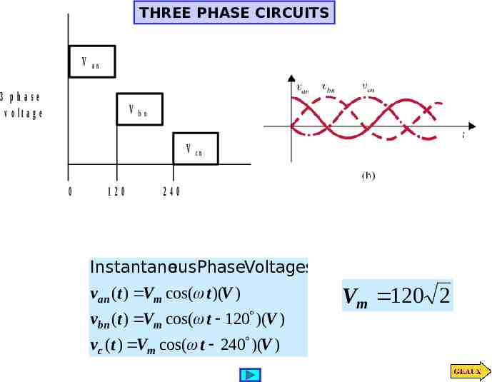
THREE PHASE CIRCUITS V an 3 phase v o lta g e V bn V 0 120 cn 240 Instantane ousPhaseVoltages van (t ) Vm cos( t )(V ) vbn (t ) Vm cos( t 120 )(V ) vc (t ) Vm cos( t 240 )(V ) Vm 120 2
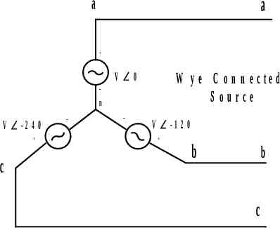
a a W y e C o n n e c te d S ource V 0 n V -2 4 0 c V -1 2 0 b b c
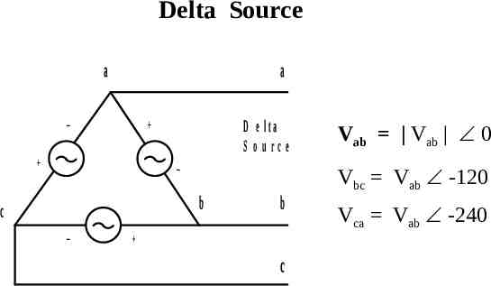
Delta Source a a D e lta S o urce b c b c Vab Vab 0 Vbc Vab -120 Vca Vab -240
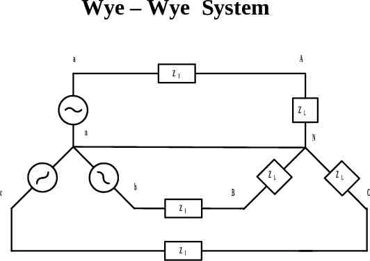
Wye – Wye System a A Z l ZL n c N ZL b B Z l Z l ZL C
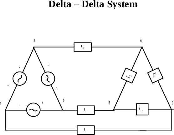
Delta – Delta System a A Z l c L ZL Z b B Z l Z l C ZL
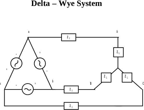
Delta – Wye System a A Z ZL c l ZL b B Z l Z l ZL C
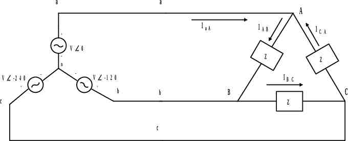
a a IaA A V 0 n V -2 4 0 IC Z Z IB V -1 2 0 IAB b b c C C B Z c A
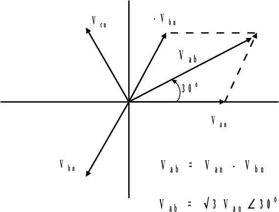
V cn - V bn V ab 30 o V V bn V V an ab V ab 3 V an - V an bn 30o
Vab Van Vbn V p 0 V p 120 V p 1 (cos120 j sin 120) 1 3 V p V p j 2 2 3 V p 30 Vbc 3 V p 90 Vca 3 V p 210 VL 3 V p Line Voltage
IC 3 I A B -3 0 o IaA A IAB IaA IB C - IC A
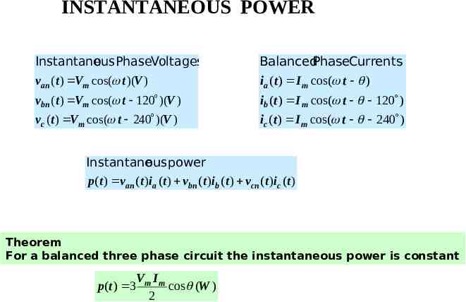
INSTANTANEOUS POWER Instantane ousPhaseVoltages van (t ) Vm cos( t )(V ) BalancedPhaseCurrents ia (t ) I m cos( t ) vbn (t ) Vm cos( t 120 )(V ) ib ( t ) I m cos( t 120 ) vc (t ) Vm cos( t 240 )(V ) ic (t ) I m cos( t 240 ) Instantane ous power p(t ) van (t )ia (t ) vbn ( t ) ib ( t ) vcn ( t )ic (t ) Theorem For a balanced three phase circuit the instantaneous power is constant p(t ) 3 Vm I m cos (W ) 2
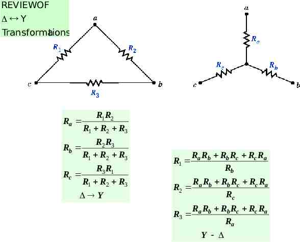
REVIEWOF Y Transforma tions Ra R1R2 R1 R2 R3 Rb R2 R3 R1 R2 R3 Rc R3 R1 R1 R2 R3 Y R1 Ra Rb Rb Rc Rc Ra Rb R2 Ra Rb Rb Rc Rc Ra Rc R3 Ra Rb Rb Rc Rc Ra Ra Y
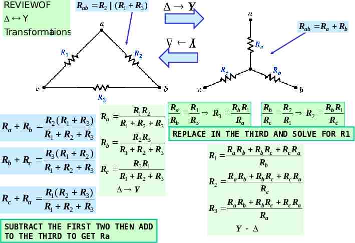
REVIEWOF Rab R2 ( R1 R3 ) Y Transforma tions Y Rab Ra Rb Y Ra R1 Rb R1 Rb R2 Rb R1 R1R2 R R 3 2 Ra Rc R1 Rc R2 ( R1 R3 ) Ra R1 R2 R3 Rb R3 Ra Rb REPLACE IN THE THIRD AND SOLVE FOR R1 R1 R2 R3 R2 R3 Rb R1 R2 R3 Ra Rb Rb Rc Rc Ra R3 ( R1 R2 ) R 1 Rb Rc Rb R R 3 1 R1 R2 R3 Rc R1 R2 R3 R R Rb Rc Rc Ra R2 a b Rc Y R (R R ) Rc Ra 1 2 3 R1 R2 R3 SUBTRACT THE FIRST TWO THEN ADD TO THE THIRD TO GET Ra R3 Ra Rb Rb Rc Rc Ra Ra Y
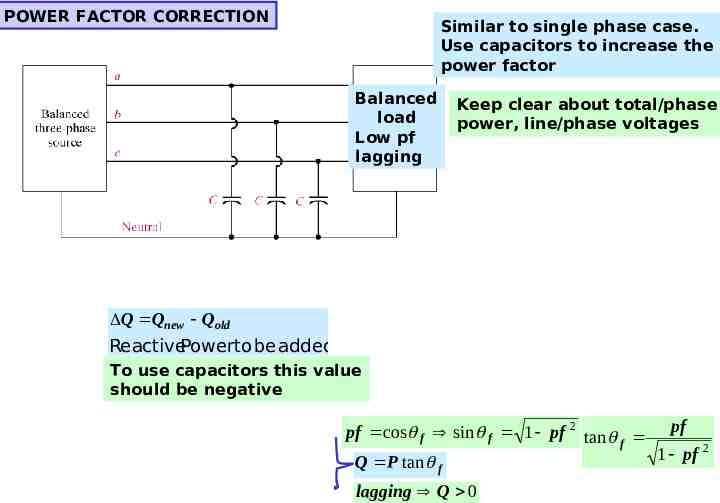
POWER FACTOR CORRECTION Similar to single phase case. Use capacitors to increase the power factor Balanced load Low pf lagging Keep clear about total/phase power, line/phase voltages Q Qnew Qold ReactivePowerto be added To use capacitors this value should be negative pf cos f sin f 1 pf 2 tan pf f 1 pf 2 Q P tan f lagging Q 0
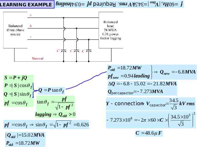
f 60 Hz , Vline 34.5kV rms. Required: pf 0.94 leading LEARNING EXAMPLE Pold 18.72 MW S P jQ P S cos f Q S sin f pf cos f Q P tan f tan f pf 1 pf 2 lagging Qold 0 pf cos f sin f 1 pf 2 0.626 Qold 15.02 MVA Pold 18.72 MW Qnew 6.8 MVA pf new 0.94 leading Q 6.8 15.02 21.82 MVA Qper capacitor 7.273MVA 34.5 Y connection Vcapacitor kV rms 3 34.5 103 6 7.273 10 2 60 C 3 C 48.6 F 2
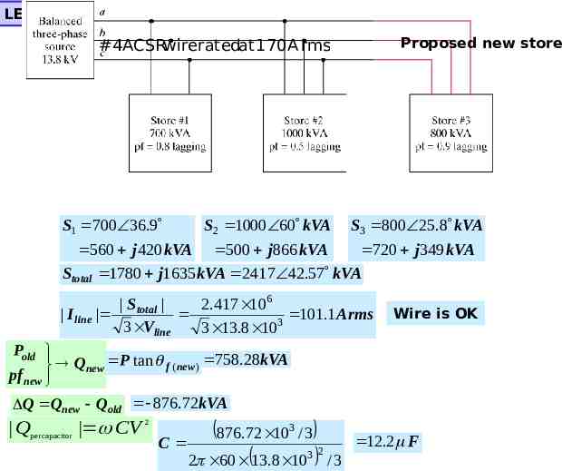
LEARNING BY DESIGN Proposed new store #4ACSRwireratedat 170A rms S1 700 36.9 S2 1000 60 kVA S3 800 25.8 kVA 560 j 420 kVA 500 j866 kVA 720 j 349 kVA Stotal 1780 j1635 kVA 2417 42.57 kVA S total 2.417 106 I line 101.1A rms 3 3 Vline 3 13.8 10 Wire is OK Pold Qnew P tan f ( new ) 758.28kVA pf new Q Qnew Qold 876.72kVA Q per capacitor CV 2 876.72 10 / 3 C 2 60 13.8 10 3 3 2 12.2 F /3