NC PART PROGRAMMING IE550 Fall 2001 IE550
47 Slides309.00 KB
NC PART PROGRAMMING IE550 Fall 2001 IE550
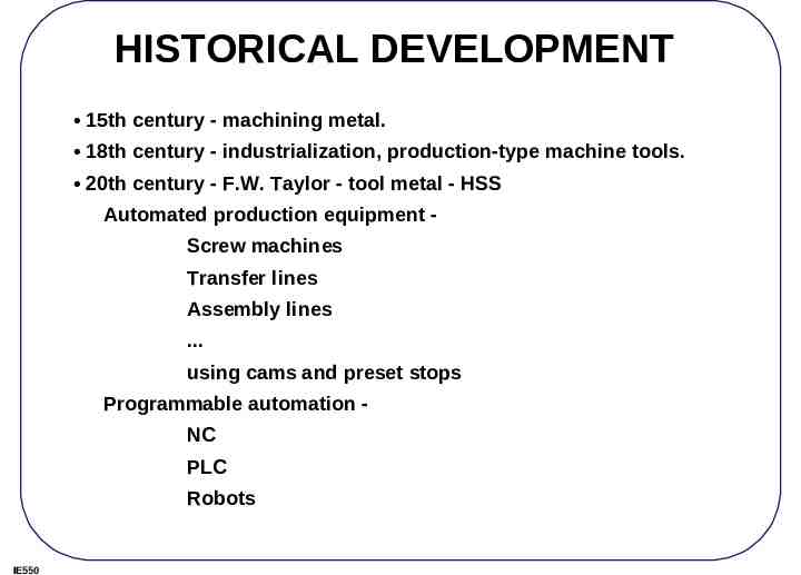
HISTORICAL DEVELOPMENT 15th century - machining metal. 18th century - industrialization, production-type machine tools. 20th century - F.W. Taylor - tool metal - HSS Automated production equipment Screw machines Transfer lines Assembly lines . using cams and preset stops Programmable automation NC PLC Robots IE550
NEW NCs or CNCs high speed spindle ( 20,000 rpm) high feed rate drive ( 600 ipm) high precision ( 0.0001" accuracy) IE550
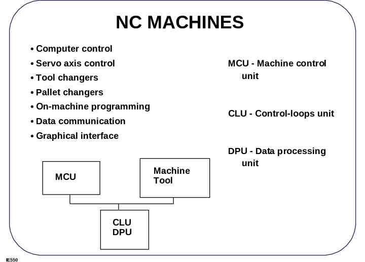
NC MACHINES Computer control Servo axis control MCU - Machine control unit Tool changers Pallet changers On-machine programming CLU - Control-loops unit Data communication Graphical interface Machine Tool MCU CLU DPU IE550 DPU - Data processing unit
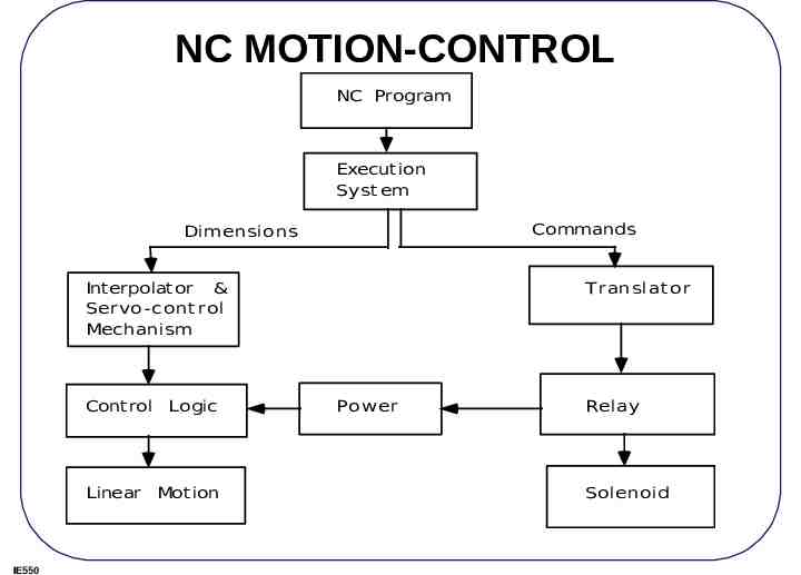
NC MOTION-CONTROL NC Program Execution Syst em Commands Dimensions Interpolator & Servo-cont rol Mechanism Control Logic Linear Motion IE550 T ranslat or Power Relay Solenoid
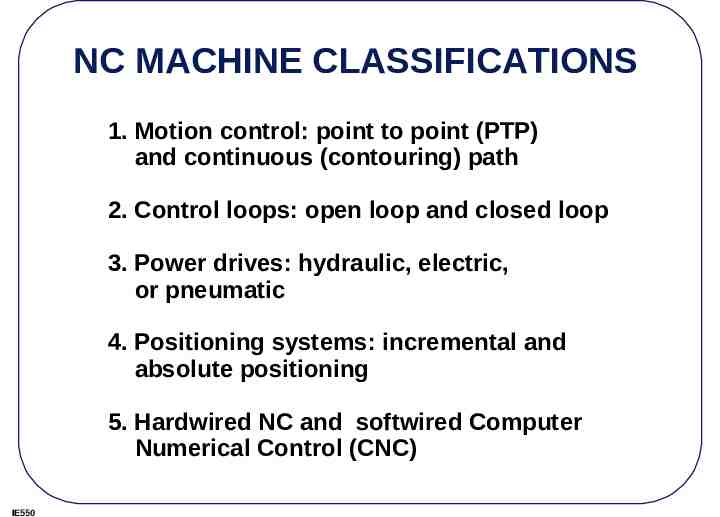
NC MACHINE CLASSIFICATIONS 1. Motion control: point to point (PTP) and continuous (contouring) path 2. Control loops: open loop and closed loop 3. Power drives: hydraulic, electric, or pneumatic 4. Positioning systems: incremental and absolute positioning 5. Hardwired NC and softwired Computer Numerical Control (CNC) IE550
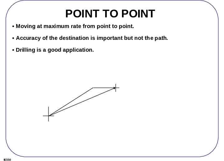
POINT TO POINT Moving at maximum rate from point to point. Accuracy of the destination is important but not the path. Drilling is a good application. IE550
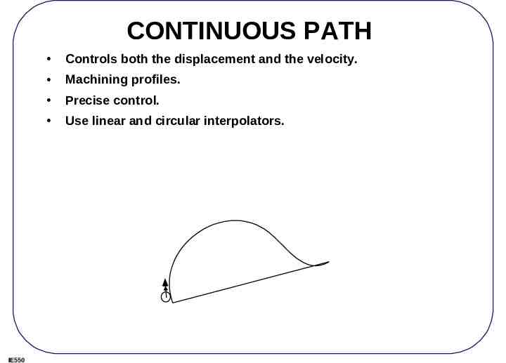
CONTINUOUS PATH IE550 Controls both the displacement and the velocity. Machining profiles. Precise control. Use linear and circular interpolators.
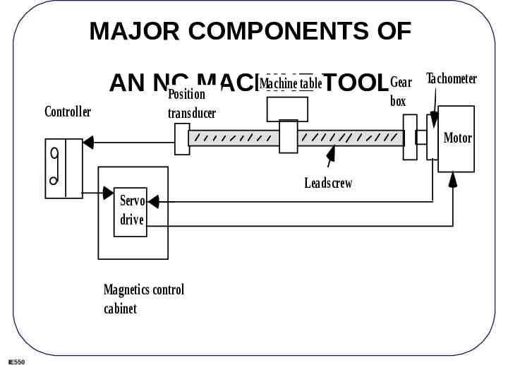
MAJOR COMPONENTS OF Machine tableTOOLGear AN NC MACHINE Position Controller Tachometer box transducer Motor Leadscrew Servo drive Magnetics control cabinet IE550
NC MACHINE RATING Accuracy Repeatability Spindle and axis motor horsepower Number of controlled axes Dimension of workspace Features of the machine and the controller. IE550
NC ACCURACY AND REPEATABILITY Accuracy control instrumentation resolution and hardware accuracy. Control resolution: the minimum length distinguishable by the control unit (BLU). Hardware inaccuracies are caused by physical machine errors. IE550
HARDWARE INACCURACIES Component tolerances: inaccuracies in the machine elements, machinetool assembly errors, spindle runout, and leadscrew backlash. Machine operation: Tool deflection (a function of the cutting force), produces dimensional error and chatter marks on the finished part. Thermal error: heat generated by the motor operation, cutting process, friction on the ways and bearings, etc. Use cutting fluids, locating drive motors away from the center of a machine, and reducing friction IE550
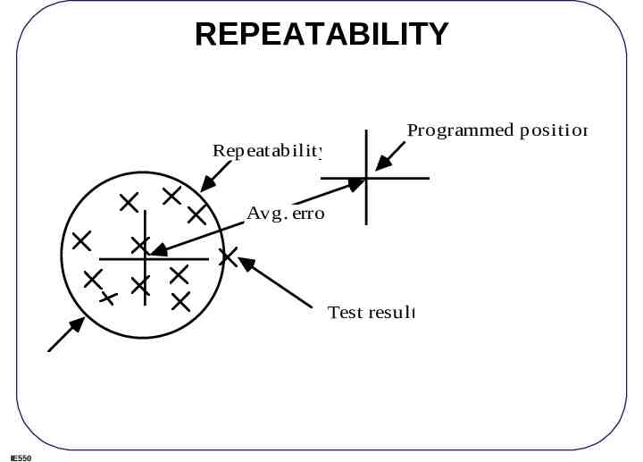
REPEATABILITY Repeatability Programmed position Avg. error Test result IE550
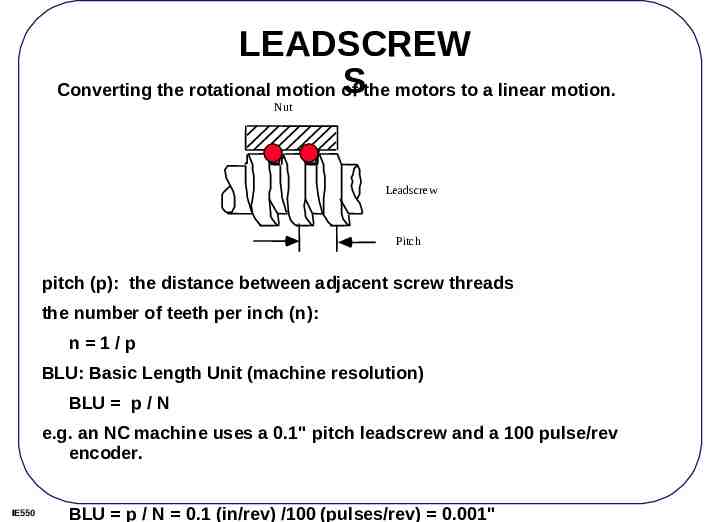
LEADSCREW Sthe motors to a linear motion. Converting the rotational motion of Nut Leadscrew Pitch pitch (p): the distance between adjacent screw threads the number of teeth per inch (n): n 1/p BLU: Basic Length Unit (machine resolution) BLU p / N e.g. an NC machine uses a 0.1" pitch leadscrew and a 100 pulse/rev encoder. IE550 BLU p / N 0.1 (in/rev) /100 (pulses/rev) 0.001"
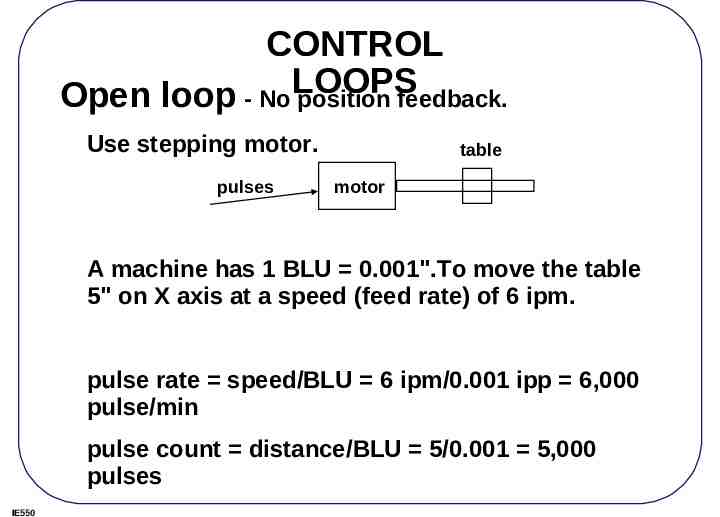
CONTROL LOOPS Open loop - No position feedback. Use stepping motor. pulses table motor A machine has 1 BLU 0.001".To move the table 5" on X axis at a speed (feed rate) of 6 ipm. pulse rate speed/BLU 6 ipm/0.001 ipp 6,000 pulse/min pulse count distance/BLU 5/0.001 5,000 pulses IE550
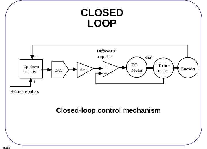
CLOSED LOOP Differential amplifier Up-down counter DAC Amp Shaft DC Motor Tachometer Reference pulses Closed-loop control mechanism IE550 Encoder
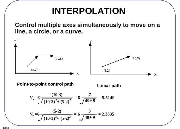
INTERPOLATION Control multiple axes simultaneously to move on a line, a circle, or a curve. Y Y (10,5) (10,5) (3,2) X Point-to-point control path Vx 6 Vy 6 IE550 (10-3) 2 (10-3) (5-2) 2 (5-2) 2 2 (10-3) (5-2) (3,2) X Linear path 6 7 5.5149 49 9 6 3 2.3635 49 9
INTERPOLATORS Most common interpolators are: linear and circular Since interpolation is right above the servo level, speed is critical, and the process must not involve excessive computation. Traditional NC interpolators: Digital Differential Analyzer (DDA) Higher order curves, such as Bezier's curve, use offline approximation algorithms to break the curves into linear or circular segments. IE550
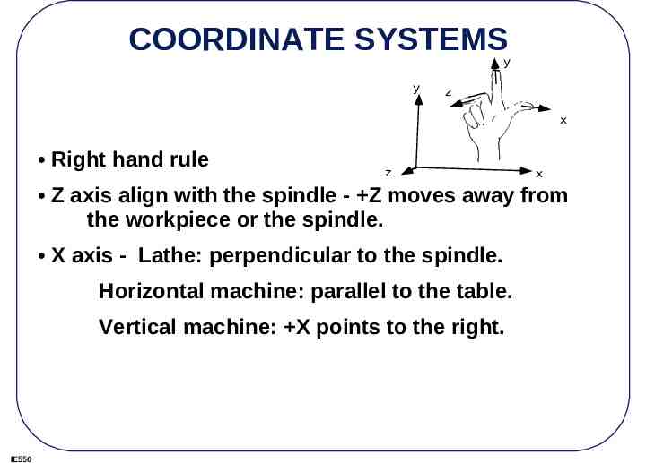
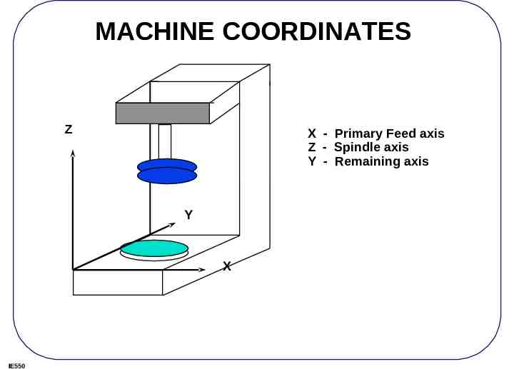
COORDINATE SYSTEMS y y z x Right hand rule z x Z axis align with the spindle - Z moves away from the workpiece or the spindle. X axis - Lathe: perpendicular to the spindle. Horizontal machine: parallel to the table. Vertical machine: X points to the right. IE550
MACHINE COORDINATES Z X - Primary Feed axis Z - Spindle axis Y - Remaining axis Y X IE550
Paper tape PROGRAM STORAGE Paper or Mylar coated paper. Diskettes From other computers through RS 232 or local area network (LAN) IE550
SYMBOLIC CODES ASCII or ISO, use even parity EIA - Binary Coded Decimal (BCD), RS 244A standard, use odd parity. IE550
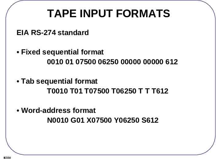
TAPE INPUT FORMATS EIA RS-274 standard Fixed sequential format 0010 01 07500 06250 00000 00000 612 Tab sequential format T0010 T01 T07500 T06250 T T T612 Word-address format N0010 G01 X07500 Y06250 S612 IE550
NC WORDS A G-code program consists the following words: N, G, X, Y, Z, A, B, C, I, J, K, F, S, T, R, M An EIA standard, RS-273 defines a set of standard codes. IE550
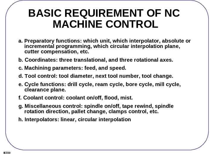
BASIC REQUIREMENT OF NC MACHINE CONTROL a. Preparatory functions: which unit, which interpolator, absolute or incremental programming, which circular interpolation plane, cutter compensation, etc. b. Coordinates: three translational, and three rotational axes. c. Machining parameters: feed, and speed. d. Tool control: tool diameter, next tool number, tool change. e. Cycle functions: drill cycle, ream cycle, bore cycle, mill cycle, clearance plane. f. Coolant control: coolant on/off, flood, mist. g. Miscellaneous control: spindle on/off, tape rewind, spindle rotation direction, pallet change, clamps control, etc. h. Interpolators: linear, circular interpolation IE550
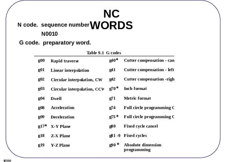
NC N code. sequence number WORDS N0010 G code. preparatory word. Table 9.1 G codes IE550 g00 Rapid traverse g40 * Cutter compensation - cancel g01 Linear interpolation g41 Cutter compensation - left g02 Circular interpolation, CW g42 Cutter compensation -right g03 Circular interpolation, CCW g70 * g04 Dwell g71 Metric format g08 Acceleration g74 Full circle programming Off g09 Deceleration g75 * Full circle programming On g17* X-Y Plane g80 Fixed cycle cancel g18 Z-X Plane g81 -9 Fixed cycles g19 Y-Z Plane g90 * g33 Thread cutting, constant lead g91 Inch format Absolute dimension programming Incremental deimension
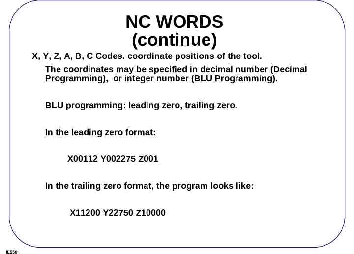
NC WORDS (continue) X, Y, Z, A, B, C Codes. coordinate positions of the tool. The coordinates may be specified in decimal number (Decimal Programming), or integer number (BLU Programming). BLU programming: leading zero, trailing zero. In the leading zero format: X00112 Y002275 Z001 In the trailing zero format, the program looks like: X11200 Y22750 Z10000 IE550
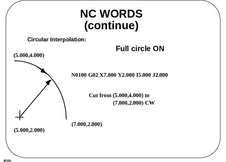
NC WORDS (continue) Circular Interpolation: Full circle ON (5.000,4.000) N0100 G02 X7.000 Y2.000 I5.000 J2.000 Cut from (5.000,4.000) to (7.000,2.000) CW (5.000,2.000) IE550 (7.000,2.000)
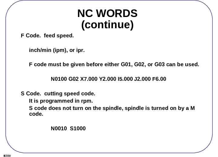
NC WORDS (continue) F Code. feed speed. inch/min (ipm), or ipr. F code must be given before either G01, G02, or G03 can be used. N0100 G02 X7.000 Y2.000 I5.000 J2.000 F6.00 S Code. cutting speed code. It is programmed in rpm. S code does not turn on the spindle, spindle is turned on by a M code. N0010 S1000 IE550
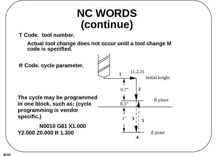
NC WORDS (continue) T Code. tool number. Actual tool change does not occur until a tool change M code is specified. R Code. cycle parameter. (1,2,2) 1 Initial height 2 0.7" The cycle may be programmed in one block, such as: (cycle programming is vendor specific.) N0010 G81 X1.000 Y2.000 Z0.000 R 1.300 IE550 R plane 0.3" 1" 3 5 4 Z point
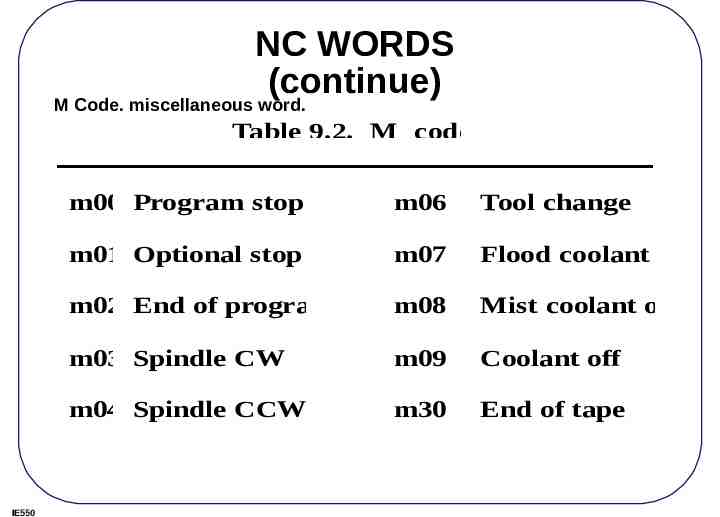
NC WORDS (continue) M Code. miscellaneous word. Table 9.2. M codes m00 Program stop m06 Tool change m01 Optional stop m07 Flood coolant on m02 End of program m08 Mist coolant on m03 Spindle CW m09 Coolant off m04 Spindle CCW m30 End of tape m05 Spindle off IE550
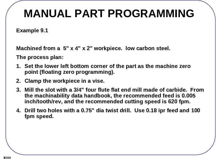
MANUAL PART PROGRAMMING Example 9.1 Machined from a 5" x 4" x 2" workpiece. low carbon steel. The process plan: 1. Set the lower left bottom corner of the part as the machine zero point (floating zero programming). 2. Clamp the workpiece in a vise. 3. Mill the slot with a 3/4" four flute flat end mill made of carbide. From the machinability data handbook, the recommended feed is 0.005 inch/tooth/rev, and the recommended cutting speed is 620 fpm. 4. Drill two holes with a 0.75" dia twist drill. Use 0.18 ipr feed and 100 fpm speed. IE550
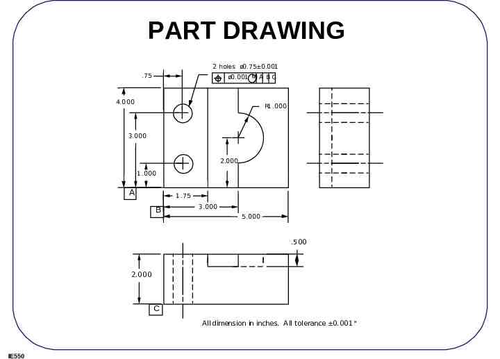
PART DRAWING 2 holes ø0.75 0.001 .75 ø0.001 M MA BC 4.000 R1 .000 3.000 2.000 1 .000 A 1 .75 B 3.000 5.000 .500 2.000 C All dimension in inches. A ll tolerance 0.001" IE550
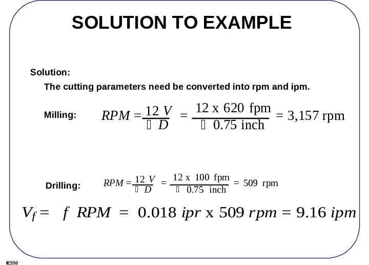
SOLUTION TO EXAMPLE Solution: The cutting parameters need be converted into rpm and ipm. Milling: 12 x 620 fpm 12 V RPM 3,157 rpm D 0.75 inch Drilling: 12 x 100 fpm RPM 12 V 509 rpm D 0.75 inch Vf f RPM 0.018 ipr x 509 rpm 9.16 ipm IE550
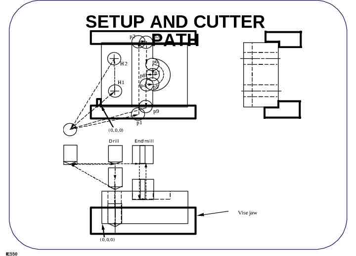
SETUP AND CUTTER PATH p2 p3 p6 H2 p7 p8 H1 p4 p5 p9 p1 (0,0,0) Drill End mill Vise jaw (0,0,0) IE550
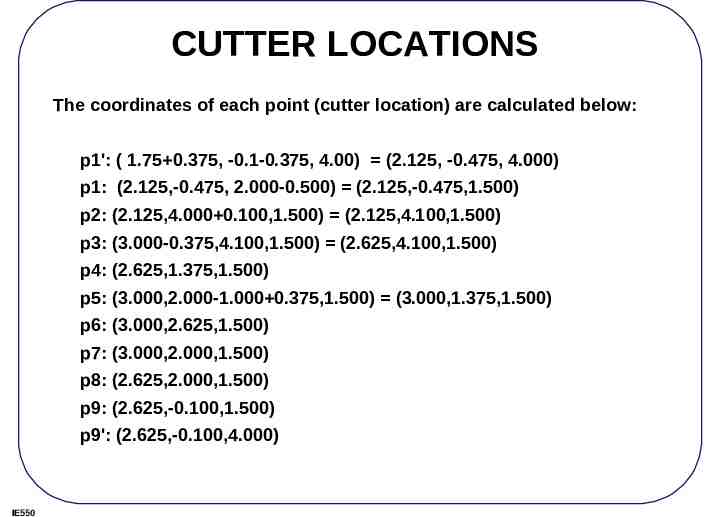
CUTTER LOCATIONS The coordinates of each point (cutter location) are calculated below: p1': ( 1.75 0.375, -0.1-0.375, 4.00) (2.125, -0.475, 4.000) p1: (2.125,-0.475, 2.000-0.500) (2.125,-0.475,1.500) p2: (2.125,4.000 0.100,1.500) (2.125,4.100,1.500) p3: (3.000-0.375,4.100,1.500) (2.625,4.100,1.500) p4: (2.625,1.375,1.500) p5: (3.000,2.000-1.000 0.375,1.500) (3.000,1.375,1.500) p6: (3.000,2.625,1.500) p7: (3.000,2.000,1.500) p8: (2.625,2.000,1.500) p9: (2.625,-0.100,1.500) p9': (2.625,-0.100,4.000) IE550
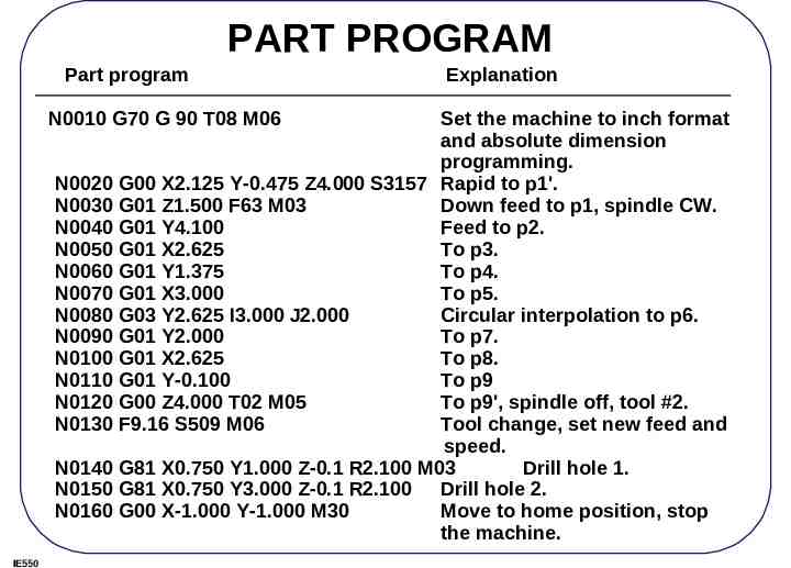
PART PROGRAM Part program N0010 G70 G 90 T08 M06 Explanation Set the machine to inch format and absolute dimension programming. N0020 G00 X2.125 Y-0.475 Z4.000 S3157 Rapid to p1'. N0030 G01 Z1.500 F63 M03 Down feed to p1, spindle CW. N0040 G01 Y4.100 Feed to p2. N0050 G01 X2.625 To p3. N0060 G01 Y1.375 To p4. N0070 G01 X3.000 To p5. N0080 G03 Y2.625 I3.000 J2.000 Circular interpolation to p6. N0090 G01 Y2.000 To p7. N0100 G01 X2.625 To p8. N0110 G01 Y-0.100 To p9 N0120 G00 Z4.000 T02 M05 To p9', spindle off, tool #2. N0130 F9.16 S509 M06 Tool change, set new feed and speed. N0140 G81 X0.750 Y1.000 Z-0.1 R2.100 M03 Drill hole 1. N0150 G81 X0.750 Y3.000 Z-0.1 R2.100 Drill hole 2. N0160 G00 X-1.000 Y-1.000 M30 Move to home position, stop the machine. IE550
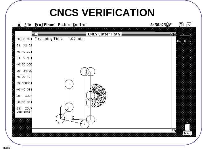
CNCS VERIFICATION IE550
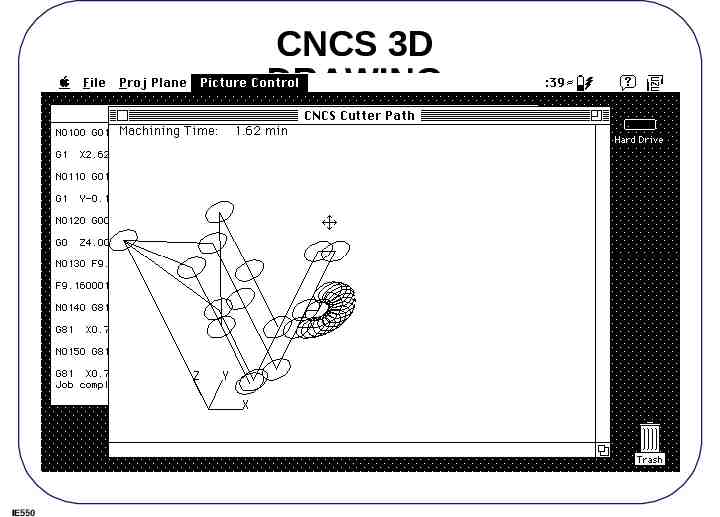
CNCS 3D DRAWING IE550
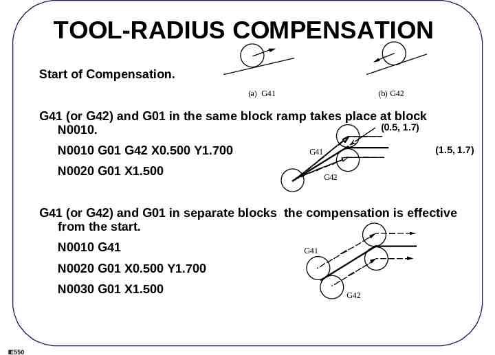
TOOL-RADIUS COMPENSATION Start of Compensation. (a) G41 (b) G42 G41 (or G42) and G01 in the same block ramp takes place at block (0.5, 1.7) N0010. N0010 G01 G42 X0.500 Y1.700 (1.5, 1.7) G41 N0020 G01 X1.500 G42 G41 (or G42) and G01 in separate blocks the compensation is effective from the start. N0010 G41 G41 N0020 G01 X0.500 Y1.700 N0030 G01 X1.500 IE550 G42
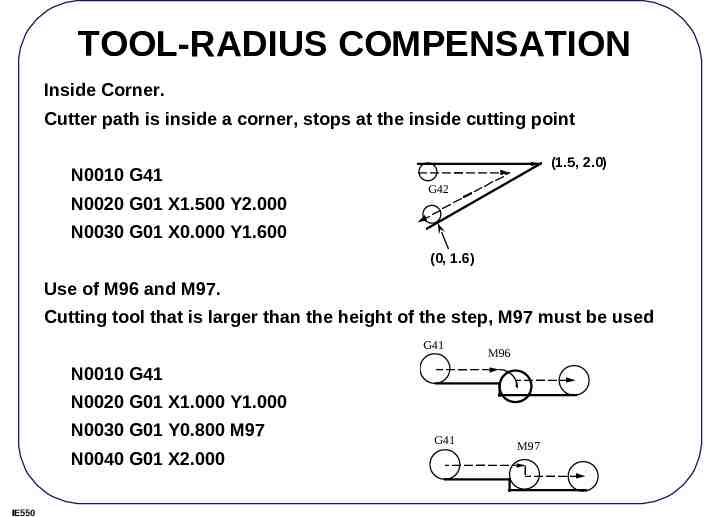
TOOL-RADIUS COMPENSATION Inside Corner. Cutter path is inside a corner, stops at the inside cutting point N0010 G41 N0020 G01 X1.500 Y2.000 (1.5, 2.0) G42 N0030 G01 X0.000 Y1.600 (0, 1.6) Use of M96 and M97. Cutting tool that is larger than the height of the step, M97 must be used G41 M96 N0010 G41 N0020 G01 X1.000 Y1.000 N0030 G01 Y0.800 M97 N0040 G01 X2.000 IE550 G41 M97
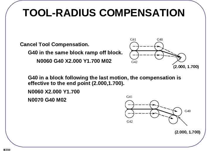
TOOL-RADIUS COMPENSATION G41 G40 Cancel Tool Compensation. G40 in the same block ramp off block. N0060 G40 X2.000 Y1.700 M02 G42 (2.000, 1.700) G40 in a block following the last motion, the compensation is effective to the end point (2.000,1.700). N0060 X2.000 Y1.700 N0070 G40 M02 G41 G40 G42 (2.000, 1.700) IE550
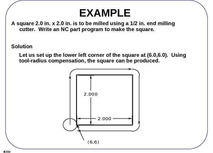
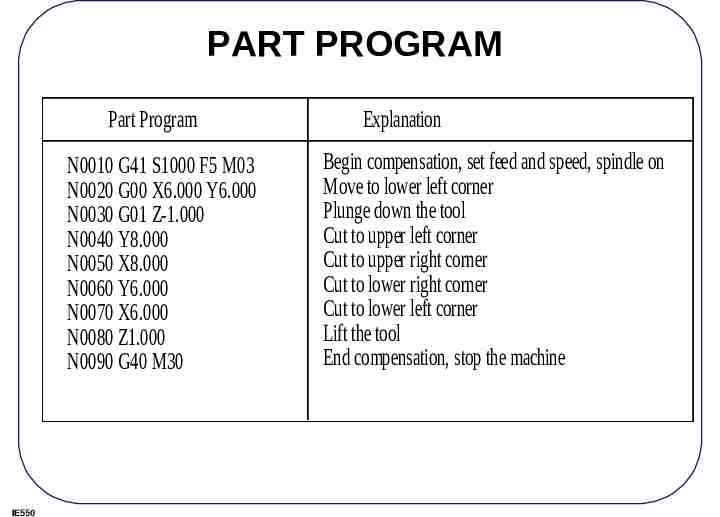
EXAMPLE A square 2.0 in. x 2.0 in. is to be milled using a 1/2 in. end milling cutter. Write an NC part program to make the square. Solution Let us set up the lower left corner of the square at (6.0,6.0). Using tool-radius compensation, the square can be produced. 2.000 2.000 (6,6) IE550
PART PROGRAM Part Program N0010 G41 S1000 F5 M03 N0020 G00 X6.000 Y6.000 N0030 G01 Z-1.000 N0040 Y8.000 N0050 X8.000 N0060 Y6.000 N0070 X6.000 N0080 Z1.000 N0090 G40 M30 IE550 Explanation Begin compensation, set feed and speed, spindle on Move to lower left corner Plunge down the tool Cut to upper left corner Cut to upper right corner Cut to lower right corner Cut to lower left corner Lift the tool End compensation, stop the machine
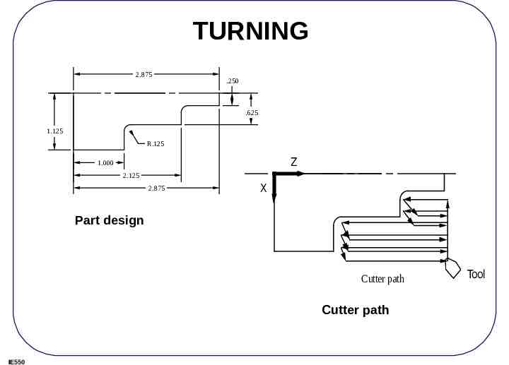
TURNING 2.875 .250 .625 1.125 R.125 Z 1.000 2.125 2.875 X Part design Cutter path Cutter path IE550 Tool
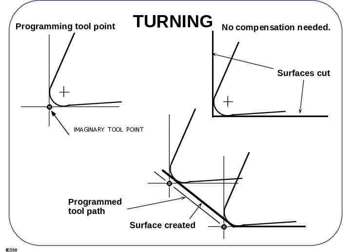
Programming tool point TURNING No compensation needed. Surfaces cut IMAGINARY TOOL POINT Programmed tool path Surface created IE550
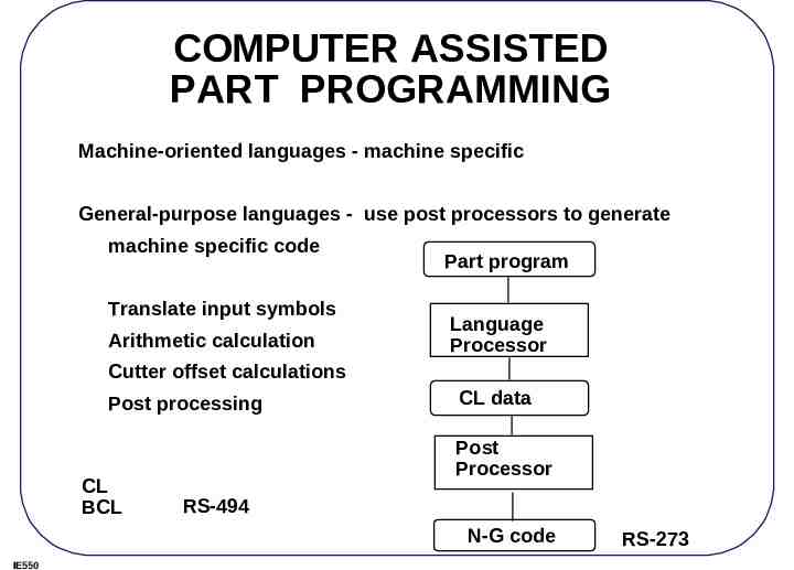
COMPUTER ASSISTED PART PROGRAMMING Machine-oriented languages - machine specific General-purpose languages - use post processors to generate machine specific code Translate input symbols Arithmetic calculation Part program Language Processor Cutter offset calculations Post processing CL BCL CL data Post Processor RS-494 N-G code IE550 RS-273