ER to Relational Mapping Sampath Jayarathna Cal Poly Pomona
61 Slides1.95 MB
ER to Relational Mapping Sampath Jayarathna Cal Poly Pomona
Relational Data Model Basic Concepts: relational data model, relation schema, domain, tuple, cardinality & degree, database schema, etc. Relational Integrity Constraints key, primary key & foreign key entity integrity constraint referential integrity Update Operations on Relations ER/EER to Relational Mapping 2
Basic Concepts The relational model of data is based on the concept of a relation A relation is a mathematical concept based on the ideas of sets The model was first proposed by Dr. E.F. Codd of IBM in 1970 in the following paper: "A Relational Model for Large Shared Data Banks," Communications of the ACM, June 1970 3
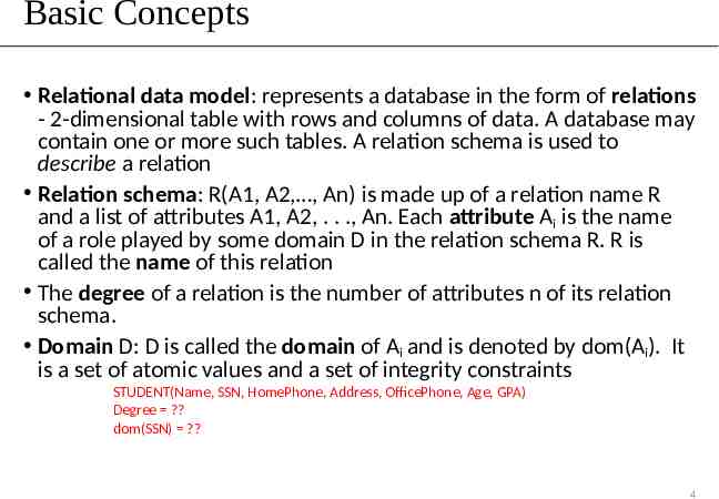
Basic Concepts Relational data model: represents a database in the form of relations - 2-dimensional table with rows and columns of data. A database may contain one or more such tables. A relation schema is used to describe a relation Relation schema: R(A1, A2, , An) is made up of a relation name R and a list of attributes A1, A2, . . ., An. Each attribute Ai is the name of a role played by some domain D in the relation schema R. R is called the name of this relation The degree of a relation is the number of attributes n of its relation schema. Domain D: D is called the domain of Ai and is denoted by dom(Ai). It is a set of atomic values and a set of integrity constraints STUDENT(Name, SSN, HomePhone, Address, OfficePhone, Age, GPA) Degree ? dom(SSN) ? 4
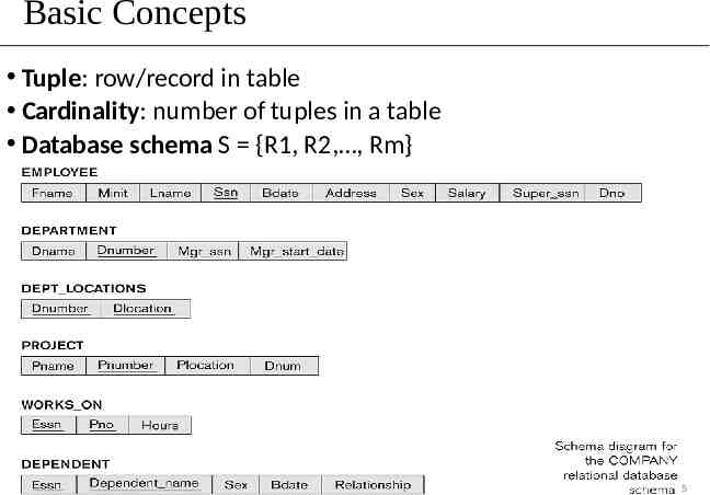
Basic Concepts Tuple: row/record in table Cardinality: number of tuples in a table Database schema S {R1, R2, , Rm} 5
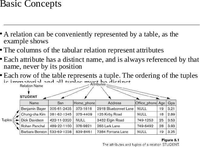
Basic Concepts A relation can be conveniently represented by a table, as the example shows The columns of the tabular relation represent attributes Each attribute has a distinct name, and is always referenced by that name, never by its position Each row of the table represents a tuple. The ordering of the tuples is immaterial and all tuples must be distinct
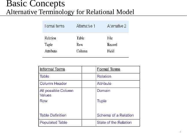
Basic Concepts Alternative Terminology for Relational Model 7
Relational Integrity Constraints Constraints are conditions that must hold on all valid relation instances. There are three main types of constraints: Key constraints Entity integrity constraints Referential integrity constraints 8
Key Constraints Key of a Relation: Each row has a value of a data item (or set of items) that uniquely identifies that row in the table Called the key In the STUDENT table, SSN is the key Sometimes row-ids or sequential numbers are assigned as keys to identify the rows in a table Called artificial key or surrogate key 9
Key Constraints (continued) If a relation has several candidate keys, one is chosen arbitrarily to be the primary key. The primary key attributes are underlined. Example: Consider the CAR relation schema: CAR(State, Reg#, SerialNo, Make, Model, Year) We chose SerialNo as the primary key The primary key value is used to uniquely identify each tuple in a relation Provides the tuple identity Also used to reference the tuple from another tuple General rule: Choose as primary key the smallest of the candidate keys (in terms of size) Not always applicable – choice is sometimes subjective 10
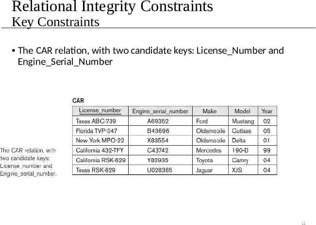
Relational Integrity Constraints Key Constraints The CAR relation, with two candidate keys: License Number and Engine Serial Number 11
Relational Integrity Constraints Entity Integrity: The primary key attributes PK of each relation schema R in S cannot have null values in any tuple of r(R). This is because primary key values are used to identify the individual tuples. t[PK] null for any tuple t in r(R) If PK has several attributes, null is not allowed in any of these attributes Note: Other attributes of R may be constrained to disallow null values, even though they are not members of the primary key. 12
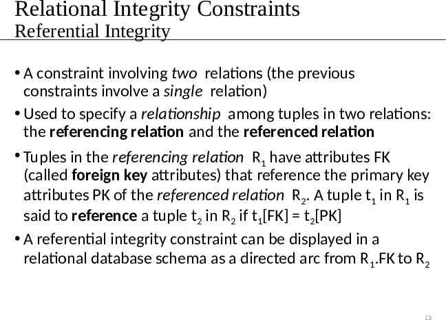
Relational Integrity Constraints Referential Integrity A constraint involving two relations (the previous constraints involve a single relation) Used to specify a relationship among tuples in two relations: the referencing relation and the referenced relation Tuples in the referencing relation R1 have attributes FK (called foreign key attributes) that reference the primary key attributes PK of the referenced relation R2. A tuple t1 in R1 is said to reference a tuple t2 in R2 if t1[FK] t2[PK] A referential integrity constraint can be displayed in a relational database schema as a directed arc from R1.FK to R2 13
Relational Integrity Constraints Referential Integrity Statement of the constraint The value in the foreign key column (or columns) FK of the the referencing relation R1 can be either: (1) a value of an existing primary key value of the corresponding primary key PK in the referenced relation R2,, or (2) a NULL In case (2), the FK in R1 should not be a part of its own primary key 14
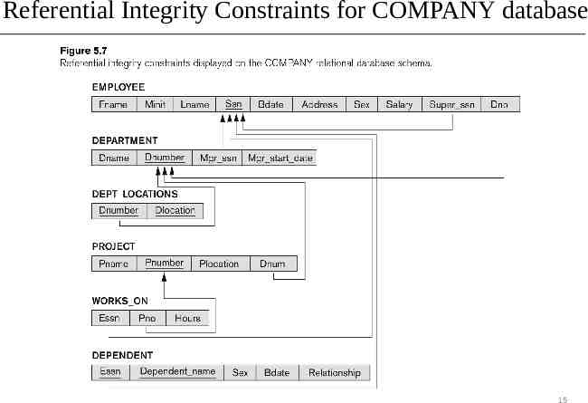
Referential Integrity Constraints for COMPANY database 15
Relational Data Model Basic Concepts: relational data model, relation schema, domain, tuple, cardinality & degree, database schema, etc. Relational Integrity Constraints key, primary key & foreign key entity integrity constraint referential integrity Update Operations on Relations 16
Update Operations on Relations INSERT a tuple DELETE a tuple MODIFY a tuple Integrity constraints should not be violated by the update operations 17
Update Operations on Relations INSERT may violate any of the constraints: Domain constraint: if one of the attribute values provided for the new tuple is not of the specified attribute domain Key constraint: if the value of a key attribute in the new tuple already exists in another tuple in the relation Referential integrity: if a foreign key value in the new tuple references a primary key value that does not exist in the referenced relation Entity integrity: if the primary key value is null in the new tuple 18
Update Operations on Relations DELETE may violate only referential integrity: If the primary key value of the tuple being deleted is referenced from other tuples in the database Can be remedied by several actions: RESTRICT, CASCADE, SET NULL RESTRICT option: reject the deletion CASCADE option: propagate the new primary key value into the foreign keys of the referencing tuples SET NULL option: set the foreign keys of the referencing tuples to NULL One of the above options must be specified during database design for each foreign key constraint 19
Update Operations on Relations In case of integrity violation, several actions can be taken: Cancel the operation that causes the violation (RESTRICT or REJECT option) Perform the operation but inform the user of the violation Trigger additional updates so the violation is corrected (CASCADE option, SET NULL option) Execute a user-specified error-correction routine 20
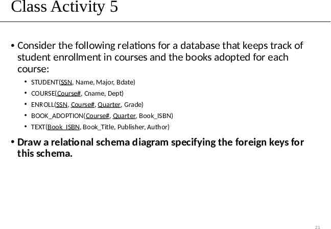
Class Activity 5 Consider the following relations for a database that keeps track of student enrollment in courses and the books adopted for each course: STUDENT(SSN, Name, Major, Bdate) COURSE(Course#, Cname, Dept) ENROLL(SSN, Course#, Quarter, Grade) BOOK ADOPTION(Course#, Quarter, Book ISBN) TEXT(Book ISBN, Book Title, Publisher, Author) Draw a relational schema diagram specifying the foreign keys for this schema. 21
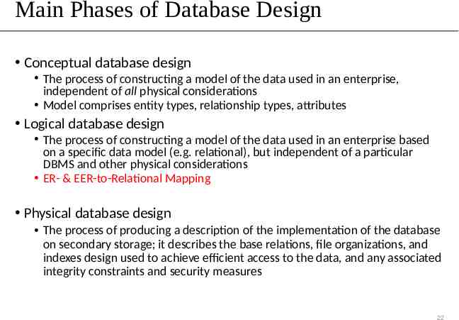
Main Phases of Database Design Conceptual database design The process of constructing a model of the data used in an enterprise, independent of all physical considerations Model comprises entity types, relationship types, attributes Logical database design The process of constructing a model of the data used in an enterprise based on a specific data model (e.g. relational), but independent of a particular DBMS and other physical considerations ER- & EER-to-Relational Mapping Physical database design The process of producing a description of the implementation of the database on secondary storage; it describes the base relations, file organizations, and indexes design used to achieve efficient access to the data, and any associated integrity constraints and security measures 22
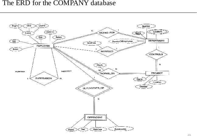
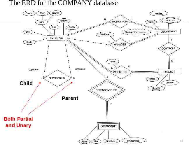
The ERD for the COMPANY database 23
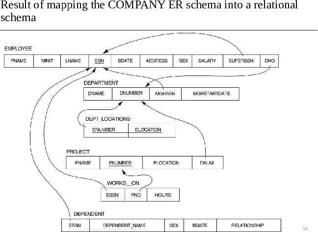
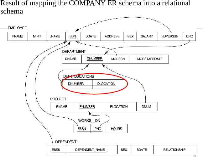
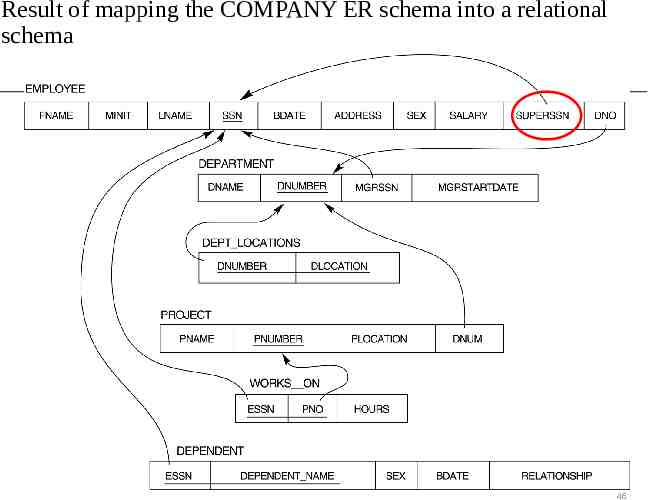
Result of mapping the COMPANY ER schema into a relational schema 24
ER- & EER-to-Relational Mapping ER Step 1: Mapping of Regular Entity Types Step 2: Mapping of Weak Entity Types Step 3: Mapping of Binary 1:1 Relationship Types Step 4: Mapping of Binary 1:N Relationship Types Step 5: Mapping of Binary M:N Relationship Types Step 6: Mapping of Multivalued attributes Step 7: Mapping of N-ary Relationship Types EER Step 8: Options for Mapping Specialization or Generalization. Step 9: Mapping of Union Types (Categories) 25
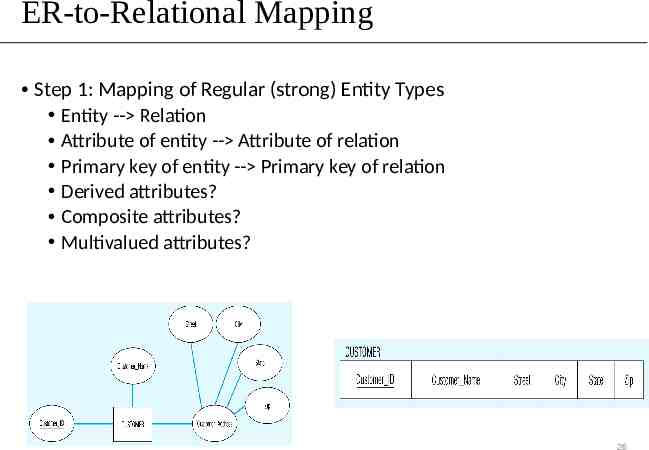
ER-to-Relational Mapping Step 1: Mapping of Regular (strong) Entity Types Entity -- Relation Attribute of entity -- Attribute of relation Primary key of entity -- Primary key of relation Derived attributes? Composite attributes? Multivalued attributes? 26
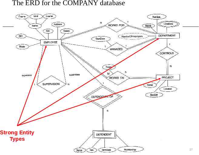
The ERD for the COMPANY database Strong Entity Types 27
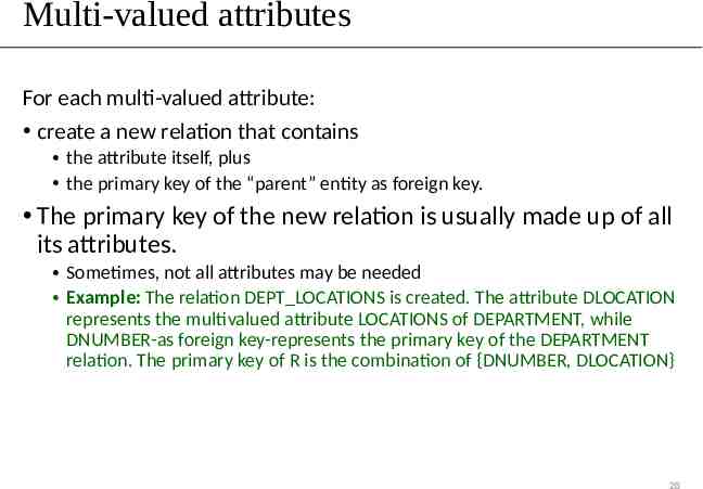
Multi-valued attributes For each multi-valued attribute: create a new relation that contains the attribute itself, plus the primary key of the “parent” entity as foreign key. The primary key of the new relation is usually made up of all its attributes. Sometimes, not all attributes may be needed Example: The relation DEPT LOCATIONS is created. The attribute DLOCATION represents the multivalued attribute LOCATIONS of DEPARTMENT, while DNUMBER-as foreign key-represents the primary key of the DEPARTMENT relation. The primary key of R is the combination of {DNUMBER, DLOCATION} 28
Result of mapping the COMPANY ER schema into a relational schema 29
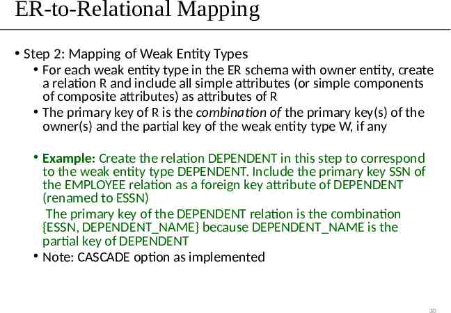
ER-to-Relational Mapping Step 2: Mapping of Weak Entity Types For each weak entity type in the ER schema with owner entity, create a relation R and include all simple attributes (or simple components of composite attributes) as attributes of R The primary key of R is the combination of the primary key(s) of the owner(s) and the partial key of the weak entity type W, if any Example: Create the relation DEPENDENT in this step to correspond to the weak entity type DEPENDENT. Include the primary key SSN of the EMPLOYEE relation as a foreign key attribute of DEPENDENT (renamed to ESSN) The primary key of the DEPENDENT relation is the combination {ESSN, DEPENDENT NAME} because DEPENDENT NAME is the partial key of DEPENDENT Note: CASCADE option as implemented 30
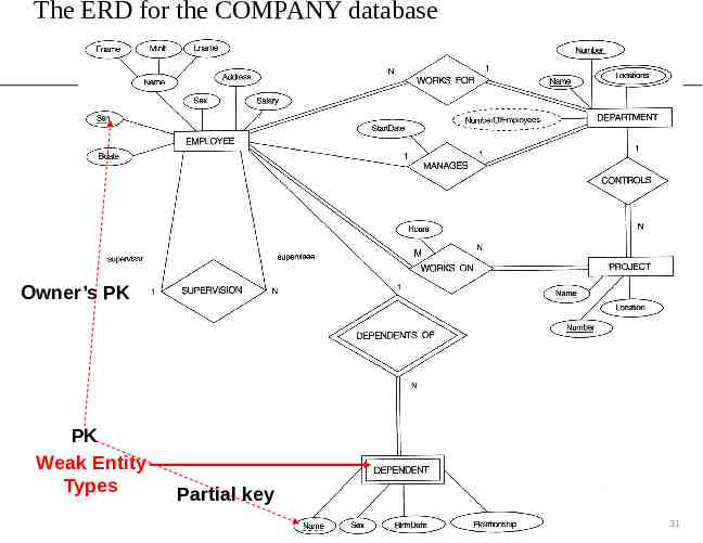
The ERD for the COMPANY database Owner’s PK PK Weak Entity Types Partial key 31
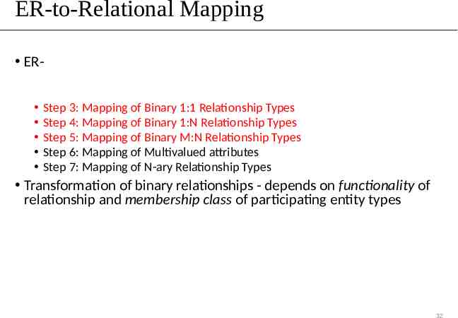
ER-to-Relational Mapping ER Step 1: Mapping of Regular Entity Types Step 2: Mapping of Weak Entity Types Step 3: Mapping of Binary 1:1 Relationship Types Step 4: Mapping of Binary 1:N Relationship Types Step 5: Mapping of Binary M:N Relationship Types Step 6: Mapping of Multivalued attributes Step 7: Mapping of N-ary Relationship Types Transformation of binary relationships - depends on functionality of relationship and membership class of participating entity types 32
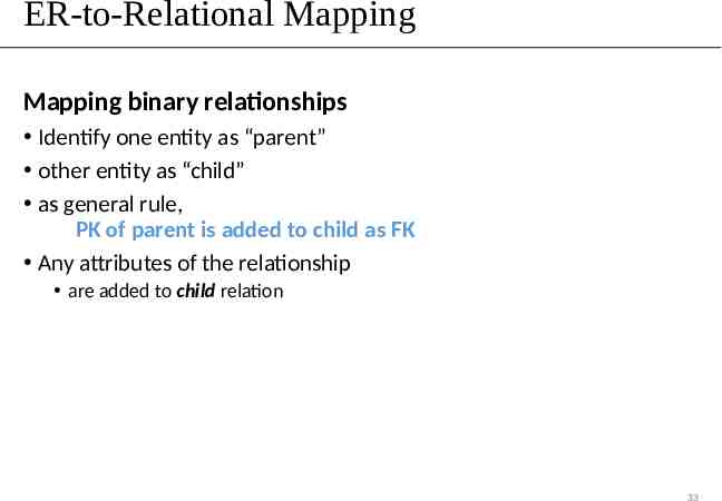
ER-to-Relational Mapping Mapping binary relationships Identify one entity as “parent” other entity as “child” as general rule, PK of parent is added to child as FK Any attributes of the relationship are added to child relation 33
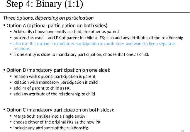
Step 4: Binary (1:1) Three options, depending on participation Option A (optional participation on both sides) Arbitrarily choose one entity as child, the other as parent proceed as usual - add PK of parent to child as FK; also add any attributes of the relationship also use this option if mandatory participation on both sides and want to keep separate relations If one entity is close to mandatory participation, choose that one as child. Option B (mandatory participation on one side): relation with optional participation is parent Relation with mandatory participation is child add PK of parent to child as FK. add any attribute of the relationship to child Option C (mandatory participation on both sides): Merge both entities into a single entity choose either of the original PKs as the new PK include any attributes of the relationship 34
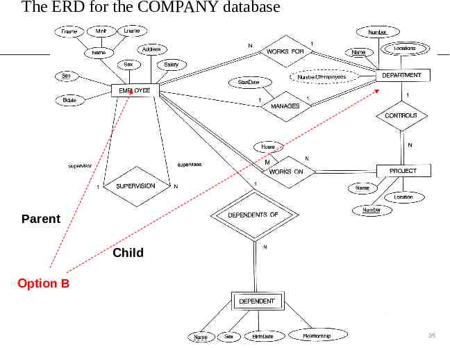
The ERD for the COMPANY database Parent Child Option B 35
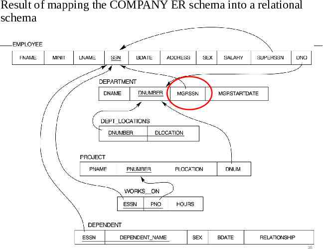
Result of mapping the COMPANY ER schema into a relational schema 36
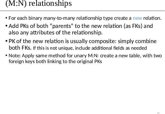
(M:N) relationships For each binary many-to-many relationship type create a new relation. Add PKs of both “parents” to the new relation (as FKs) and also any attributes of the relationship. PK of the new relation is usually composite: simply combine both FKs. If this is not unique, include additional fields as needed Note: Apply same method for unary M:N: create a new table, with two foreign keys both linking to the original PKs 37
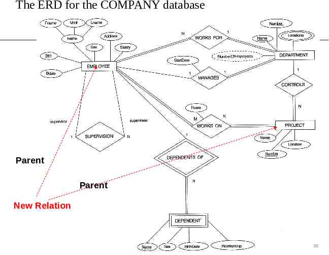
The ERD for the COMPANY database Parent Parent New Relation 38
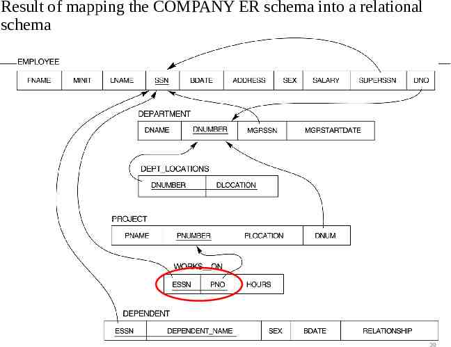
Result of mapping the COMPANY ER schema into a relational schema 39
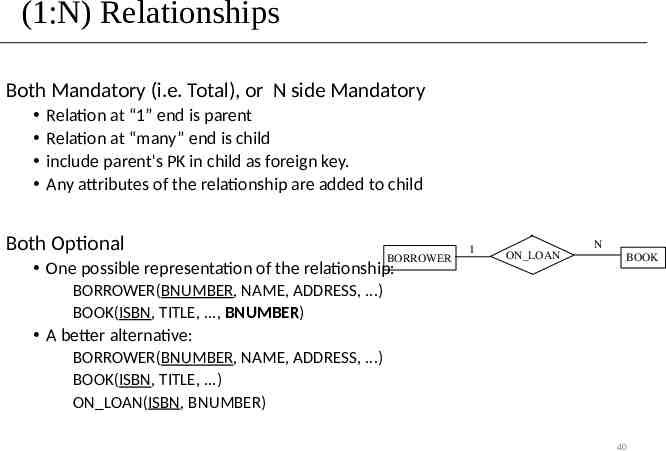
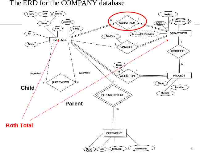
(1:N) Relationships Both Mandatory (i.e. Total), or N side Mandatory Relation at “1” end is parent Relation at “many” end is child include parent's PK in child as foreign key. Any attributes of the relationship are added to child Both Optional BORROWER One possible representation of the relationship: 1 ON LOAN N BOOK BORROWER(BNUMBER, NAME, ADDRESS, .) BOOK(ISBN, TITLE, ., BNUMBER) A better alternative: BORROWER(BNUMBER, NAME, ADDRESS, .) BOOK(ISBN, TITLE, .) ON LOAN(ISBN, BNUMBER) 40
The ERD for the COMPANY database Child Parent Both Total 41
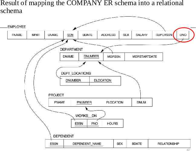
Result of mapping the COMPANY ER schema into a relational schema 42
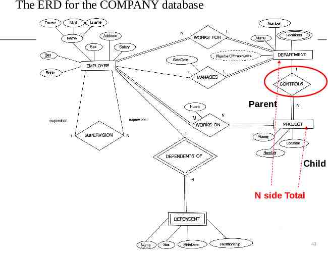
The ERD for the COMPANY database Parent Child N side Total 43
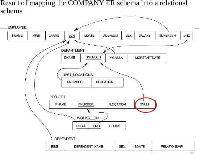
Result of mapping the COMPANY ER schema into a relational schema 44
The ERD for the COMPANY database Child Parent Both Partial and Unary 45
Result of mapping the COMPANY ER schema into a relational schema 46
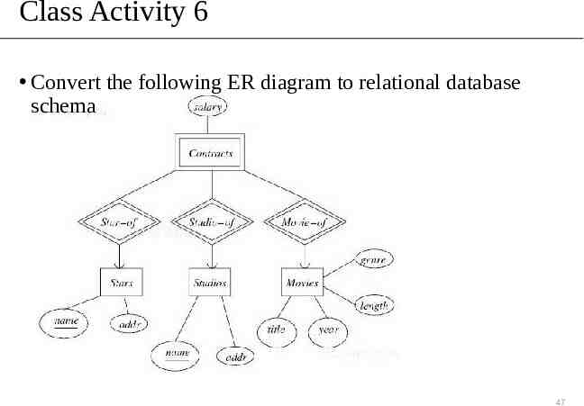
Class Activity 6 Convert the following ER diagram to relational database schema 47
ER-to-Relational Mapping ER Step 1: Mapping of Regular Entity Types Step 2: Mapping of Weak Entity Types Step 3: Mapping of Binary 1:1 Relationship Types Step 4: Mapping of Binary 1:N Relationship Types Step 5: Mapping of Binary M:N Relationship Types Step 6: Mapping of Multivalued attributes Step 7: Mapping of N-ary Relationship Types 48
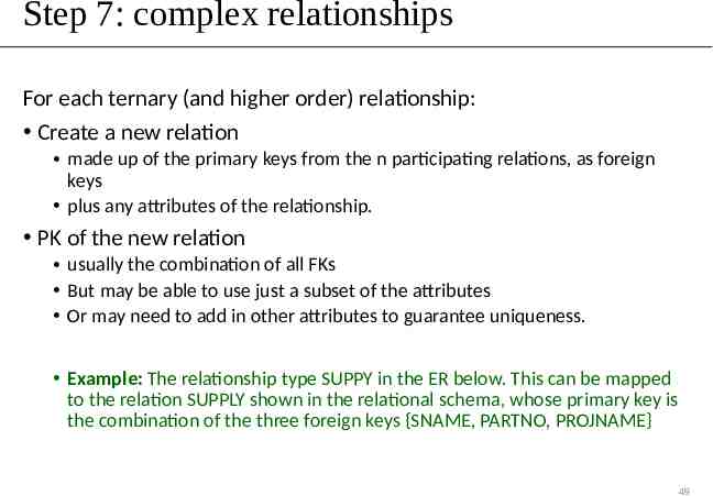
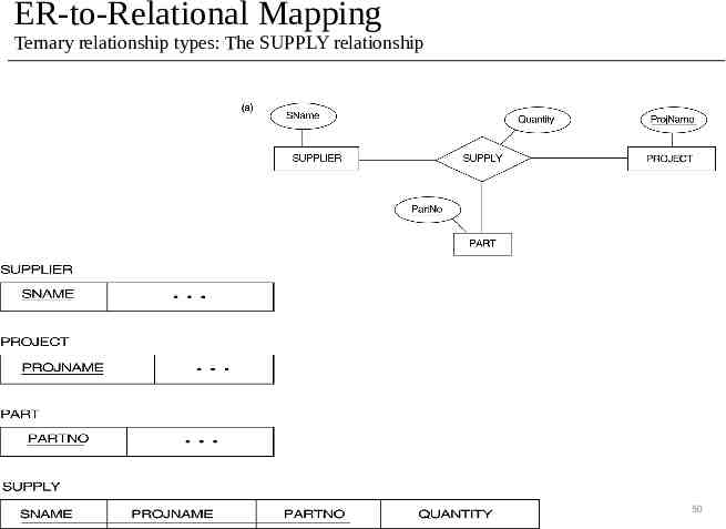
Step 7: complex relationships For each ternary (and higher order) relationship: Create a new relation made up of the primary keys from the n participating relations, as foreign keys plus any attributes of the relationship. PK of the new relation usually the combination of all FKs But may be able to use just a subset of the attributes Or may need to add in other attributes to guarantee uniqueness. Example: The relationship type SUPPY in the ER below. This can be mapped to the relation SUPPLY shown in the relational schema, whose primary key is the combination of the three foreign keys {SNAME, PARTNO, PROJNAME} 49
ER-to-Relational Mapping Ternary relationship types: The SUPPLY relationship 50
ER- & EER-to-Relational Mapping ER Step 1: Mapping of Regular Entity Types Step 2: Mapping of Weak Entity Types Step 3: Mapping of Binary 1:1 Relationship Types Step 4: Mapping of Binary 1:N Relationship Types Step 5: Mapping of Binary M:N Relationship Types Step 6: Mapping of Multivalued attributes Step 7: Mapping of N-ary Relationship Types EER Step 8: Options for Mapping Specialization or Generalization. Step 9: Mapping of Union Types (Categories) 51
EER-to-Relational Mapping Step8: Options for Mapping Specialization or Generalization. Convert each specialization with m subclasses {S1, S2, .,Sm} and generalized superclass C, where the attributes of C are {k,a1, an} and k is the (primary) key, into relational schemas using one of the four following options: Option 8A: Multiple relations-Superclass and subclasses Option 8B: Multiple relations-Subclass relations only Option 8C: Single relation with one type attribute Option 8D: Single relation with multiple type attributes 52 52
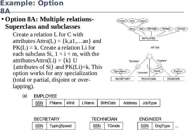
Example: Option 8A Option 8A: Multiple relationsSuperclass and subclasses Create a relation L for C with attributes Attrs(L) {k,a1, an} and PK(L) k. Create a relation Li for each subclass Si, 1 i m, with the attributesAttrs(Li) {k} U {attributes of Si} and PK(Li) k. This option works for any specialization (total or partial, disjoint or overlapping). 53
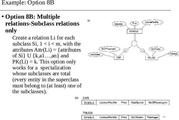
Example: Option 8B Option 8B: Multiple relations-Subclass relations only Create a relation Li for each subclass Si, 1 i m, with the attributes Attr(Li) {attributes of Si} U {k,a1 ,an} and PK(Li) k. This option only works for a specialization whose subclasses are total (every entity in the superclass must belong to (at least) one of the subclasses). Tonnage 54
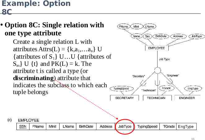
Example: Option 8C Option 8C: Single relation with one type attribute Create a single relation L with attributes Attrs(L) {k,a1, an} U {attributes of S1} U U {attributes of Sm} U {t} and PK(L) k. The attribute t is called a type (or discriminating) attribute that indicates the subclass to which each tuple belongs EngType 55
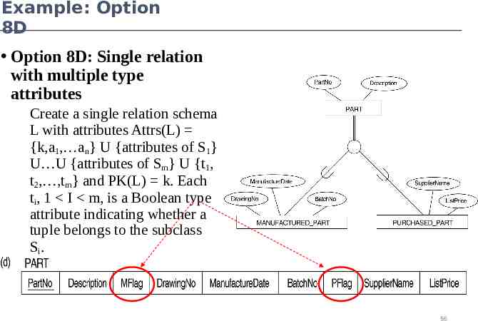
Example: Option 8D Option 8D: Single relation with multiple type attributes Create a single relation schema L with attributes Attrs(L) {k,a1, an} U {attributes of S1} U U {attributes of Sm} U {t1, t2, ,tm} and PK(L) k. Each ti, 1 I m, is a Boolean type attribute indicating whether a tuple belongs to the subclass Si. 56
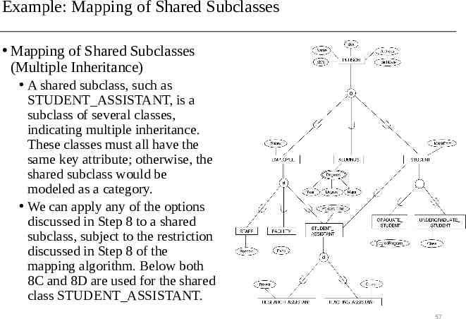
Example: Mapping of Shared Subclasses Mapping of Shared Subclasses (Multiple Inheritance) A shared subclass, such as STUDENT ASSISTANT, is a subclass of several classes, indicating multiple inheritance. These classes must all have the same key attribute; otherwise, the shared subclass would be modeled as a category. We can apply any of the options discussed in Step 8 to a shared subclass, subject to the restriction discussed in Step 8 of the mapping algorithm. Below both 8C and 8D are used for the shared class STUDENT ASSISTANT. 57
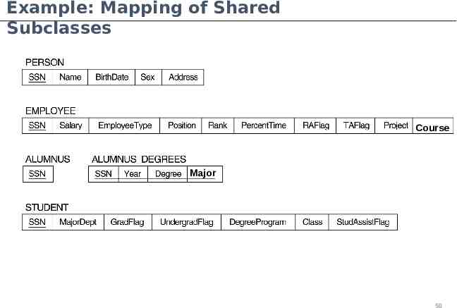
Example: Mapping of Shared Subclasses Course Major 58
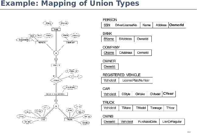
EER-to-Relational Mapping Step 9: Mapping of Union Types (Categories). For mapping a category whose defining superclass have different keys, it is customary to specify a new key attribute, called a surrogate key, when creating a relation to correspond to the category. In the example below we can create a relation OWNER to correspond to the OWNER category and include any attributes of the category in this relation. The primary key of the OWNER relation is the surrogate key, which we called OwnerId. 59
Example: Mapping of Union Types OwnerId CYear 60
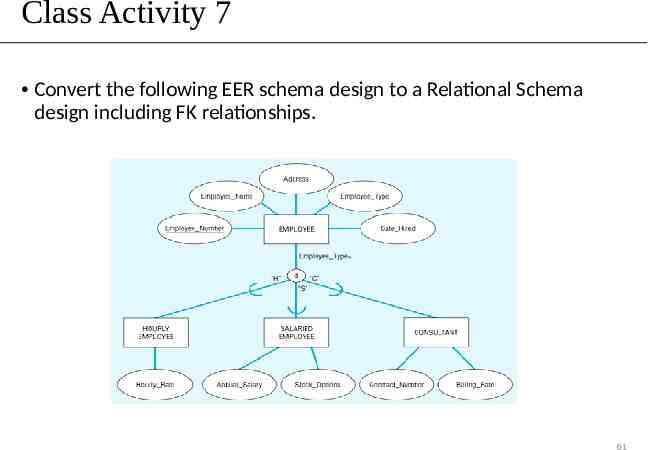
Class Activity 7 Convert the following EER schema design to a Relational Schema design including FK relationships. 61