ENERGY CONVERSION MME 9617A Eric Savory


52 Slides1.02 MB
ENERGY CONVERSION MME 9617A Eric Savory www.eng.uwo.ca/people/esavory/ mme9617a.htm Lecture 8 – Basics of heat exchangers Department of Mechanical and Material Engineering University of Western Ontario
Heat Exchangers The most common types of energy conversion systems (e.g. internal combustion engines, gas/steam turbines, boilers) consist of three parts: 1. a combustion process generating heat and energy (K.E.) 2. a device for converting K.E. to mechanical (useful) energy 3. heat exchangers to recuperate the heat either for heating purposes or to increase efficiency. kinetic
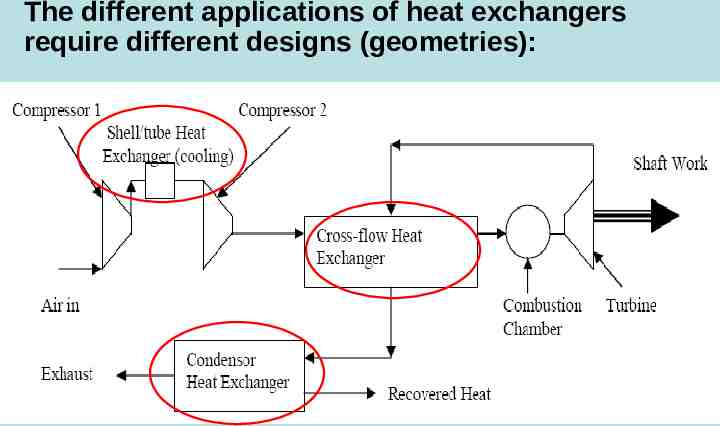
The different applications of heat exchangers require different designs (geometries):
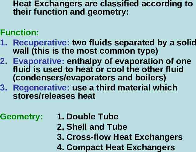
Heat Exchangers are classified according to their function and geometry: Function: 1. Recuperative: two fluids separated by a solid wall (this is the most common type) 2. Evaporative: enthalpy of evaporation of one fluid is used to heat or cool the other fluid (condensers/evaporators and boilers) 3. Regenerative: use a third material which stores/releases heat Geometry: 1. Double Tube 2. Shell and Tube 3. Cross-flow Heat Exchangers 4. Compact Heat Exchangers
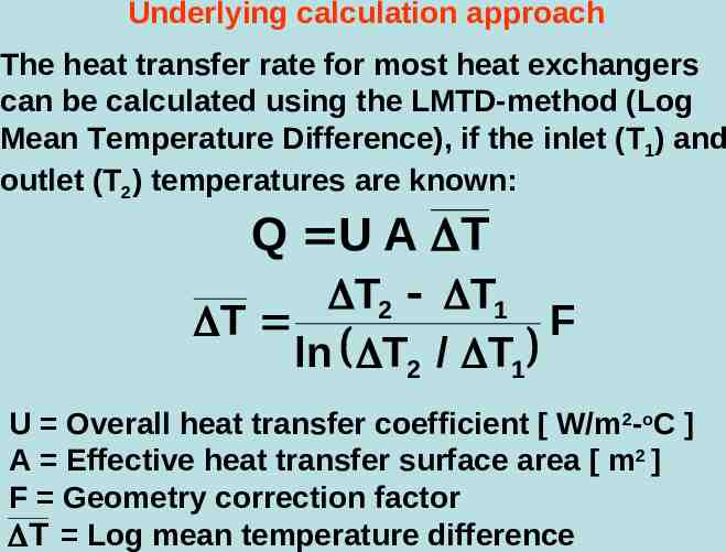
Underlying calculation approach The heat transfer rate for most heat exchangers can be calculated using the LMTD-method (Log Mean Temperature Difference), if the inlet (T1) and outlet (T2) temperatures are known: Q U A T T2 T1 T F ln T2 / T1 U Overall heat transfer coefficient [ W/m2-oC ] A Effective heat transfer surface area [ m2 ] F Geometry correction factor T Log mean temperature difference
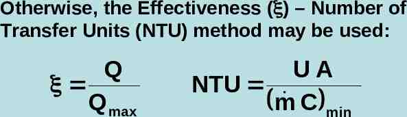
Otherwise, the Effectiveness ( ) – Number of Transfer Units (NTU) method may be used: Q Q max UA NTU m C min
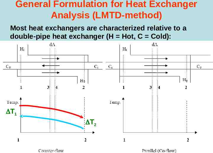
General Formulation for Heat Exchanger Analysis (LMTD-method) Most heat exchangers are characterized relative to a double-pipe heat exchanger (H Hot, C Cold): T1 T2
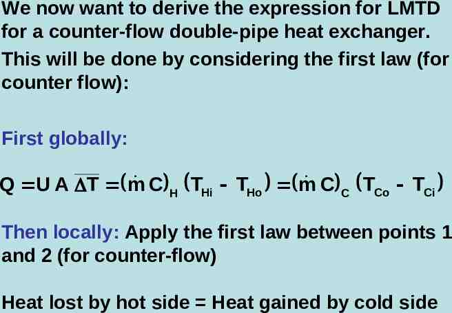
We now want to derive the expression for LMTD for a counter-flow double-pipe heat exchanger. This will be done by considering the first law (for counter flow): First globally: C H THi THo m C C TCo TCi Q U A T m Then locally: Apply the first law between points 1 and 2 (for counter-flow) Heat lost by hot side Heat gained by cold side
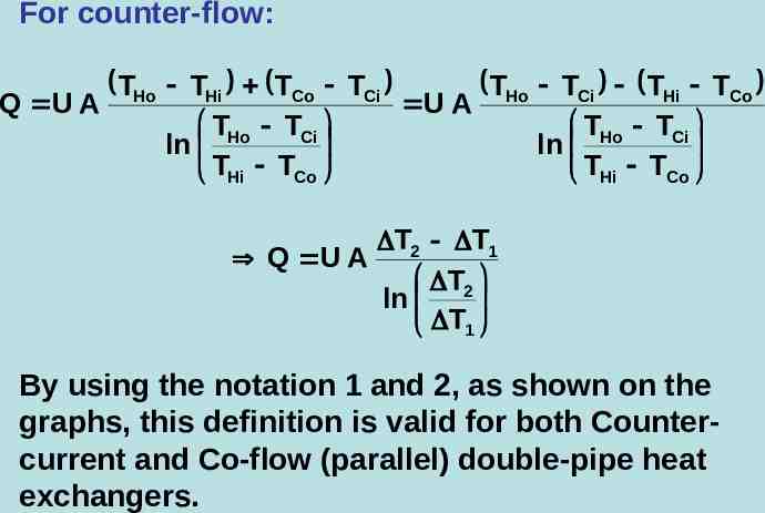
For counter-flow: Q U A THo THo TCi THi TCo THi TCo TCi U A THo TCi THo TCi ln ln THi TCo THi TCo T2 T1 Q U A T2 ln T1 By using the notation 1 and 2, as shown on the graphs, this definition is valid for both Countercurrent and Co-flow (parallel) double-pipe heat exchangers.
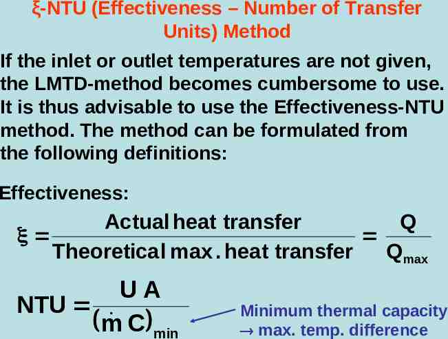
ξ-NTU (Effectiveness – Number of Transfer Units) Method If the inlet or outlet temperatures are not given, the LMTD-method becomes cumbersome to use. It is thus advisable to use the Effectiveness-NTU method. The method can be formulated from the following definitions: Effectiveness: Actual heat transfer Q Theoretica l max . heat transfer Q max UA NTU m C min Minimum thermal capacity max. temp. difference
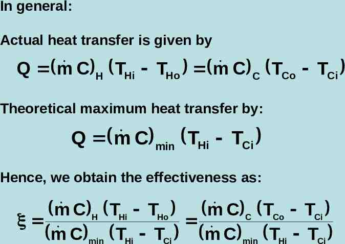
In general: Actual heat transfer is given by C H THi THo m C C TCo TCi Q m Theoretical maximum heat transfer by: C min THi TCi Q m Hence, we obtain the effectiveness as: C H THi THo C C TCo TCi m m C min THi TCi m C min THi TCi m
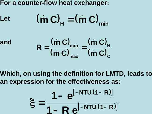
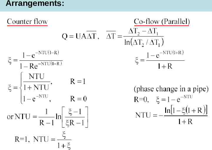
For a counter-flow heat exchanger: Let m C H m C min and m C min m C H R C max m C C m Which, on using the definition for LMTD, leads to an expression for the effectiveness as: NTU 1 R 1 e NTU 1 R 1 R e
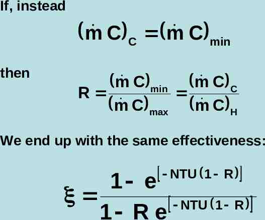
If, instead m C C m C min then C C m C min m R C max m C H m We end up with the same effectiveness: NTU 1 R 1 e NTU 1 R 1 R e
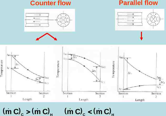
Counter flow C C m C H m C C m C H m Parallel flow
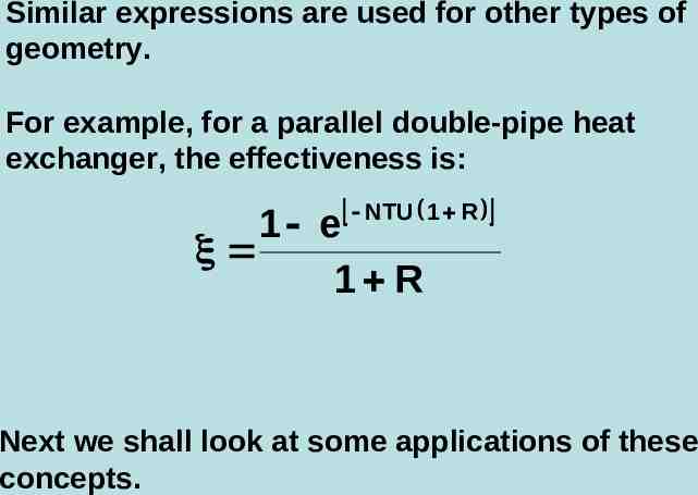
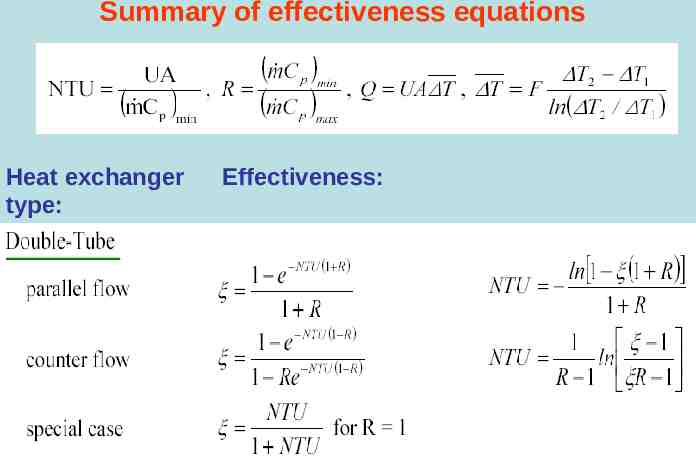
Similar expressions are used for other types of geometry. For example, for a parallel double-pipe heat exchanger, the effectiveness is: NTU 1 R 1 e 1 R Next we shall look at some applications of these concepts.
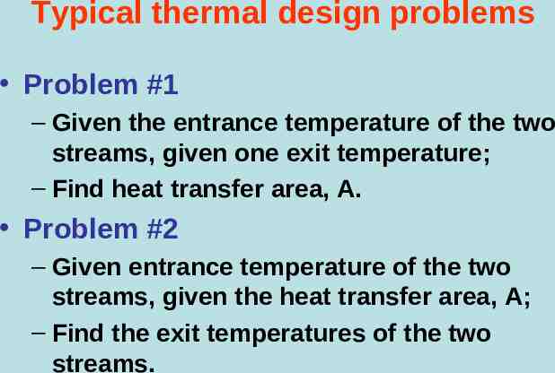
Typical thermal design problems Problem #1 – Given the entrance temperature of the two streams, given one exit temperature; – Find heat transfer area, A. Problem #2 – Given entrance temperature of the two streams, given the heat transfer area, A; – Find the exit temperatures of the two streams.
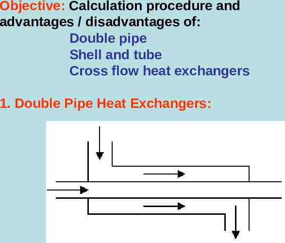
Objective: Calculation procedure and advantages / disadvantages of: Double pipe Shell and tube Cross flow heat exchangers 1. Double Pipe Heat Exchangers:
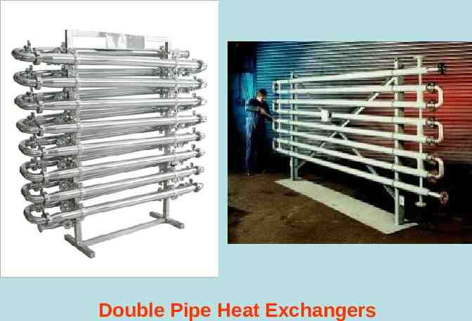
Double Pipe Heat Exchangers
Arrangements:
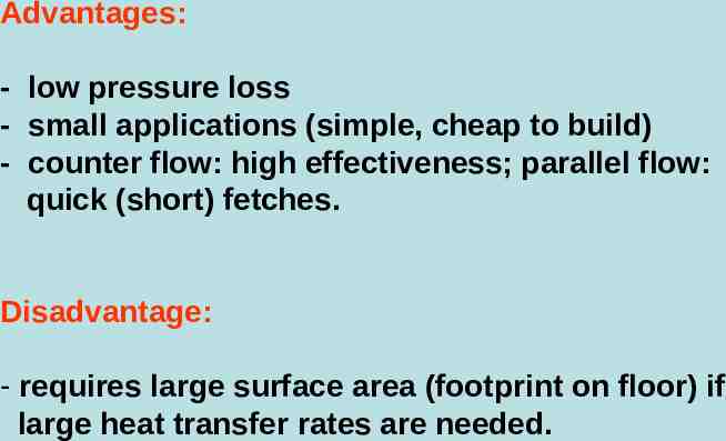
Advantages: - low pressure loss - small applications (simple, cheap to build) - counter flow: high effectiveness; parallel flow: quick (short) fetches. Disadvantage: - requires large surface area (footprint on floor) if large heat transfer rates are needed.
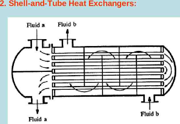
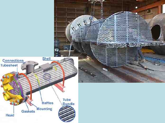
2. Shell-and-Tube Heat Exchangers:
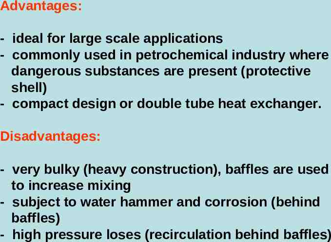
Advantages: - ideal for large scale applications - commonly used in petrochemical industry where dangerous substances are present (protective shell) - compact design or double tube heat exchanger. Disadvantages: - very bulky (heavy construction), baffles are used to increase mixing - subject to water hammer and corrosion (behind baffles) - high pressure loses (recirculation behind baffles)
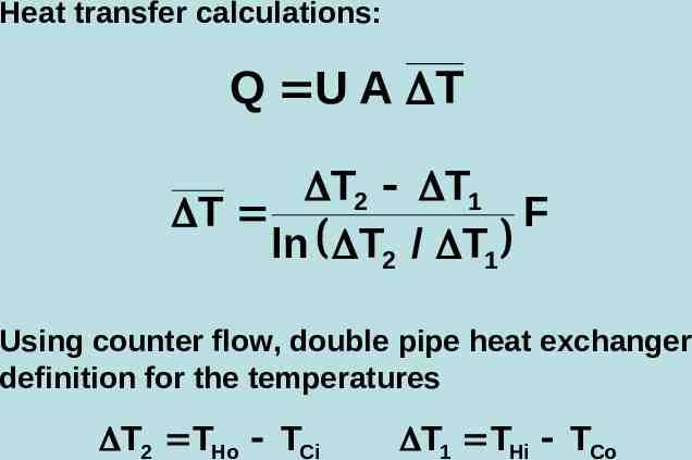
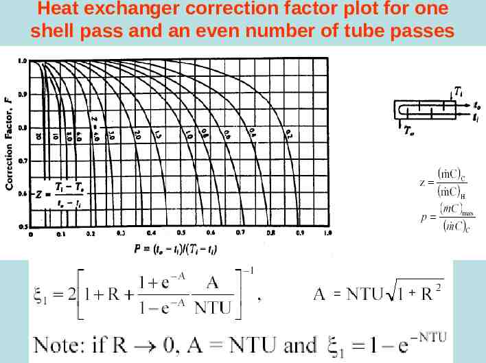
Heat transfer calculations: Q U A T T2 T1 T F ln T2 / T1 Using counter flow, double pipe heat exchanger definition for the temperatures T2 THo TCi T1 THi TCo
Heat exchanger correction factor plot for one shell pass and an even number of tube passes
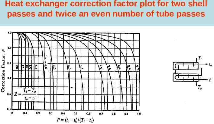
Heat exchanger correction factor plot for two shell passes and twice an even number of tube passes
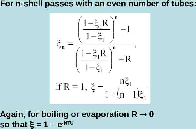
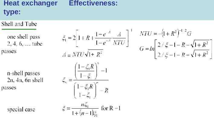
For n-shell passes with an even number of tubes: Again, for boiling or evaporation R 0 so that 1 – e-NTU
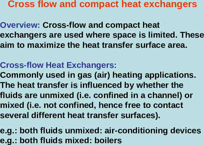
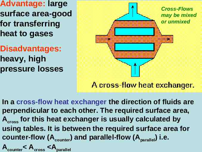
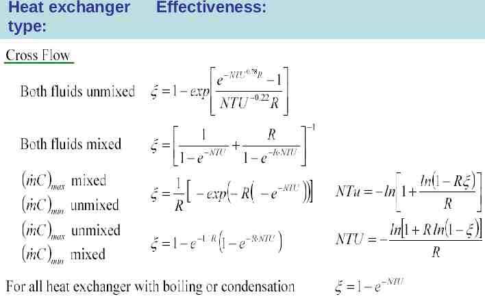
Cross flow and compact heat exchangers Overview: Cross-flow and compact heat exchangers are used where space is limited. These aim to maximize the heat transfer surface area. Cross-flow Heat Exchangers: Commonly used in gas (air) heating applications. The heat transfer is influenced by whether the fluids are unmixed (i.e. confined in a channel) or mixed (i.e. not confined, hence free to contact several different heat transfer surfaces). e.g.: both fluids unmixed: air-conditioning devices e.g.: both fluids mixed: boilers
Advantage: large surface area-good for transferring heat to gases Cross-Flows may be mixed or unmixed Disadvantages: heavy, high pressure losses In a cross-flow heat exchanger the direction of fluids are perpendicular to each other. The required surface area, Across for this heat exchanger is usually calculated by using tables. It is between the required surface area for counter-flow (Acounter) and parallel-flow (Aparallel) i.e. Acounter Across Aparallel
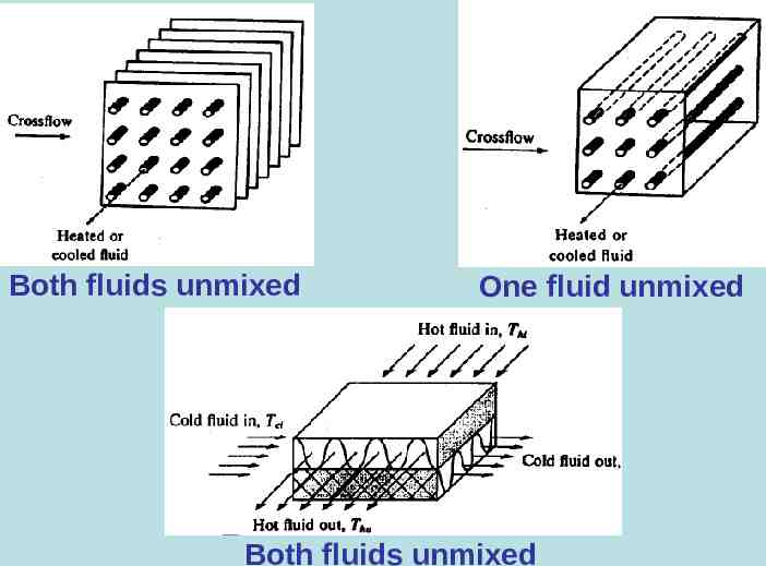
Both fluids unmixed One fluid unmixed Both fluids unmixed
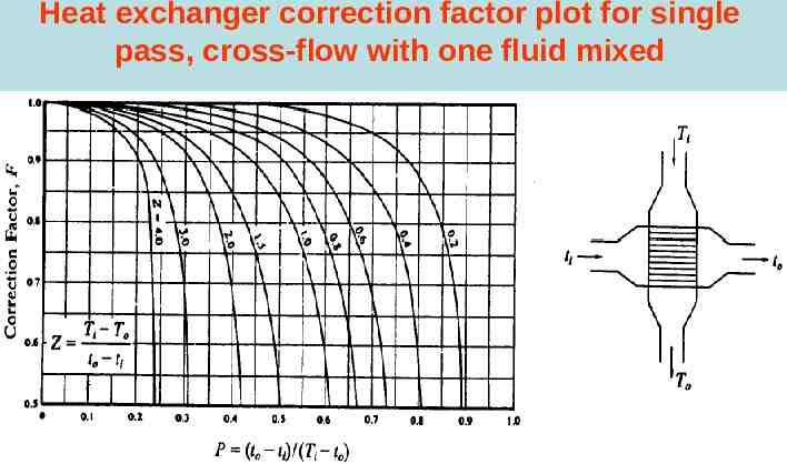
Cross-flow heat exchangers have the same analysis equations as before: Q U A T T2 T1 T F ln T2 / T1 with F as the correction factor (see graphs). The -NTU method may also be used
Heat exchanger correction factor plot for single pass, cross-flow with one fluid mixed
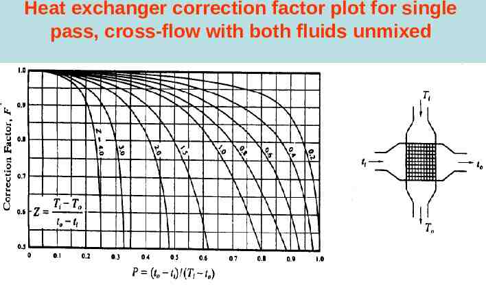
Heat exchanger correction factor plot for single pass, cross-flow with both fluids unmixed
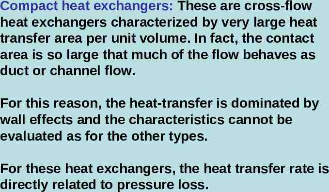
Compact heat exchangers: These are cross-flow heat exchangers characterized by very large heat transfer area per unit volume. In fact, the contact area is so large that much of the flow behaves as duct or channel flow. For this reason, the heat-transfer is dominated by wall effects and the characteristics cannot be evaluated as for the other types. For these heat exchangers, the heat transfer rate is directly related to pressure loss.
Advantages: - very small - ideal for transferring heat to / from fluids with very low conductivity or where the heat transfer must be done in very small spaces (e.g. electronic component cooling, cryogenic cooling, domestic furnaces). Disadvantages: - high manufacturing costs - very heavy - extremely high pressure losses.
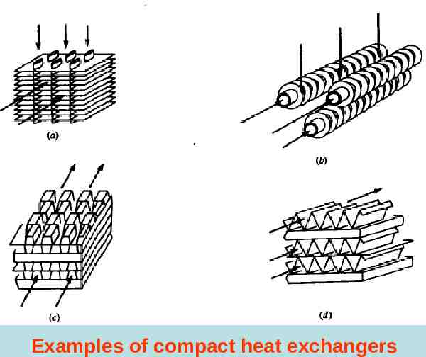
Examples of compact heat exchangers
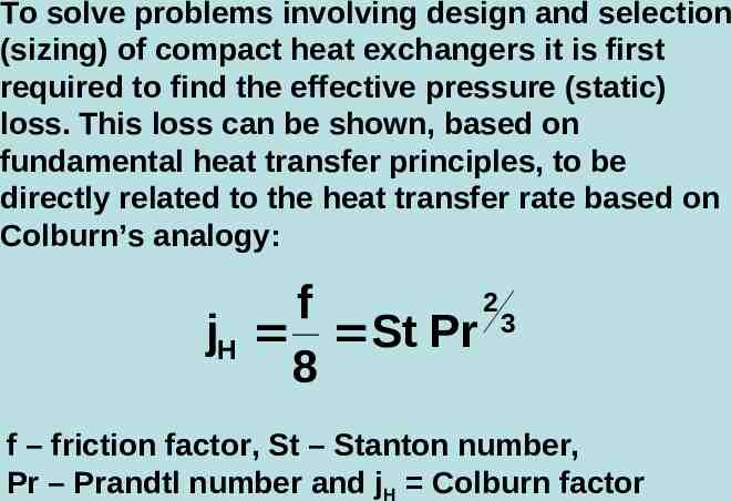
To solve problems involving design and selection (sizing) of compact heat exchangers it is first required to find the effective pressure (static) loss. This loss can be shown, based on fundamental heat transfer principles, to be directly related to the heat transfer rate based on Colburn’s analogy: 2 f jH St Pr 3 8 f – friction factor, St – Stanton number, Pr – Prandtl number and jH Colburn factor
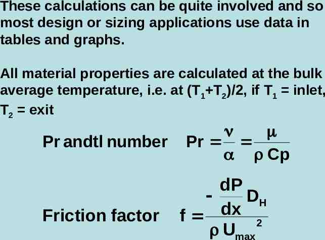
These calculations can be quite involved and so most design or sizing applications use data in tables and graphs. All material properties are calculated at the bulk average temperature, i.e. at (T1 T2)/2, if T1 inlet, T2 exit Pr andtl number Friction factor Pr Cp dP DH dx f 2 Umax
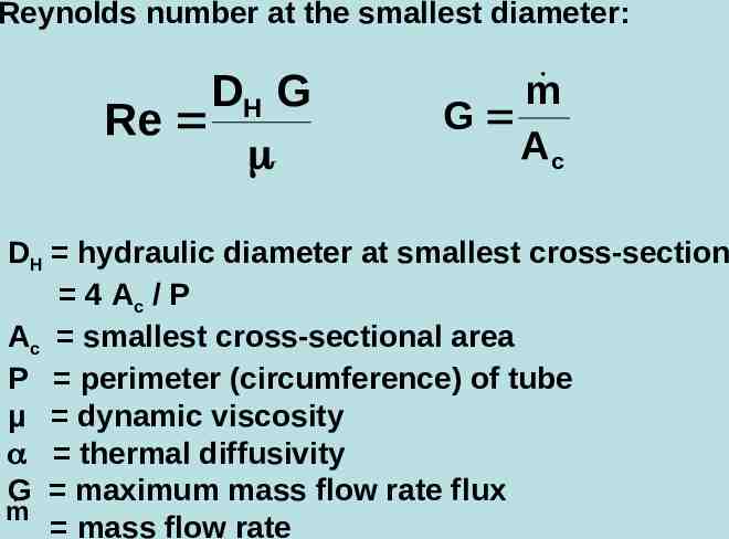
Reynolds number at the smallest diameter: DH G Re m G Ac DH hydraulic diameter at smallest cross-section 4 Ac / P Ac smallest cross-sectional area P perimeter (circumference) of tube µ dynamic viscosity thermal diffusivity G maximum mass flow rate flux m mass flow rate
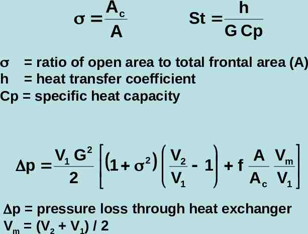
Ac A h St G Cp ratio of open area to total frontal area (A) h heat transfer coefficient Cp specific heat capacity V1 G2 A Vm 2 V2 1 1 f p 2 A c V1 V1 p pressure loss through heat exchanger Vm (V2 V1) / 2
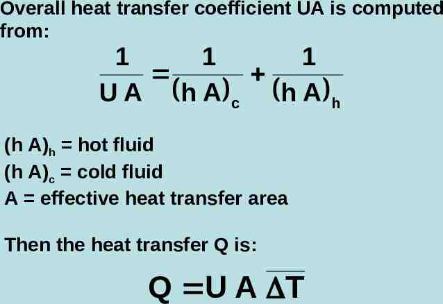
Overall heat transfer coefficient UA is computed from: 1 1 1 U A h A c h A h (h A)h hot fluid (h A)c cold fluid A effective heat transfer area Then the heat transfer Q is: Q U A T
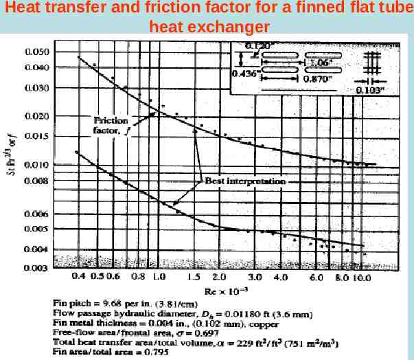
Heat transfer and friction factor for a finned flat tube heat exchanger
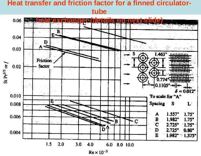
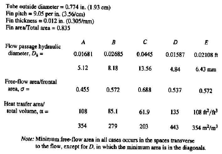
Heat transfer and friction factor for a finned circulatortube heat exchanger (details on next slide)
Summary
Summary of effectiveness equations Heat exchanger type: Effectiveness:
Heat exchanger type: Effectiveness:
Heat exchanger type: Effectiveness:
Example questions
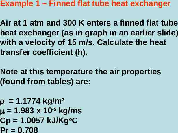
Example 1 – Finned flat tube heat exchanger Air at 1 atm and 300 K enters a finned flat tube heat exchanger (as in graph in an earlier slide) with a velocity of 15 m/s. Calculate the heat transfer coefficient (h). Note at this temperature the air properties (found from tables) are: 1.1774 kg/m3 1.983 x 10⁻⁵ kg/ms Cp 1.0057 kJ/KgoC Pr 0.708
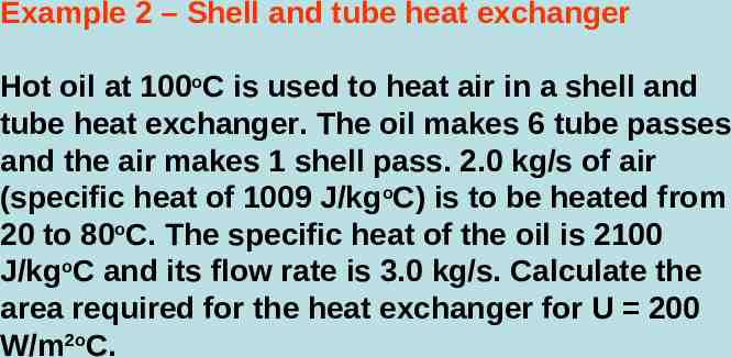
Example 2 – Shell and tube heat exchanger Hot oil at 100oC is used to heat air in a shell and tube heat exchanger. The oil makes 6 tube passes and the air makes 1 shell pass. 2.0 kg/s of air (specific heat of 1009 J/kgoC) is to be heated from 20 to 80oC. The specific heat of the oil is 2100 J/kgoC and its flow rate is 3.0 kg/s. Calculate the area required for the heat exchanger for U 200 W/m2oC.
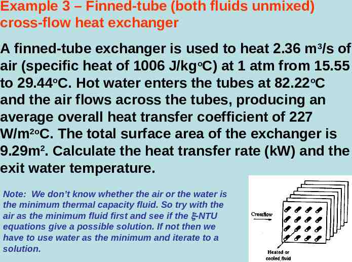
Example 3 – Finned-tube (both fluids unmixed) cross-flow heat exchanger A finned-tube exchanger is used to heat 2.36 m3/s of air (specific heat of 1006 J/kgoC) at 1 atm from 15.55 to 29.44oC. Hot water enters the tubes at 82.22oC and the air flows across the tubes, producing an average overall heat transfer coefficient of 227 W/m2oC. The total surface area of the exchanger is 9.29m2. Calculate the heat transfer rate (kW) and the exit water temperature. Note: We don’t know whether the air or the water is the minimum thermal capacity fluid. So try with the air as the minimum fluid first and see if the -NTU equations give a possible solution. If not then we have to use water as the minimum and iterate to a solution.