ECE 476 POWER SYSTEM ANALYSIS Lecture 14 Power Flow Professor


46 Slides2.01 MB
ECE 476 POWER SYSTEM ANALYSIS Lecture 14 Power Flow Professor Tom Overbye Department of Electrical and Computer Engineering
Announcements Be reading Chapter 6, also Chapter 2.4 (Network Equations). HW 5 is 2.38, 6.9, 6.18, 6.30, 6.34, 6.38; do by October 6 but does not need to be turned in. First exam is October 11 during class. Closed book, closed notes, one note sheet and calculators allowed. Exam covers thru the end of lecture 13 (today) An example previous exam (2008) is posted. Note this is exam was given earlier in the semester in 2008 so it did not include power flow, but the 2011 exam will (at least partially) 2
Modeling Voltage Dependent Load So far we've assumed that the load is independent of the bus voltage (i.e., constant power). However, the power flow can be easily extended to include voltage depedence with both the real and reactive load. This is done by making PDi and Q Di a function of Vi : n Vi Vk (Gik cos ik Bik sin ik ) PGi PDi ( Vi ) 0 Vi Vk (Gik sin ik Bik cos ik ) QGi QDi ( Vi ) 0 k 1 n k 1 3
Voltage Dependent Load Example In previous two bus example now assume the load is constant impedance, so P2 (x) V2 (10sin 2 ) 2.0 V2 2 0 2 2 Q2 (x) V2 ( 10 cos 2 ) V2 (10) 1.0 V2 0 Now calculate the power flow Jacobian 10 V2 cos 2 J ( x) 10 V2 sin 2 10sin 2 4.0 V2 10 cos 2 20 V2 2.0 V2 4
Voltage Dependent Load, cont'd Again set v 0, guess x (0) 0 1 Calculate 2 V (10sin ) 2.0 V 2.0 2 2 2 (0) f(x ) 2 2 1.0 V2 ( 10cos 2 ) V2 (10) 1.0 V2 10 4 (0) J (x ) 0 12 Solve x (1) 0 10 4 1 0 12 1 2.0 1.0 0.1667 0.9167 5
Voltage Dependent Load, cont'd With constant impedance load the MW/Mvar load at bus 2 varies with the square of the bus 2 voltage magnitude. This if the voltage level is less than 1.0, the load is lower than 200/100 MW/Mvar 160.0 MW 120.0 MVR One -160.0 MW -80.0 MVR Line Z 0.1j 1.000 pu 160.0 MW 120.0 MVR Two 0.894 pu -10.304 Deg 160 MW 80 MVR 6
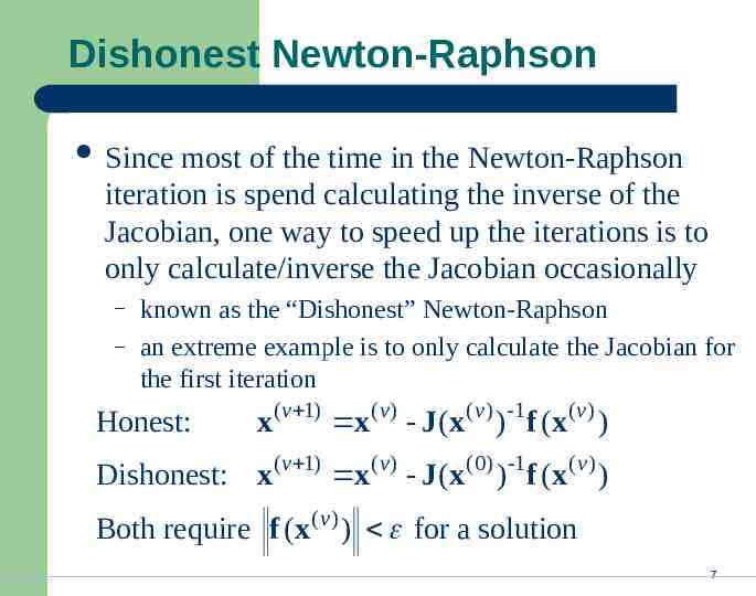
Dishonest Newton-Raphson Since most of the time in the Newton-Raphson iteration is spend calculating the inverse of the Jacobian, one way to speed up the iterations is to only calculate/inverse the Jacobian occasionally – – known as the “Dishonest” Newton-Raphson an extreme example is to only calculate the Jacobian for the first iteration Honest: x(v 1) x( v ) - J (x( v ) )-1f ( x( v ) ) Dishonest: x(v 1) x( v ) - J ( x(0) )-1 f ( x( v ) ) (v ) Both require f (x ) for a solution 7
Dishonest Newton-Raphson Example Use the Dishonest Newton-Raphson to solve f ( x) x 2 - 2 0 x (v) x ( v ) x ( v 1) (0) 1 df ( x ) (v) f ( x ) dx 1 (v) 2 (0) (( x ) - 2) 2x (v) 1 x (0) (( x ( v ) ) 2 - 2) 2x 8
Dishonest N-R Example, cont’d x ( v 1) x (v) 1 (v) 2 (0) (( x ) - 2) 2x Guess x (0) 1. Iteratively solving we get v 0 x ( v ) (honest) 1 1 2 3 1.5 1.41667 1.41422 4 1.41422 x ( v ) (dishonest) 1 We pay a price in increased 1.5 iterations, but 1.375 with decreased 1.429 computation 1.408 per iteration 9
Two Bus Dishonest ROC Slide shows the region of convergence for different initial guesses for the 2 bus case using the Dishonest N-R Red region converges to the high voltage solution, while the yellow region converges to the low voltage solution 10
Honest N-R Region of Convergence Maximum of 15 iterations 11
Decoupled Power Flow The completely Dishonest Newton-Raphson is not used for power flow analysis. However several approximations of the Jacobian matrix are used. One common method is the decoupled power flow. In this approach approximations are used to decouple the real and reactive power equations. 12
Decoupled Power Flow Formulation General form of the power flow problem P (v ) θ Q ( v ) θ P V (v ) (v) (v ) θ P ( x ) (v ) f ( x ) ( v ) Q (v ) V Q(x ( v ) ) V where P2 (x(v ) ) PD 2 PG 2 (v) P (x ) P ( x( v ) ) P P n Dn Gn 13
Decoupling Approximation P ( v ) Q ( v ) Usually the off-diagonal matrices, and V θ are small. Therefore we approximate them as zero: P ( v ) 0 (v) (v ) θ P ( x ) θ (v ) f ( x ) (v) ( v ) (v) Q V Q ( x ) 0 V Then the problem can be decoupled θ (v) P θ (v) 1 P (x (v) ) V (v) Q V (v ) 1 Q (x ( v ) ) 14
Off-diagonal Jacobian Terms Justification for Jacobian approximations: 1. Usually r x, therefore Gij Bij 2. Usually ij is small so sin ij 0 Therefore Pi Vi Gij cos ij Bij sin ij Vj Qi θ j 0 Vi V j Gij cos ij Bij sin ij 0 15
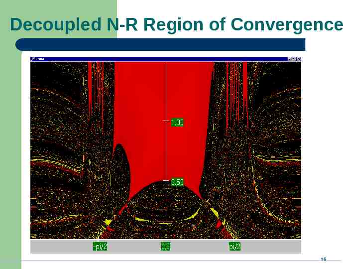
Decoupled N-R Region of Convergence 16
Fast Decoupled Power Flow By continuing with our Jacobian approximations we can actually obtain a reasonable approximation that is independent of the voltage magnitudes/angles. This means the Jacobian need only be built/inverted once. This approach is known as the fast decoupled power flow (FDPF) FDPF uses the same mismatch equations as standard power flow so it should have same solution The FDPF is widely used, particularly when we only need an approximate solution 17
FDPF Approximations The FDPF makes the following approximations: 1. G ij 0 2. Vi 3. sin ij 0 1 cos ij 1 Then (v ) (v) P ( x ) Q ( x ) (v ) (v) 1 1 θ B V B (v ) (v ) V V Where B is just the imaginary part of the Ybus G jB, except the slack bus row/column are omitted 18
FDPF Three Bus Example Use the FDPF to solve the following three bus system Line Z j0.07 One Two Line Z j0.05 Three Line Z j0.1 200 MW 100 MVR 1.000 pu 200 MW 100 MVR Ybus 20 34.3 14.3 j 14.3 24.3 10 10 30 20 19
FDPF Three Bus Example, cont’d Ybus B 1 20 34.3 14.3 24.3 10 j 14.3 24.3 10 B 30 10 10 30 20 0.0477 0.0159 0.0159 0.0389 Iteratively solve, starting with an initial voltage guess 2 3 2 3 (0) (0) 0 0 (1) 0 0.0477 0.0159 2 0.1272 0 0.0159 0.0389 2 0.1091 V 2 V 3 1 1 20
FDPF Three Bus Example, cont’d V 2 V 3 (1) 1 0.0477 0.0159 1 0.9364 1 0.0159 0.0389 1 0.9455 Pi (x ) n PDi PGi Vk (Gik cos ik Bik sin ik ) Vi Vi k 1 2 3 (2) V 2 V 3 0.1272 0.0477 0.0159 0.151 0.1361 0.1091 0.0159 0.0389 0.107 0.1156 (2) 0.924 0.936 0.1384 Actual solution: θ 0.1171 0.9224 V 0.9338 21
FDPF Region of Convergence 22
“DC” Power Flow The “DC” power flow makes the most severe approximations: – completely ignore reactive power, assume all the voltages are always 1.0 per unit, ignore line conductance This makes the power flow a linear set of equations, which can be solved directly θ B 1 P 23
Power System Control A major problem with power system operation is the limited capacity of the transmission system – – – lines/transformers have limits (usually thermal) no direct way of controlling flow down a transmission line (e.g., there are no valves to close to limit flow) open transmission system access associated with industry restructuring is stressing the system in new ways We need to indirectly control transmission line flow by changing the generator outputs 24
DC Power Flow Example 25
DC Power Flow Example 26
DC Power Flow 5 Bus Example One 360 MW 0 Mvar A Five Four MVA A Three MVA 520 MW A MVA 0 Mvar slack 1.000 pu 0.000 Deg 1.000 pu -4.125 Deg A A MVA MVA 1.000 pu -18.695 Deg 1.000 pu -1.997 Deg 80 MW 0 Mvar 1.000 pu 0.524 Deg Two 800 MW 0 Mvar Notice with the dc power flow all of the voltage magnitudes are 1 per unit. 27
Indirect Transmission Line Control What we would like to determine is how a change in generation at bus k affects the power flow on a line from bus i to bus j. The assumption is that the change in generation is absorbed by the slack bus 28
Power Flow Simulation - Before One way to determine the impact of a generator change is to compare a before/after power flow. For example below is a three bus case with an overload 131.9 MW 124% One 200.0 MW 71.0 MVR Two 68.1 MW 68.1 MW 200 MW 100 MVR Z for all lines j0.1 Three 1.000 pu 0 MW 64 MVR 29
Power Flow Simulation - After Increasing the generation at bus 3 by 95 MW (and hence decreasing it at bus 1 by a corresponding amount), results in a 31.3 drop in the MW flow on the line from bus 1 to 2. 101.6 MW 100% One 105.0 MW 64.3 MVR Two 3.4 MW Z for all lines j0.1 Limit for all lines 150 MVA Three 98.4 MW 200 MW 100 MVR 92% 1.000 pu 95 MW 64 MVR 30
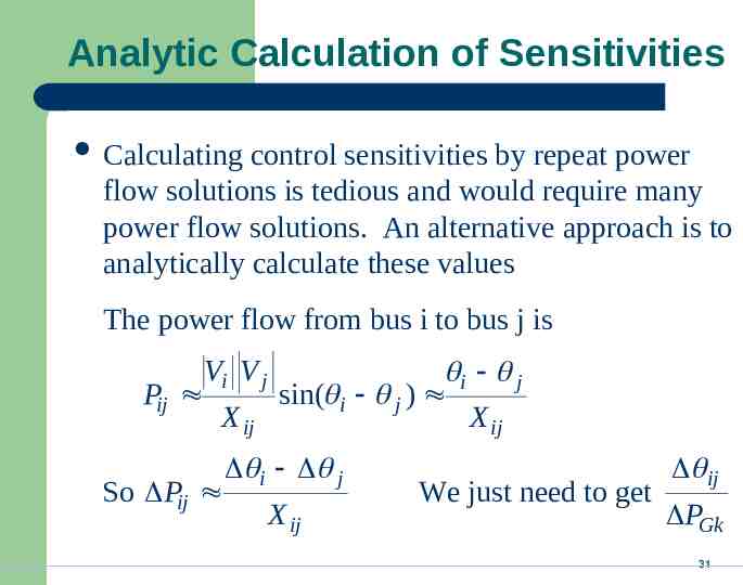
Analytic Calculation of Sensitivities Calculating control sensitivities by repeat power flow solutions is tedious and would require many power flow solutions. An alternative approach is to analytically calculate these values The power flow from bus i to bus j is Pij Vi V j X ij So Pij i j sin( i j ) X ij i j X ij We just need to get ij PGk 31
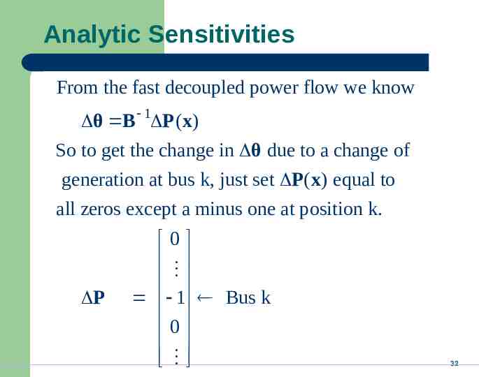
Analytic Sensitivities From the fast decoupled power flow we know θ B 1 P (x) So to get the change in θ due to a change of generation at bus k, just set P( x) equal to all zeros except a minus one at position k. P 0 1 Bus k 0 32
Three Bus Sensitivity Example For the previous three bus case with Zline j 0.1 20 10 10 20 10 Ybus j 10 20 10 B 10 20 10 10 20 Hence for a change of generation at bus 3 1 20 10 0 0.0333 10 20 1 0.0667 0.0667 0 Then P3 to 1 0.667 pu 0.1 P3 to 2 0.333 pu P 2 to 1 0.333 pu 2 3 33
Balancing Authority Areas An balancing authority area (use to be called operating areas) has traditionally represented the portion of the interconnected electric grid operated by a single utility Transmission lines that join two areas are known as tie-lines. The net power out of an area is the sum of the flow on its tielines. The flow out of an area is equal to total gen - total load - total losses tie-flow 34
Area Control Error (ACE) The area control error (ace) is the difference between the actual flow out of an area and the scheduled flow, plus a frequency component Ideally the ACE Pint should Psched always 10 be f zero. Because the load is constantly changing, each utility must constantly change its generation to “chase” the ACE. ace 35
Automatic Generation Control Most utilities use automatic generation control (AGC) to automatically change their generation to keep their ACE close to zero. Usually the utility control center calculates ACE based upon tie-line flows; then the AGC module sends control signals out to the generators every couple seconds. 36
Power Transactions Power transactions are contracts between generators and loads to do power transactions. Contracts can be for any amount of time at any price for any amount of power. Scheduled power transactions are implemented by modifying the value of Psched used in the ACE calculation 37
PTDFs Power transfer distribution factors (PTDFs) show the linear impact of a transfer of power. PTDFs calculated using the fast decoupled power flow B matrix θ B 1 P (x) Once we know θ we can derive the change in the transmission line flows Except now we modify several elements in P (x), in portion to how the specified generators would participate in the power transfer 38
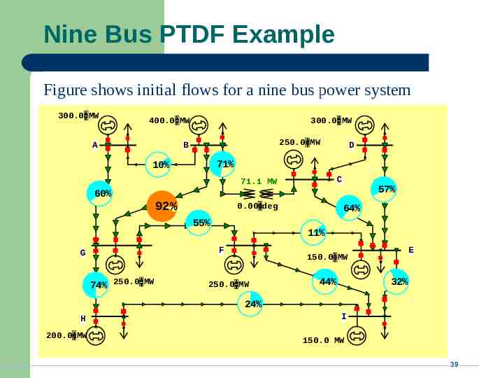
Nine Bus PTDF Example Figure shows initial flows for a nine bus power system 300.0 MW 400.0 MW A 300.0 MW 250.0 MW B 71% 10% C 71.1 MW 60% 92% 0.00 deg 55% 74% 250.0 MW 57% 64% 11% F G D E 150.0 MW 250.0 MW 44% 32% 24% H 200.0 MW I 150.0 MW 39
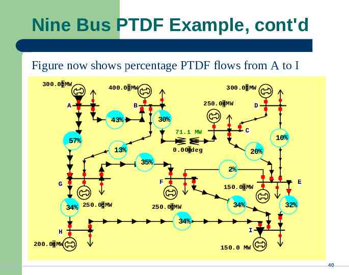
Nine Bus PTDF Example, cont'd Figure now shows percentage PTDF flows from A to I 300.0 MW 400.0 MW A 300.0 MW 250.0 MW B D 30% 43% C 71.1 MW 10% 57% 13% 0.00 deg 35% 2% F G 34% 250.0 MW 20% E 150.0 MW 250.0 MW 34% 32% 34% H 200.0 MW I 150.0 MW 40
Nine Bus PTDF Example, cont'd Figure now shows percentage PTDF flows from G to F 300.0 MW 400.0 MW A 300.0 MW 250.0 MW B D 18% 6% C 71.1 MW 6% 6% 12% 0.00 deg 61% 19% F G 21% 250.0 MW 12% 150.0 MW 250.0 MW E 20% 21% H 200.0 MW I 150.0 MW 41
WE to TVA PTDFs 42
Line Outage Distribution Factors (LODFS) LODFs are used to approximate the change in the flow on one line caused by the outage of a second line – – – typically they are only used to determine the change in the MW flow LODFs are used extensively in real-time operations LODFs are state-independent but do dependent on the assumed network topology Pl LODFl ,k Pk 43
Flowgates The real-time loading of the power grid is accessed via “flowgates” A flowgate “flow” is the real power flow on one or more transmission element for either base case conditions or a single contingency – contingent flows are determined using LODFs Flowgates are used as proxies for other types of limits, such as voltage or stability limits Flowgates are calculated using a spreadsheet 44
NERC Regional Reliability Councils NERC is the North American Electric Reliability Council 45
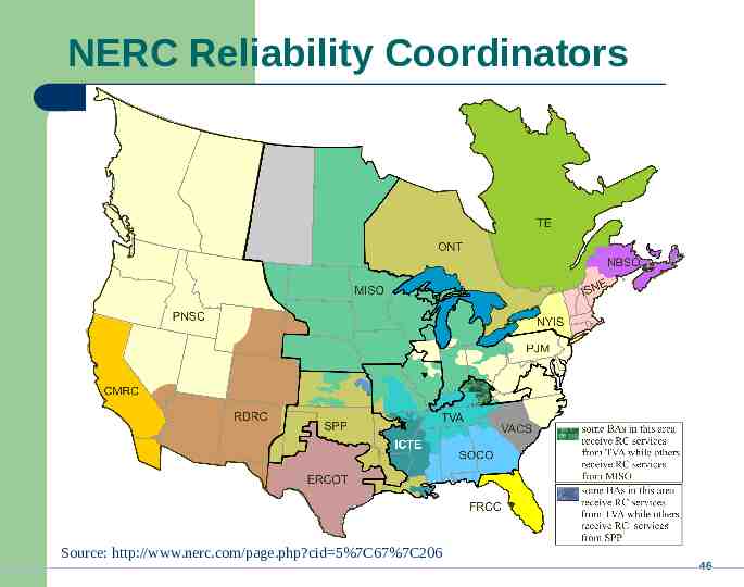
NERC Reliability Coordinators Source: http://www.nerc.com/page.php?cid 5%7C67%7C206 46