Chapter 5 Link Layer and LANs Computer Networking: A Top Down

91 Slides2.96 MB
Chapter 5 Link Layer and LANs Computer Networking: A Top Down Approach 4th edition. Jim Kurose, Keith Ross Addison-Wesley, July 2007. 5: DataLink Layer 5-1
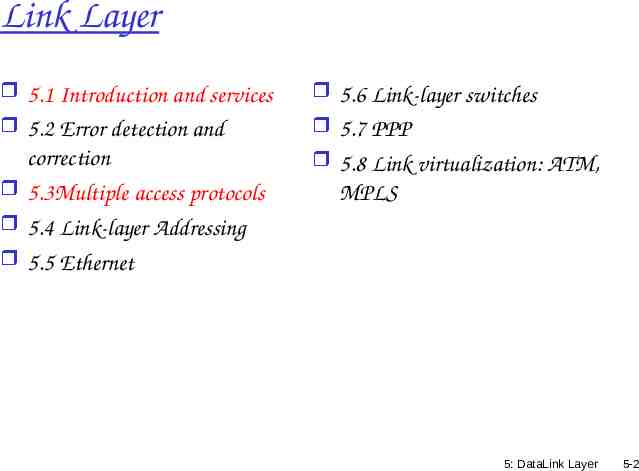
Link Layer 5.1 Introduction and services 5.2 Error detection and 5.6 Link-layer switches 5.7 PPP correction 5.3Multiple access protocols 5.4 Link-layer Addressing 5.5 Ethernet 5.8 Link virtualization: ATM, MPLS 5: DataLink Layer 5-2
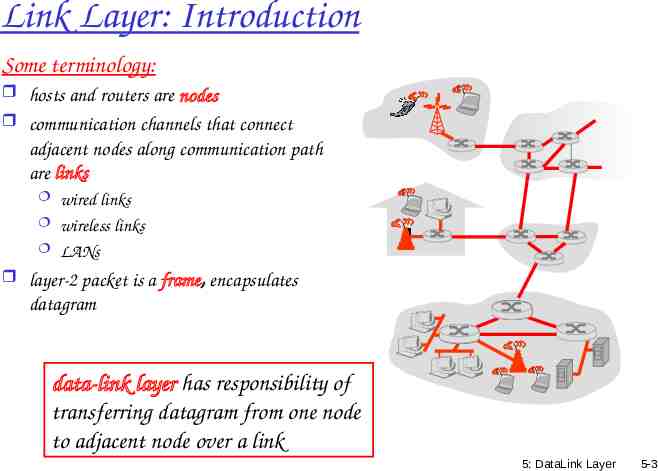
Link Layer: Introduction Some terminology: hosts and routers are nodes communication channels that connect adjacent nodes along communication path are links wired links wireless links LANs layer-2 packet is a frame, encapsulates datagram data-link layer has responsibility of transferring datagram from one node to adjacent node over a link 5: DataLink Layer 5-3
Link Layer Services framing, link access: encapsulate datagram into frame, adding header, trailer channel access if shared medium “MAC” addresses used in frame headers to identify source, dest different from IP address! reliable delivery between adjacent nodes we learned how to do this already (chapter 3)! seldom used on low bit-error link (fiber, some twisted pair) wireless links: high error rates Q: why both link-level and end-end reliability? 5: DataLink Layer 5-4
Link Layer Services (more) flow control: pacing between adjacent sending and receiving nodes error detection: errors caused by signal attenuation, noise. receiver detects presence of errors: signals sender for retransmission or drops frame error correction: receiver identifies and corrects bit error(s) without resorting to retransmission half-duplex and full-duplex with half duplex, nodes at both ends of link can transmit, but not at same time 5: DataLink Layer 5-5
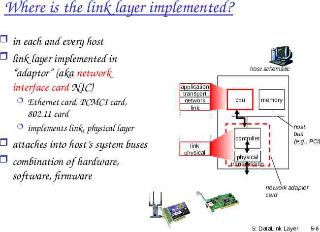
Where is the link layer implemented? in each and every host link layer implemented in “adaptor” (aka network interface card NIC) Ethernet card, PCMCI card, 802.11 card implements link, physical layer attaches into host’s system buses combination of hardware, host schematic application transport network link cpu memory controller link physical host bus (e.g., PCI) physical transmission software, firmware network adapter card 5: DataLink Layer 5-6
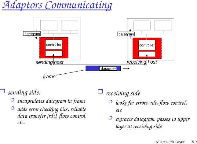
Adaptors Communicating datagram datagram controller controller receiving host sending host datagram frame sending side: encapsulates datagram in frame adds error checking bits, reliable data transfer (rdt), flow control, etc. receiving side looks for errors, rdt, flow control, etc extracts datagram, passes to upper layer at receiving side 5: DataLink Layer 5-7
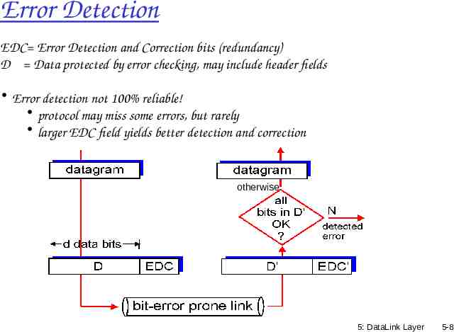
Error Detection EDC Error Detection and Correction bits (redundancy) D Data protected by error checking, may include header fields Error detection not 100% reliable! protocol may miss some errors, but rarely larger EDC field yields better detection and correction otherwise 5: DataLink Layer 5-8
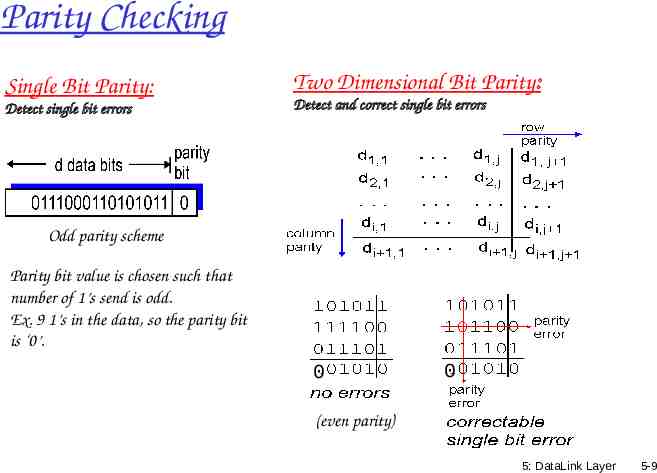
Parity Checking Single Bit Parity: Detect single bit errors Two Dimensional Bit Parity: Detect and correct single bit errors Odd parity scheme Parity bit value is chosen such that number of 1’s send is odd. Ex. 9 1’s in the data, so the parity bit is ‘0’. 0 0 (even parity) 5: DataLink Layer 5-9
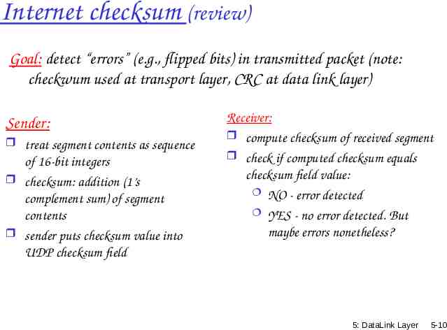
Internet checksum (review) Goal: detect “errors” (e.g., flipped bits) in transmitted packet (note: checkwum used at transport layer, CRC at data link layer) Sender: treat segment contents as sequence of 16-bit integers checksum: addition (1’s complement sum) of segment contents sender puts checksum value into UDP checksum field Receiver: compute checksum of received segment check if computed checksum equals checksum field value: NO - error detected YES - no error detected. But maybe errors nonetheless? 5: DataLink Layer 5-10
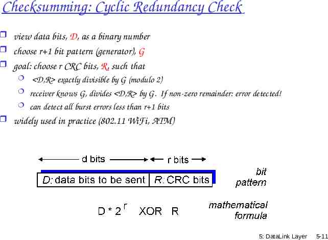
Checksumming: Cyclic Redundancy Check view data bits, D, as a binary number choose r 1 bit pattern (generator), G goal: choose r CRC bits, R, such that D,R exactly divisible by G (modulo 2) receiver knows G, divides D,R by G. If non-zero remainder: error detected! can detect all burst errors less than r 1 bits widely used in practice (802.11 WiFi, ATM) 5: DataLink Layer 5-11
Link Layer 5.1 Introduction and services 5.2 Error detection and 5.6 Link-layer switches 5.7 PPP correction 5.3Multiple access protocols 5.4 Link-layer Addressing 5.5 Ethernet 5.8 Link Virtualization: ATM, MPLS 5: DataLink Layer 5-12
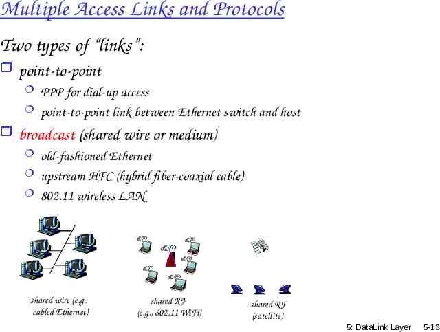
Multiple Access Links and Protocols Two types of “links”: point-to-point PPP for dial-up access point-to-point link between Ethernet switch and host broadcast (shared wire or medium) old-fashioned Ethernet upstream HFC (hybrid fiber-coaxial cable) 802.11 wireless LAN shared wire (e.g., cabled Ethernet) shared RF (e.g., 802.11 WiFi) shared RF (satellite) 5: DataLink Layer 5-13
Multiple Access protocols single shared broadcast channel two or more simultaneous transmissions by nodes: interference collision if node receives two or more signals at the same time multiple access protocol distributed algorithm that determines how nodes share channel, i.e., determine when node can transmit communication about channel sharing must use channel itself! no out-of-band channel for coordination 5: DataLink Layer 5-14
Ideal Multiple Access Protocol Broadcast channel of rate R bps 1. when one node wants to transmit, it can send at rate R. 2. when M nodes want to transmit, each can send at average rate R/M 3. fully decentralized: no special node to coordinate transmissions no synchronization of clocks, slots 4. simple 5: DataLink Layer 5-15
MAC Protocols: a taxonomy Three broad classes: Channel Partitioning divide channel into smaller “pieces” (time slots, frequency, code) allocate piece to node for exclusive use Random Access channel not divided, allow collisions “recover” from collisions “Taking turns” nodes take turns, but nodes with more to send can take longer turns 5: DataLink Layer 5-16
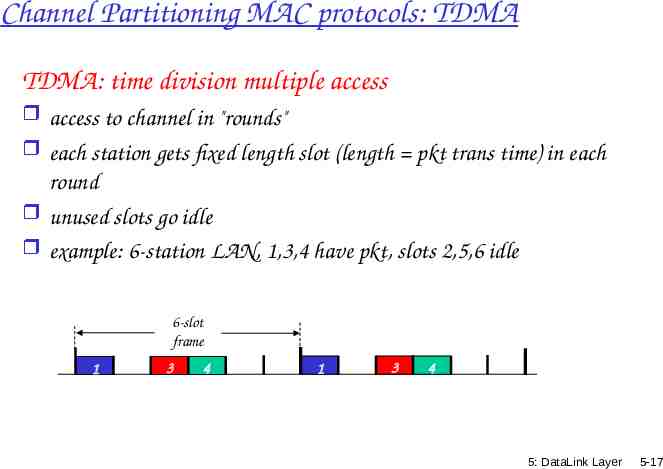
Channel Partitioning MAC protocols: TDMA TDMA: time division multiple access access to channel in "rounds" each station gets fixed length slot (length pkt trans time) in each round unused slots go idle example: 6-station LAN, 1,3,4 have pkt, slots 2,5,6 idle 6-slot frame 1 3 4 1 3 4 5: DataLink Layer 5-17
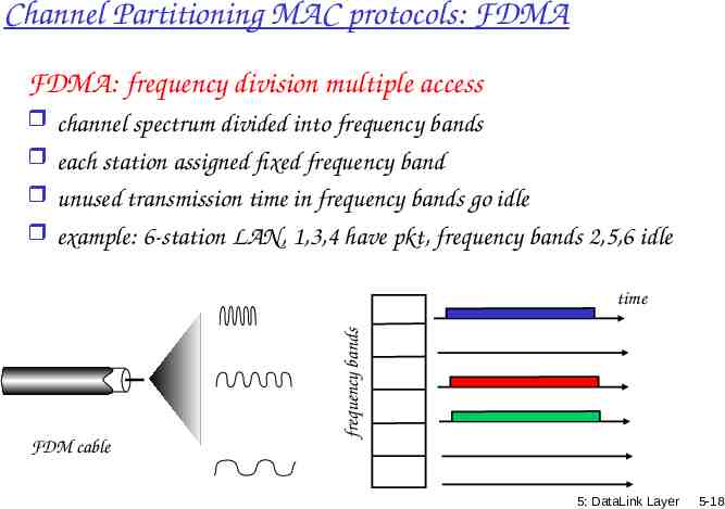
Channel Partitioning MAC protocols: FDMA FDMA: frequency division multiple access channel spectrum divided into frequency bands each station assigned fixed frequency band unused transmission time in frequency bands go idle example: 6-station LAN, 1,3,4 have pkt, frequency bands 2,5,6 idle frequency bands time FDM cable 5: DataLink Layer 5-18
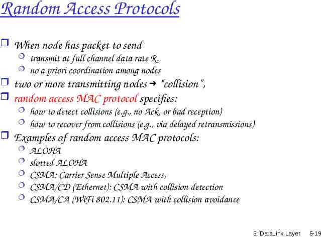
Random Access Protocols When node has packet to send transmit at full channel data rate R. no a priori coordination among nodes two or more transmitting nodes “collision”, random access MAC protocol specifies: how to detect collisions (e.g., no Ack, or bad reception) how to recover from collisions (e.g., via delayed retransmissions) Examples of random access MAC protocols: ALOHA slotted ALOHA CSMA: Carrier Sense Multiple Access, CSMA/CD (Ethernet): CSMA with collision detection CSMA/CA (WiFi 802.11): CSMA with collision avoidance 5: DataLink Layer 5-19
Random MAC (Medium Access Control) Techniques ALOHA (‘70) [packet radio network] A station sends whenever it has a packet/frame Listens for round-trip-time delay for Ack If no Ack then re-send packet/frame after random delay too short more collisions too long under utilization No carrier sense is used If two stations transmit about the same time frames collide Utilization of ALOHA is low 18% 5: DataLink Layer 5-20
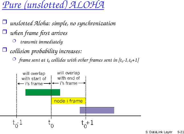
Pure (unslotted) ALOHA unslotted Aloha: simple, no synchronization when frame first arrives transmit immediately collision probability increases: frame sent at t0 collides with other frames sent in [t0-1,t0 1] 5: DataLink Layer 5-21
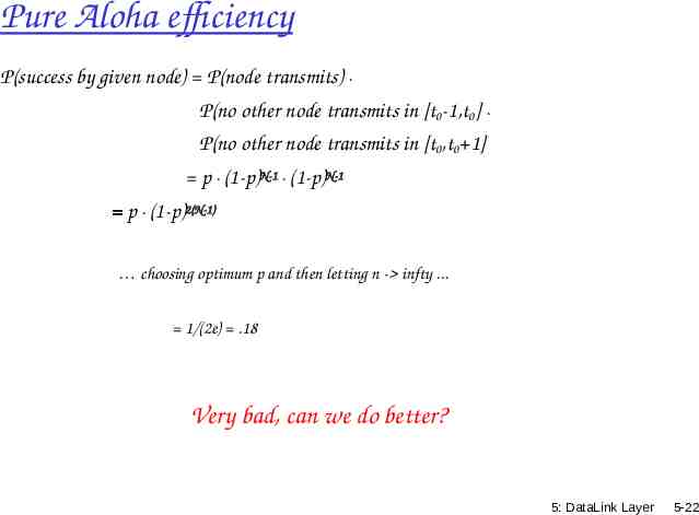
Pure Aloha efficiency P(success by given node) P(node transmits) . P(no other node transmits in [t0-1,t0] . P(no other node transmits in [t0,t0 1] p . (1-p)N-1 . (1-p)N-1 p . (1-p)2(N-1) choosing optimum p and then letting n - infty . 1/(2e) .18 Very bad, can we do better? 5: DataLink Layer 5-22
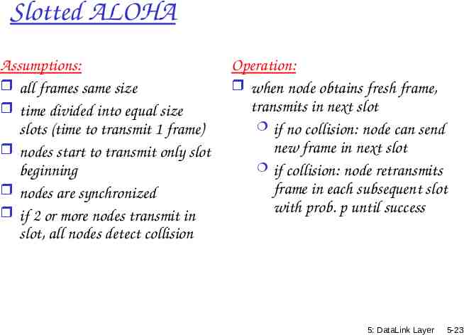
Slotted ALOHA Assumptions: all frames same size time divided into equal size slots (time to transmit 1 frame) nodes start to transmit only slot beginning nodes are synchronized if 2 or more nodes transmit in slot, all nodes detect collision Operation: when node obtains fresh frame, transmits in next slot if no collision: node can send new frame in next slot if collision: node retransmits frame in each subsequent slot with prob. p until success 5: DataLink Layer 5-23
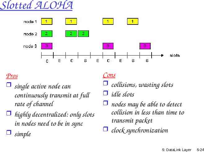
Slotted ALOHA Pros single active node can continuously transmit at full rate of channel highly decentralized: only slots in nodes need to be in sync simple Cons collisions, wasting slots idle slots nodes may be able to detect collision in less than time to transmit packet clock synchronization 5: DataLink Layer 5-24
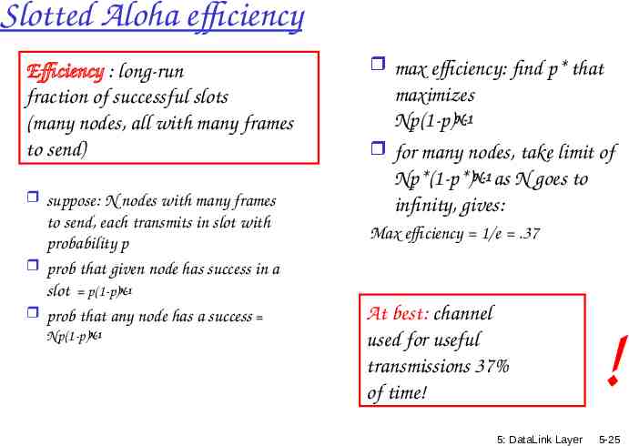
Slotted Aloha efficiency Efficiency : long-run fraction of successful slots (many nodes, all with many frames to send) suppose: N nodes with many frames to send, each transmits in slot with probability p prob that given node has success in a slot p(1-p)N-1 prob that any node has a success Np(1-p)N-1 max efficiency: find p* that maximizes Np(1-p)N-1 for many nodes, take limit of Np*(1-p*)N-1 as N goes to infinity, gives: Max efficiency 1/e .37 At best: channel used for useful transmissions 37% of time! 5: DataLink Layer ! 5-25
CSMA (Carrier Sense Multiple Access) CSMA: listen before transmit: If channel sensed idle: transmit entire frame If channel sensed busy, defer transmission 5: DataLink Layer 5-26
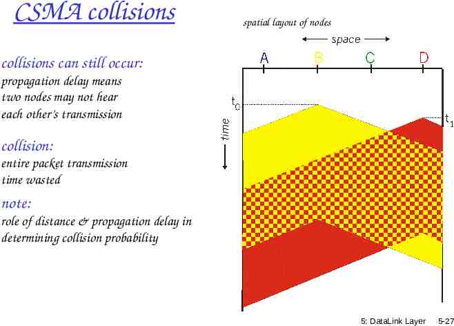
CSMA collisions spatial layout of nodes collisions can still occur: propagation delay means two nodes may not hear each other’s transmission collision: entire packet transmission time wasted note: role of distance & propagation delay in determining collision probability 5: DataLink Layer 5-27
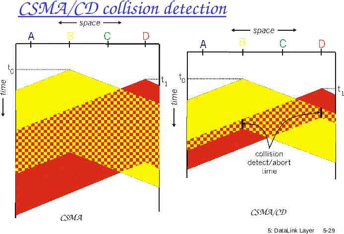
CSMA/CD (Collision Detection) CSMA/CD: carrier sensing, deferral as in CSMA collisions detected within short time colliding transmissions aborted, reducing channel wastage collision detection: easy in wired LANs: measure signal strengths, compare transmitted, received signals difficult in wireless LANs: received signal strength overwhelmed by local transmission strength (use CSMA/CA: we’ll get back to that in Ch 6) human analogy: the polite conversationalist 5: DataLink Layer 5-28
CSMA/CD collision detection CSMA CSMA/CD 5: DataLink Layer 5-29
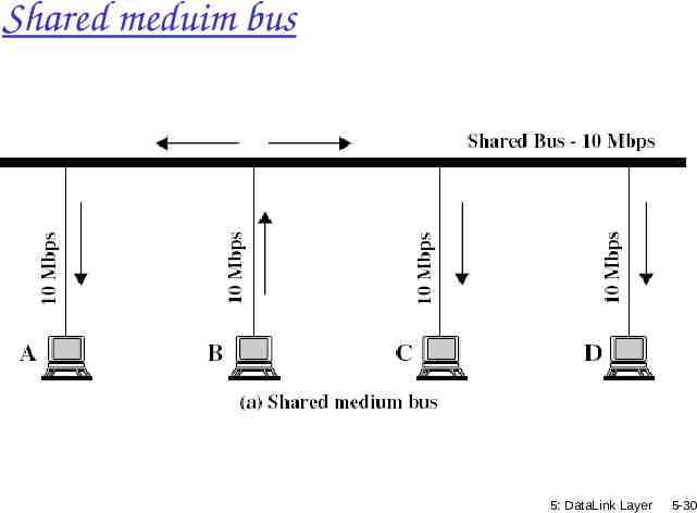
Shared meduim bus 5: DataLink Layer 5-30
More on CSMA/CD and Ethernet - uses broadcast and filtration: all stations on the bus receive the frame, but only the station with the appropriate data link D-L (MAC) destination address picks up the frame. For multicast, filteration may be done at the D-L layer or at the network layer (with more overhead) 5: DataLink Layer 5-31
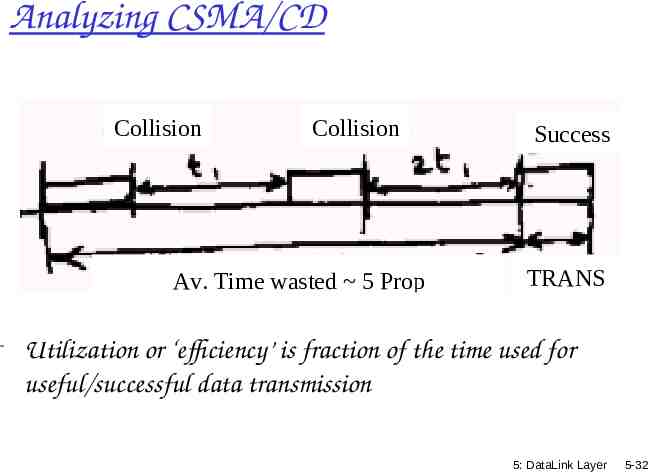
Analyzing CSMA/CD Collision Collision Av. Time wasted 5 Prop Success TRANS - Utilization or ‘efficiency’ is fraction of the time used for useful/successful data transmission 5: DataLink Layer 5-32
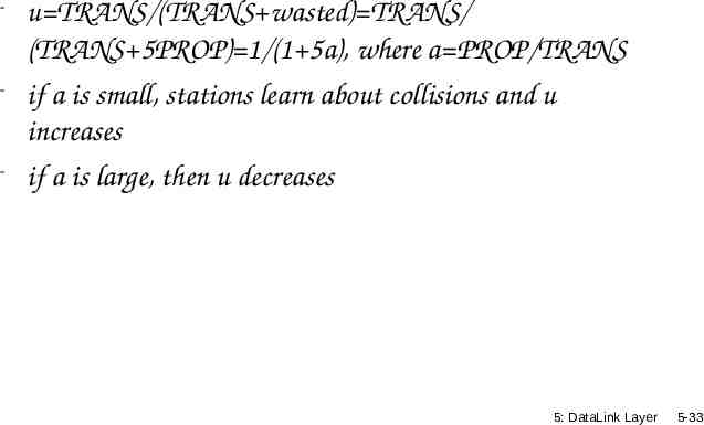
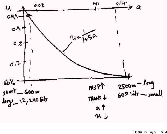
- u TRANS/(TRANS wasted) TRANS/ (TRANS 5PROP) 1/(1 5a), where a PROP/TRANS - if a is small, stations learn about collisions and u increases - if a is large, then u decreases 5: DataLink Layer 5-33
5: DataLink Layer 5-34
Collision detection in Wireless Need special equipment to detect collision at receiver We care about the collision at the reciever 1. no-collision detected at sender but collision detected at receiver 2. collision at sender but no collision at receiver Neighborhood of sender and receiver are not the same (it’s not a shared wire, but define relatively (locally) to a node [hidden terminal problem] more later 5: DataLink Layer 5-35
“Taking Turns” MAC protocols channel partitioning MAC protocols: share channel efficiently and fairly at high load inefficient at low load: delay in channel access, 1/N bandwidth allocated even if only 1 active node! Random access MAC protocols efficient at low load: single node can fully utilize channel high load: collision overhead “taking turns” protocols look for best of both worlds! 5: DataLink Layer 5-36
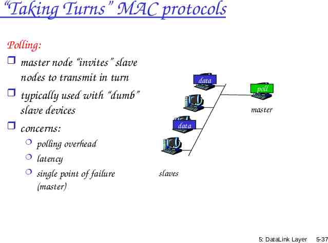
“Taking Turns” MAC protocols Polling: master node “invites” slave nodes to transmit in turn typically used with “dumb” slave devices concerns: polling overhead latency single point of failure (master) data poll master data slaves 5: DataLink Layer 5-37
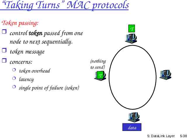
“Taking Turns” MAC protocols Token passing: control token passed from one node to next sequentially. token message concerns: token overhead latency single point of failure (token) T (nothing to send) T data 5: DataLink Layer 5-38
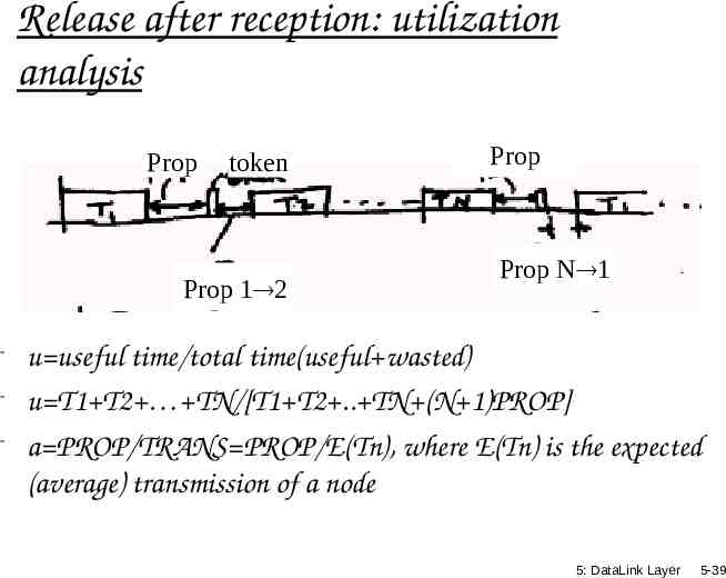
Release after reception: utilization analysis Prop token Prop 1 2 Prop Prop N 1 - u useful time/total time(useful wasted) - u T1 T2 TN/[T1 T2 . TN (N 1)PROP] - a PROP/TRANS PROP/E(Tn), where E(Tn) is the expected (average) transmission of a node 5: DataLink Layer 5-39
u Ti/( Ti (N 1)PROP) 1/(1 PROP/E(Tn)), where E(Tn) Ti/N u 1/(1 a) for token ring [compared to Ethernet u 1/(1 5a)] 5: DataLink Layer 5-40
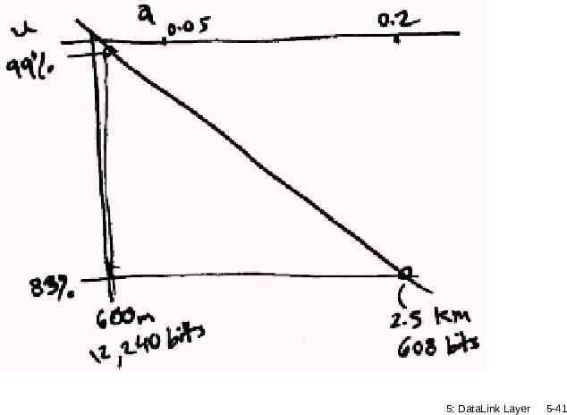
5: DataLink Layer 5-41
As the number of stations increases, less time for token passing, and u increases for release after transmission u 1/(1 a/N), where N is the number of stations 5: DataLink Layer 5-42
Summary of MAC protocols channel partitioning, by time, frequency or code Time Division, Frequency Division random access (dynamic), ALOHA, S-ALOHA, CSMA, CSMA/CD carrier sensing: easy in some technologies (wire), hard in others (wireless) CSMA/CD used in Ethernet CSMA/CA used in 802.11 taking turns polling from central site, token passing Bluetooth, FDDI, IBM Token Ring 5: DataLink Layer 5-43
LAN technologies Data link layer so far: services, error detection/correction, multiple access Next: LAN technologies Ethernet addressing switches PPP 5: DataLink Layer 5-44
Link Layer 5.1 Introduction and services 5.2 Error detection and 5.6 Link-layer switches 5.7 PPP correction 5.3Multiple access protocols 5.4 Link-Layer Addressing 5.5 Ethernet 5.8 Link Virtualization: ATM and MPLS 5: DataLink Layer 5-45
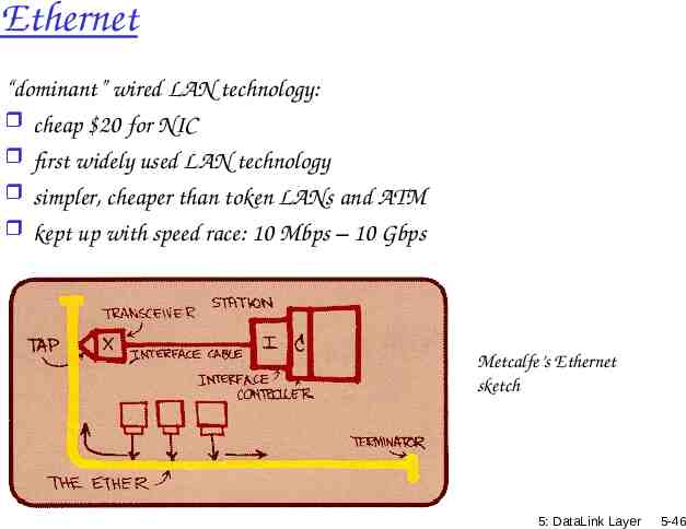
Ethernet “dominant” wired LAN technology: cheap 20 for NIC first widely used LAN technology simpler, cheaper than token LANs and ATM kept up with speed race: 10 Mbps – 10 Gbps Metcalfe’s Ethernet sketch 5: DataLink Layer 5-46
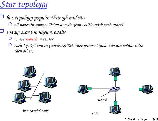
Star topology bus topology popular through mid 90s all nodes in same collision domain (can collide with each other) today: star topology prevails active switch in center each “spoke” runs a (separate) Ethernet protocol (nodes do not collide with each other) switch bus: coaxial cable star 5: DataLink Layer 5-47
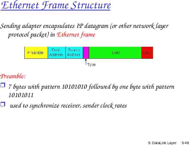
Ethernet Frame Structure Sending adapter encapsulates IP datagram (or other network layer protocol packet) in Ethernet frame Preamble: 7 bytes with pattern 10101010 followed by one byte with pattern 10101011 used to synchronize receiver, sender clock rates 5: DataLink Layer 5-48
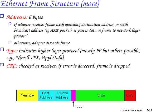
Ethernet Frame Structure (more) Addresses: 6 bytes if adapter receives frame with matching destination address, or with broadcast address (eg ARP packet), it passes data in frame to network layer protocol otherwise, adapter discards frame Type: indicates higher layer protocol (mostly IP but others possible, e.g., Novell IPX, AppleTalk) CRC: checked at receiver, if error is detected, frame is dropped 5: DataLink Layer 5-49
Ethernet: Unreliable, connectionless connectionless: No handshaking between sending and receiving NICs unreliable: receiving NIC doesn’t send acks or nacks to sending NIC stream of datagrams passed to network layer can have gaps (missing datagrams) gaps will be filled if app is using TCP otherwise, app will see gaps Ethernet’s MAC protocol: unslotted CSMA/CD 5: DataLink Layer 5-50
Ethernet CSMA/CD algorithm 1. NIC receives datagram from network layer, creates frame 2. If NIC senses channel idle, starts frame transmission. If NIC senses channel busy, waits until channel idle, then transmits. 3. If NIC transmits entire frame without detecting another transmission, NIC is done with frame ! 5: DataLink Layer 5-51
Ethernet CSMA/CD algorithm (contd.) 4. If NIC detects another transmission while transmitting, aborts and sends jam signal 5. After aborting, NIC enters exponential backoff: after mth collision, NIC chooses K at random from {0,1,2, ,2m-1}. NIC waits K·512 bit times, returns to Step 2 (channel sensing) 5: DataLink Layer 5-52
Ethernet’s CSMA/CD (more) Jam Signal: make sure all other transmitters are aware of collision; 48 bits Bit time: .1 microsec for 10 Mbps Ethernet ; for K 1023, wait time is about 50 msec See/interact with Java applet on AWL Web site: highly recommended ! Exponential Backoff: Goal: adapt retransmission attempts to estimated current load heavy load: random wait will be longer first collision: choose K from {0,1}; delay is K· 512 bit transmission times after second collision: choose K from {0,1,2,3} after ten collisions, choose K from {0,1,2,3,4, ,1023} 5: DataLink Layer 5-53
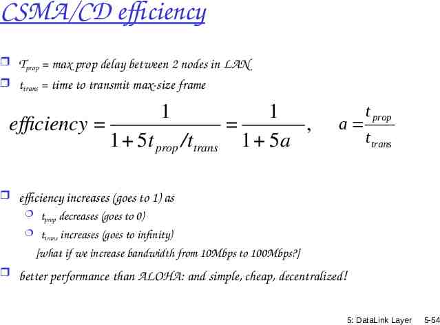
CSMA/CD efficiency Tprop max prop delay between 2 nodes in LAN ttrans time to transmit max-size frame efficiency 1 1 5t prop /ttrans 1 , 1 5a a t prop ttrans efficiency increases (goes to 1) as tprop decreases (goes to 0) ttrans increases (goes to infinity) [what if we increase bandwidth from 10Mbps to 100Mbps?] better performance than ALOHA: and simple, cheap, decentralized! 5: DataLink Layer 5-54
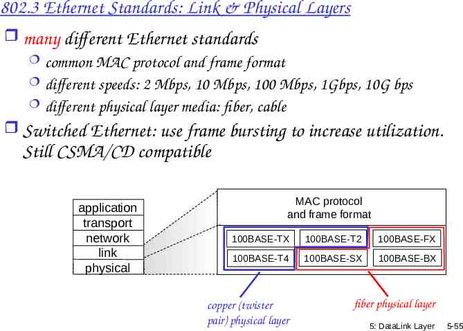
802.3 Ethernet Standards: Link & Physical Layers many different Ethernet standards common MAC protocol and frame format different speeds: 2 Mbps, 10 Mbps, 100 Mbps, 1Gbps, 10G bps different physical layer media: fiber, cable Switched Ethernet: use frame bursting to increase utilization. Still CSMA/CD compatible application transport network link physical MAC protocol and frame format 100BASE-TX 100BASE-T2 100BASE-FX 100BASE-T4 100BASE-SX 100BASE-BX copper (twister pair) physical layer fiber physical layer 5: DataLink Layer 5-55
Shared meduim bus 5: DataLink Layer 5-56
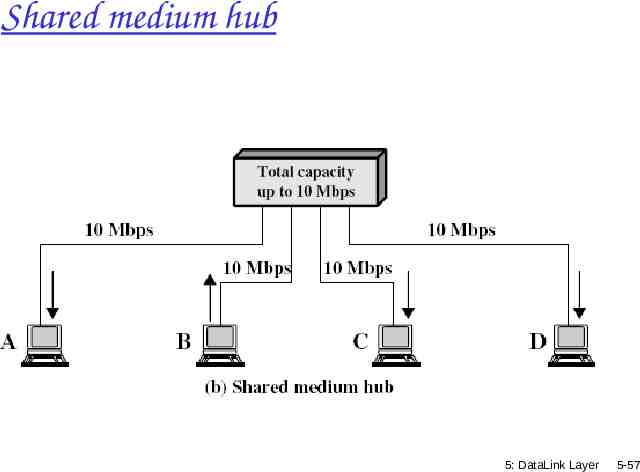
Shared medium hub 5: DataLink Layer 5-57
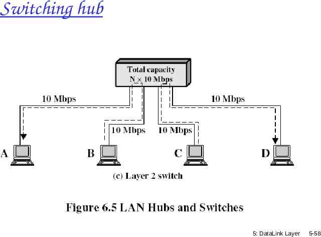
Switching hub 5: DataLink Layer 5-58
5: DataLink Layer 5-59
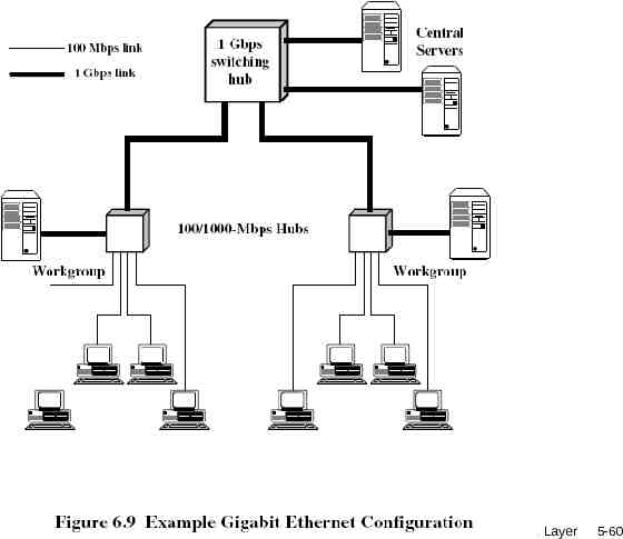
5: DataLink Layer 5-60
Link Layer 5.1 Introduction and services 5.2 Error detection and 5.6 Link-layer switches 5.7 PPP correction 5.3Multiple access protocols 5.4 Link-Layer Addressing 5.5 Ethernet 5.8 Link Virtualization: ATM, MPLS 5: DataLink Layer 5-61
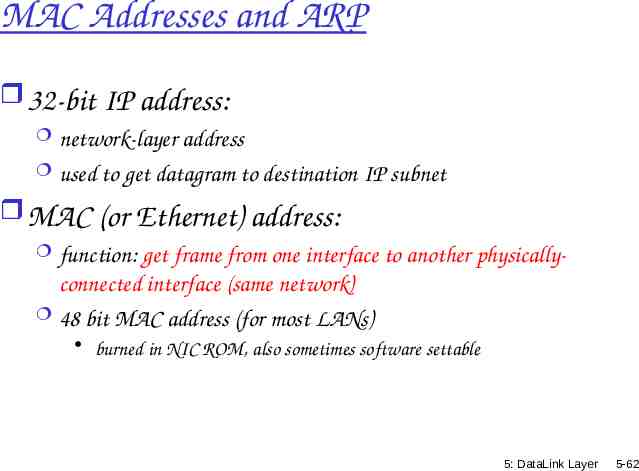
MAC Addresses and ARP 32-bit IP address: network-layer address used to get datagram to destination IP subnet MAC (or Ethernet) address: function: get frame from one interface to another physically- connected interface (same network) 48 bit MAC address (for most LANs) burned in NIC ROM, also sometimes software settable 5: DataLink Layer 5-62
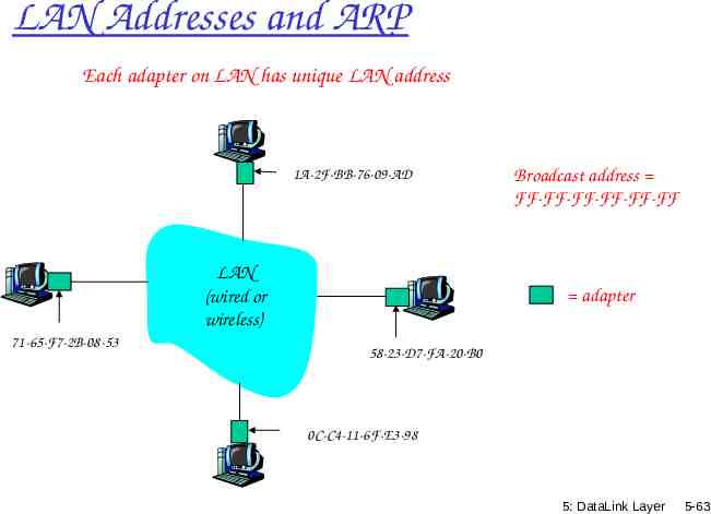
LAN Addresses and ARP Each adapter on LAN has unique LAN address 1A-2F-BB-76-09-AD LAN (wired or wireless) 71-65-F7-2B-08-53 Broadcast address FF-FF-FF-FF-FF-FF adapter 58-23-D7-FA-20-B0 0C-C4-11-6F-E3-98 5: DataLink Layer 5-63
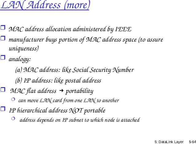
LAN Address (more) MAC address allocation administered by IEEE manufacturer buys portion of MAC address space (to assure uniqueness) analogy: (a) MAC address: like Social Security Number (b) IP address: like postal address MAC flat address portability can move LAN card from one LAN to another IP hierarchical address NOT portable address depends on IP subnet to which node is attached 5: DataLink Layer 5-64
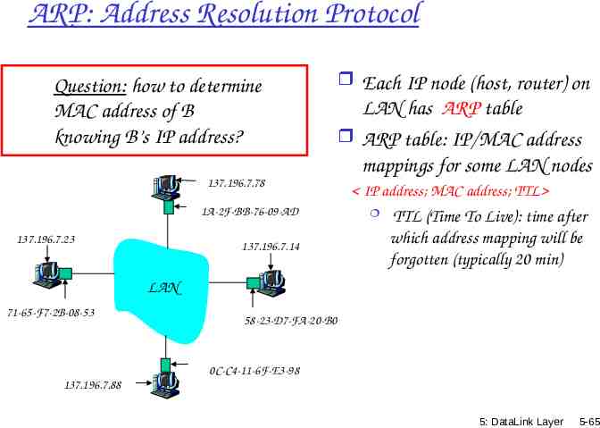
ARP: Address Resolution Protocol Question: how to determine MAC address of B knowing B’s IP address? 137.196.7.78 1A-2F-BB-76-09-AD 137.196.7.23 137.196.7.14 Each IP node (host, router) on LAN has ARP table ARP table: IP/MAC address mappings for some LAN nodes IP address; MAC address; TTL TTL (Time To Live): time after which address mapping will be forgotten (typically 20 min) LAN 71-65-F7-2B-08-53 58-23-D7-FA-20-B0 0C-C4-11-6F-E3-98 137.196.7.88 5: DataLink Layer 5-65
ARP protocol: Same LAN (network) A wants to send datagram to B, and B’s MAC address not in A’s ARP table. A broadcasts ARP query packet, containing B's IP address dest MAC address FF-FFFF-FF-FF-FF all machines on LAN receive ARP query B receives ARP packet, replies to A with its (B's) MAC address A caches (saves) IP-to-MAC address pair in its ARP table until information becomes old (times out) soft state: information that times out (goes away) unless refreshed ARP is “plug-and-play”: nodes create their ARP tables without intervention from net administrator frame sent to A’s MAC address (unicast) 5: DataLink Layer 5-66
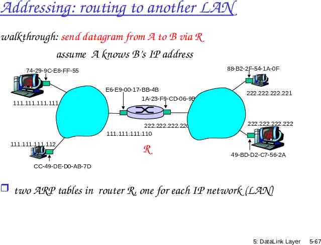
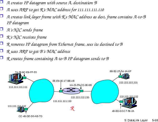
Addressing: routing to another LAN walkthrough: send datagram from A to B via R assume A knows B’s IP address 88-B2-2F-54-1A-0F 74-29-9C-E8-FF-55 A 111.111.111.111 E6-E9-00-17-BB-4B 1A-23-F9-CD-06-9B 222.222.222.220 111.111.111.110 111.111.111.112 R 222.222.222.221 222.222.222.222 B 49-BD-D2-C7-56-2A CC-49-DE-D0-AB-7D two ARP tables in router R, one for each IP network (LAN) 5: DataLink Layer 5-67
A creates IP datagram with source A, destination B A uses ARP to get R’s MAC address for 111.111.111.110 A creates link-layer frame with R's MAC address as dest, frame contains A-to-B IP datagram A’s NIC sends frame R’s NIC receives frame R removes IP datagram from Ethernet frame, sees its destined to B R uses ARP to get B’s MAC address R creates frame containing A-to-B IP datagram sends to B 88-B2-2F-54-1A-0F 74-29-9C-E8-FF-55 A E6-E9-00-17-BB-4B 111.111.111.111 1A-23-F9-CD-06-9B 222.222.222.220 111.111.111.110 111.111.111.112 R 222.222.222.221 222.222.222.222 B 49-BD-D2-C7-56-2A CC-49-DE-D0-AB-7D 5: DataLink Layer 5-68
Link Layer 5.1 Introduction and services 5.2 Error detection and 5.6 Link-layer switches 5.7 PPP correction 5.3 Multiple access protocols 5.4 Link-layer Addressing 5.5 Ethernet 5.8 Link Virtualization: ATM, MPLS 5: DataLink Layer 5-69
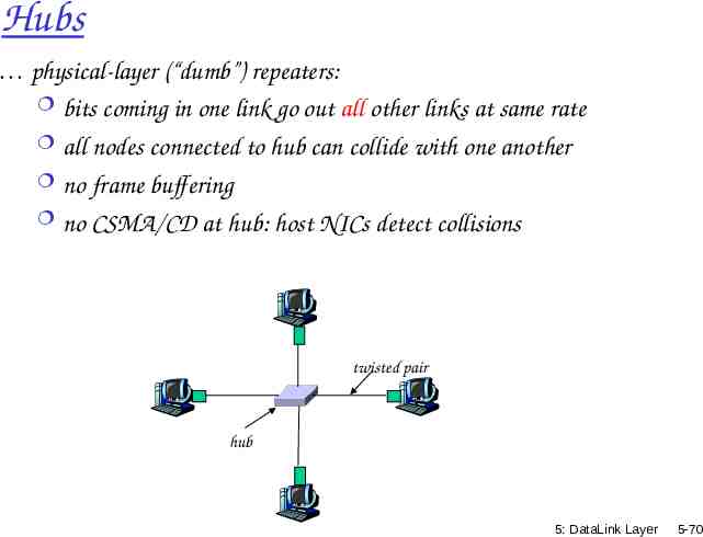
Hubs physical-layer (“dumb”) repeaters: bits coming in one link go out all other links at same rate all nodes connected to hub can collide with one another no frame buffering no CSMA/CD at hub: host NICs detect collisions twisted pair hub 5: DataLink Layer 5-70
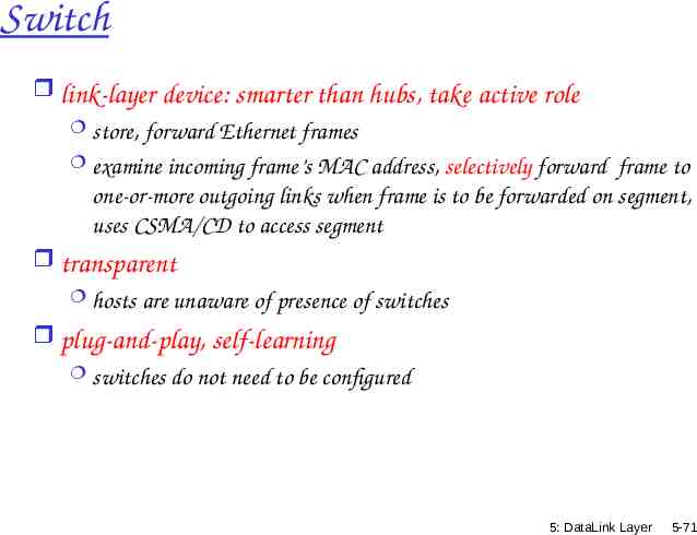
Switch link-layer device: smarter than hubs, take active role store, forward Ethernet frames examine incoming frame’s MAC address, selectively forward frame to one-or-more outgoing links when frame is to be forwarded on segment, uses CSMA/CD to access segment transparent hosts are unaware of presence of switches plug-and-play, self-learning switches do not need to be configured 5: DataLink Layer 5-71
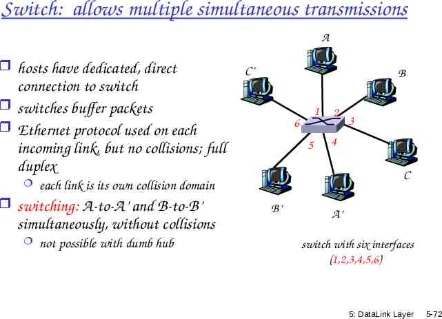
Switch: allows multiple simultaneous transmissions A hosts have dedicated, direct C’ B connection to switch switches buffer packets Ethernet protocol used on each incoming link, but no collisions; full duplex 6 5 2 simultaneously, without collisions not possible with dumb hub 3 4 C each link is its own collision domain switching: A-to-A’ and B-to-B’ 1 B’ A’ switch with six interfaces (1,2,3,4,5,6) 5: DataLink Layer 5-72
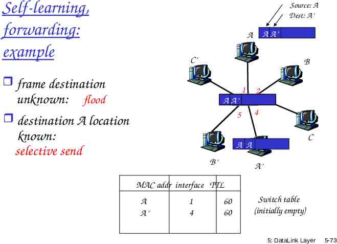
Self-learning, forwarding: example Source: A Dest: A’ A A’ A C’ B frame destination unknown: flood A6A’ 1 5 destination A location known: selective send 2 3 4 C A’ A B’ A’ MAC addr interface TTL A A’ 1 4 60 60 Switch table (initially empty) 5: DataLink Layer 5-73
Link Layer 5.1 Introduction and services 5.2 Error detection and 5.6 Hubs and switches 5.7 PPP correction 5.3Multiple access protocols 5.4 Link-Layer Addressing 5.5 Ethernet 5.8 Link Virtualization: ATM and MPLS 5: DataLink Layer 5-74
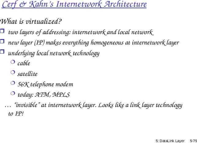
Cerf & Kahn’s Internetwork Architecture What is virtualized? two layers of addressing: internetwork and local network new layer (IP) makes everything homogeneous at internetwork layer underlying local network technology cable satellite 56K telephone modem today: ATM, MPLS “invisible” at internetwork layer. Looks like a link layer technology to IP! 5: DataLink Layer 5-75
ATM and MPLS ATM, MPLS separate networks in their own right different service models, addressing, routing from Internet viewed by Internet as logical link connecting IP routers just like dialup link is really part of separate network (telephone network) ATM, MPLS: of technical interest in their own right 5: DataLink Layer 5-76
Asynchronous Transfer Mode: ATM 1990’s/00 standard for high-speed (155Mbps to 622 Mbps and higher) Broadband Integrated Service Digital Network architecture Goal: integrated, end-end transport of carry voice, video, data meeting timing/QoS requirements of voice, video (versus Internet best-effort model) “next generation” telephony: technical roots in telephone world packet-switching (fixed length packets, called “cells”) using virtual circuits 5: DataLink Layer 5-77
Virtual circuit Example: ATM - routing at call set-up, prior to data transfer - path is not dedicated, still uses store & forward, statistical multiplexing - no routing decision per packet - packets follow same path 5: DataLink Layer 5-78
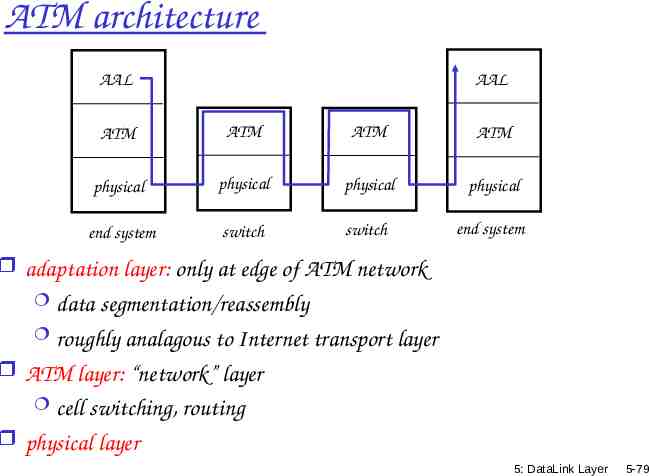
ATM architecture AAL AAL ATM ATM ATM ATM physical physical physical physical end system switch switch end system adaptation layer: only at edge of ATM network data segmentation/reassembly roughly analagous to Internet transport layer ATM layer: “network” layer cell switching, routing physical layer 5: DataLink Layer 5-79
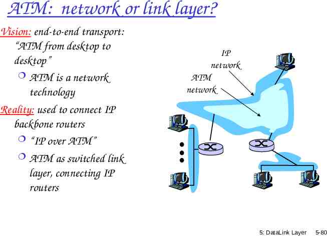
ATM: network or link layer? Vision: end-to-end transport: “ATM from desktop to desktop” ATM is a network technology Reality: used to connect IP backbone routers “IP over ATM” ATM as switched link layer, connecting IP routers IP network ATM network 5: DataLink Layer 5-80
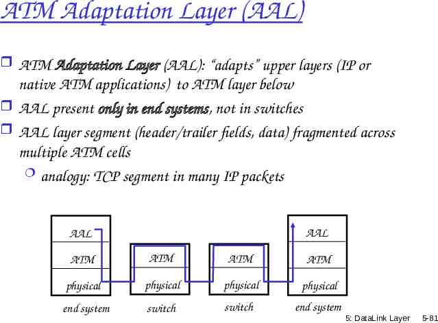
ATM Adaptation Layer (AAL) ATM Adaptation Layer (AAL): “adapts” upper layers (IP or native ATM applications) to ATM layer below AAL present only in end systems, not in switches AAL layer segment (header/trailer fields, data) fragmented across multiple ATM cells analogy: TCP segment in many IP packets AAL AAL ATM ATM ATM ATM physical physical physical physical end system switch switch end system 5: DataLink Layer 5-81
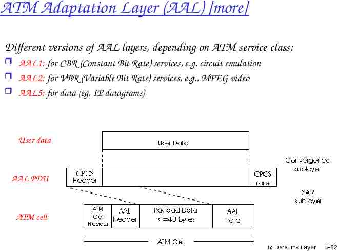
ATM Adaptation Layer (AAL) [more] Different versions of AAL layers, depending on ATM service class: AAL1: for CBR (Constant Bit Rate) services, e.g. circuit emulation AAL2: for VBR (Variable Bit Rate) services, e.g., MPEG video AAL5: for data (eg, IP datagrams) User data AAL PDU ATM cell 5: DataLink Layer 5-82
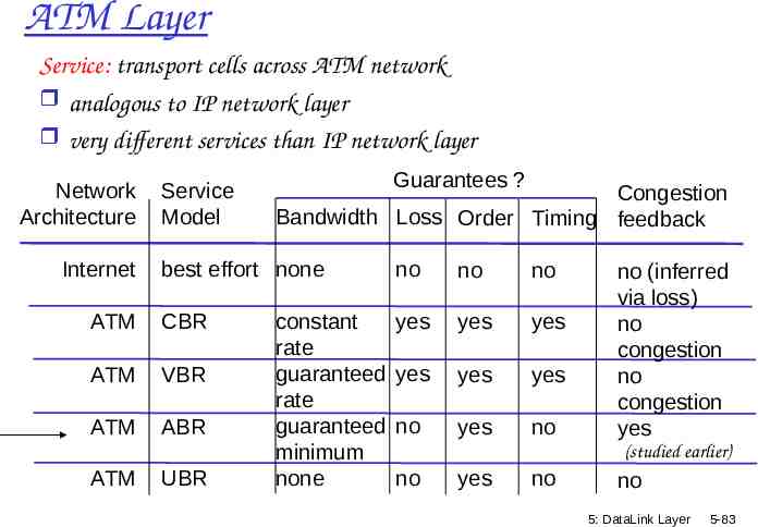
ATM Layer Service: transport cells across ATM network analogous to IP network layer very different services than IP network layer Network Architecture Internet Service Model Congestion Bandwidth Loss Order Timing feedback best effort none ATM CBR ATM VBR ATM ABR ATM Guarantees ? UBR constant rate guaranteed rate guaranteed minimum none no no no yes yes yes yes yes yes no yes no no (inferred via loss) no congestion no congestion yes (studied earlier) no yes no no 5: DataLink Layer 5-83
ATM Layer: Virtual Circuits VC transport: cells carried on VC from source to dest call setup, teardown for each call before data can flow each packet carries VC identifier (not destination ID) every switch on source-dest path maintain “state” for each passing connection link,switch resources (bandwidth, buffers) may be allocated to VC: to get circuit-like perf. Permanent VCs (PVCs) long lasting connections typically: “permanent” route between to IP routers Switched VCs (SVC): dynamically set up on per-call basis 5: DataLink Layer 5-84
ATM VCs Advantages of ATM VC approach: QoS performance guarantee for connection mapped to VC (bandwidth, delay, delay jitter) Drawbacks of ATM VC approach: Inefficient support of datagram traffic one PVC between each source/dest pair) does not scale (n.(n-1) connections needed) SVC introduces call setup latency, processing overhead for short lived connections VCI: VC Identifier, used for routing/switching Has local significance (unlike IP addresses) Identifies a segment of a path for a flow (or bundle of flows, called virtual path VP), to simplify switching May change from one link to another 5: DataLink Layer 5-85
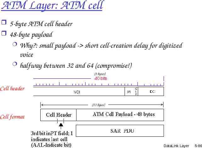
ATM Layer: ATM cell 5-byte ATM cell header 48-byte payload Why?: small payload - short cell-creation delay for digitized voice halfway between 32 and 64 (compromise!) (5 bytes) Cell header (53 bytes) Cell format 5: DataLink Layer 5-86
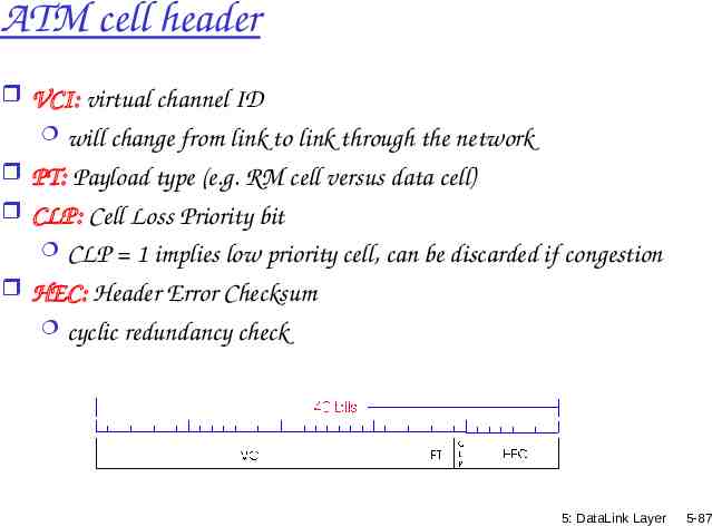
ATM cell header VCI: virtual channel ID will change from link to link through the network PT: Payload type (e.g. RM cell versus data cell) CLP: Cell Loss Priority bit CLP 1 implies low priority cell, can be discarded if congestion HEC: Header Error Checksum cyclic redundancy check 5: DataLink Layer 5-87
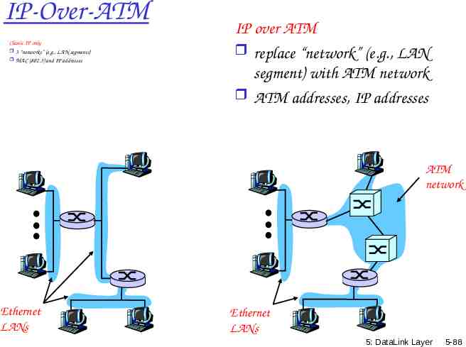
IP-Over-ATM Classic IP only 3 “networks” (e.g., LAN segments) MAC (802.3) and IP addresses IP over ATM replace “network” (e.g., LAN segment) with ATM network ATM addresses, IP addresses ATM network Ethernet LANs Ethernet LANs 5: DataLink Layer 5-88
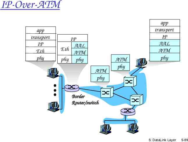
IP-Over-ATM app transport IP Eth phy IP AAL Eth ATM phy phy ATM phy ATM phy app transport IP AAL ATM phy Border Router/switch 5: DataLink Layer 5-89
Datagram Journey in IP-over-ATM Network at Source Host: IP layer maps between IP, ATM dest address (using ARP) passes datagram to AAL5 AAL5 encapsulates data, segments cells, passes to ATM layer ATM network: moves cell along VC to destination at Destination Host: AAL5 reassembles cells into original datagram if CRC OK, datagram is passed to IP 5: DataLink Layer 5-90
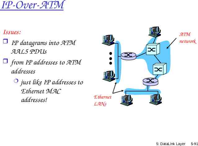
IP-Over-ATM Issues: IP datagrams into ATM AAL5 PDUs from IP addresses to ATM addresses just like IP addresses to Ethernet MAC addresses! ATM network Ethernet LANs 5: DataLink Layer 5-91