Architectural Design, Distributed Systems Architectures Lectures 17


56 Slides470.00 KB
Architectural Design, Distributed Systems Architectures Lectures 17 and 18 Ian Sommerville 2000 Software Engineering, COMP201 Slide 1
Architectural Design - Establishing the overall structure of a software system Topics covered: System structuring Control models Modular decomposition Architectural Design Multiprocessor architectures Client-server architectures Distributed object architectures Ian Sommerville 2000 Software Engineering, COMP201 Distributed Systems Architectures Slide 2
Software architecture The design process for identifying the subsystems making up a system and the framework for sub-system control and communication is architectural design The output of this design process is a description of the software architecture Ian Sommerville 2000 Software Engineering, COMP201 Slide 3
Architectural design An early stage of the system design process Represents the link between specification and design processes Often carried out in parallel with some specification activities It involves identifying major system components and their communications Ian Sommerville 2000 Software Engineering, COMP201 Slide 4
Architectural design process System structuring Control modelling The system is decomposed into several principal sub-systems and communications between these sub-systems are identified A model of the control relationships between the different parts of the system is established Modular decomposition The identified sub-systems are decomposed into modules Ian Sommerville 2000 Software Engineering, COMP201 Slide 5
Sub-systems and modules A sub-system is a system in its own right whose operation is independent of the services provided by other sub-systems. A module is a system component that provides services to other components but would not normally be considered as a separate system Ian Sommerville 2000 Software Engineering, COMP201 Slide 6
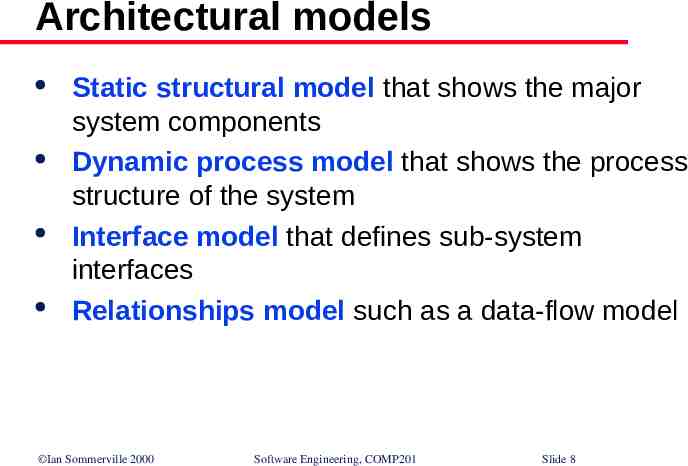
Architectural models Different architectural models may be produced during the design process Each model presents different perspectives on the architecture: Static structural model Dynamic process model Interface model Relationships model Ian Sommerville 2000 Software Engineering, COMP201 Slide 7
Architectural models Static structural model that shows the major system components Dynamic process model that shows the process structure of the system Interface model that defines sub-system interfaces Relationships model such as a data-flow model Ian Sommerville 2000 Software Engineering, COMP201 Slide 8
System structuring Concerned with decomposing the system into interacting sub-systems The architectural design is normally expressed as a block diagram presenting an overview of the system structure (More specific models showing how sub-systems share data, are distributed and interface with each other may also be developed) Ian Sommerville 2000 Software Engineering, COMP201 Slide 9
Packing robot control system Vision system Object identification system Arm controller Gripper controller Packaging selection system Packing system Ian Sommerville 2000 Software Engineering, COMP201 Conveyor controller Slide 10
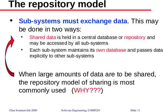
The repository model Sub-systems must exchange data. This may be done in two ways: Shared data is held in a central database or repository and may be accessed by all sub-systems Each sub-system maintains its own database and passes data explicitly to other sub-systems When large amounts of data are to be shared, the repository model of sharing is most commonly used (WHY?) Ian Sommerville 2000 Software Engineering, COMP201 Slide 11
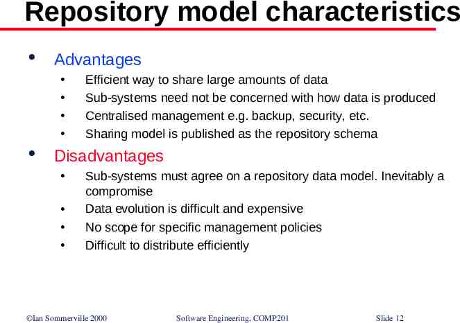
Repository model characteristics Advantages Efficient way to share large amounts of data Sub-systems need not be concerned with how data is produced Centralised management e.g. backup, security, etc. Sharing model is published as the repository schema Disadvantages Sub-systems must agree on a repository data model. Inevitably a compromise Data evolution is difficult and expensive No scope for specific management policies Difficult to distribute efficiently Ian Sommerville 2000 Software Engineering, COMP201 Slide 12
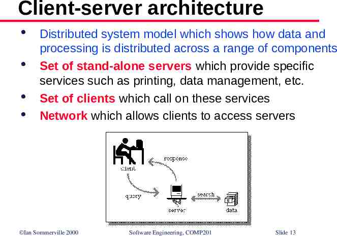
Client-server architecture Distributed system model which shows how data and processing is distributed across a range of components Set of stand-alone servers which provide specific services such as printing, data management, etc. Set of clients which call on these services Network which allows clients to access servers Ian Sommerville 2000 Software Engineering, COMP201 Slide 13
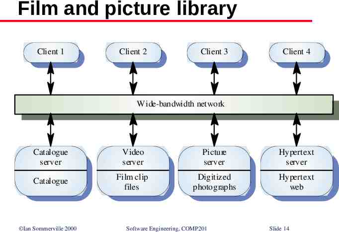
Film and picture library Client 1 Client 2 Client 3 Client 4 Wide-bandwidth network Catalogue server Video server Picture server Hypertext server Catalogue Film clip files Digitiz ed photographs Hypertext web Ian Sommerville 2000 Software Engineering, COMP201 Slide 14
Client-server characteristics Advantages Distribution of data is straightforward Makes effective use of networked systems. May require cheaper hardware Easy to add new servers or upgrade existing servers Disadvantages No shared data model so sub-systems use different data organisation. data interchange may be inefficient Redundant management in each server No central register of names and services - it may be hard to find out what servers and services are available Ian Sommerville 2000 Software Engineering, COMP201 Slide 15
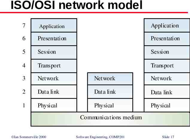
Abstract machine model - Used to model the interfacing of sub-systems Organises the system into a set of layers (or abstract machines) each of which provide a set of services Supports the incremental development of subsystems in different layers. When a layer interface changes, only the adjacent layer is affected However, often difficult to structure systems in this way Ian Sommerville 2000 Software Engineering, COMP201 Slide 16
ISO/OSI network model 7 Application Application Application 6 Presentation Presentation 5 Session Session 4 Transport Transport 3 Network Network Network 2 Data link Data link Data link 1 Physical Physical Physical Communica tions medium Ian Sommerville 2000 Software Engineering, COMP201 Slide 17
Control models Are concerned with the control flow between sub systems. Distinct from the system decomposition model Centralised control One sub-system has overall responsibility for control and starts and stops other sub-systems Event-based control Each sub-system can respond to externally generated events from other sub-systems or the system’s environment Ian Sommerville 2000 Software Engineering, COMP201 Slide 18
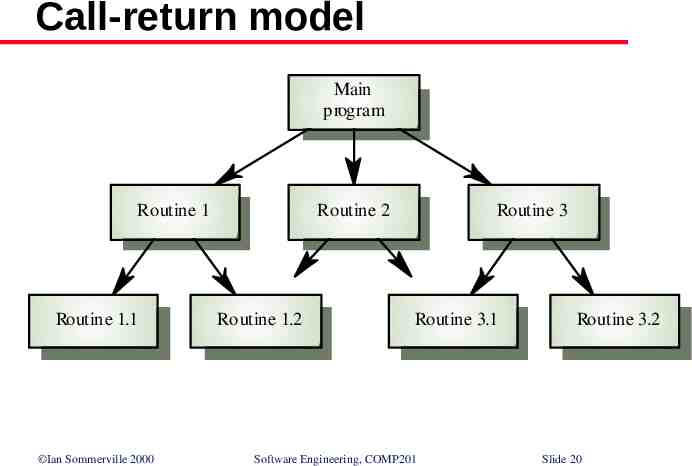
Centralised control A control sub-system takes responsibility for managing the execution of other sub-systems Call-return model Top-down subroutine model where control starts at the top of a subroutine hierarchy and moves downwards. Applicable to sequential systems Manager model Applicable to concurrent systems. One system component controls the stopping, starting and coordination of other system processes. Can be implemented in sequential systems as a case statement Ian Sommerville 2000 Software Engineering, COMP201 Slide 19
Call-return model Main program Routine 1 Routine 1.1 Ian Sommerville 2000 Routine 2 Routine 1.2 Routine 3 Routine 3.1 Software Engineering, COMP201 Routine 3.2 Slide 20
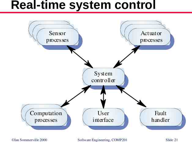
Real-time system control Sensor processes Actuator processes System contr oller Computation processes Ian Sommerville 2000 User interface Software Engineering, COMP201 Fault handler Slide 21
Event-driven systems Driven by externally generated events where the timing of the event is out with the control of the sub-systems which process the event Two principal event-driven models Broadcast models. An event is broadcast to all sub-systems. Any sub-system which can handle the event may do so Interrupt-driven models. Used in real-time systems where interrupts are detected by an interrupt handler and passed to some other component for processing Ian Sommerville 2000 Software Engineering, COMP201 Slide 22
Broadcast model Effective in integrating sub-systems on different computers in a network Sub-systems register an interest in specific events. When these occur, control is transferred to the subsystem which can handle the event Control policy is not embedded in the event and message handler. Sub-systems decide on events of interest to them (!!!) However, sub-systems don’t know if or when an event will be handled Ian Sommerville 2000 Software Engineering, COMP201 Slide 23
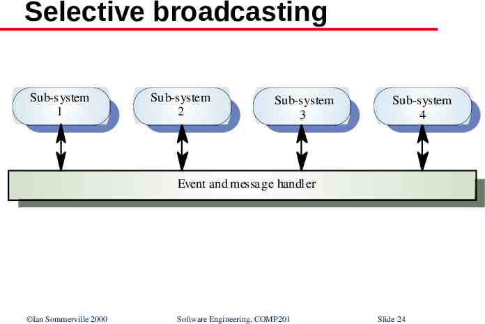
Selective broadcasting Sub-system 1 Sub-system 2 Sub-system 3 Sub-system 4 Event and messa ge handler Ian Sommerville 2000 Software Engineering, COMP201 Slide 24
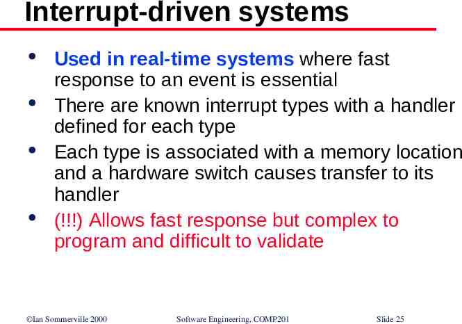
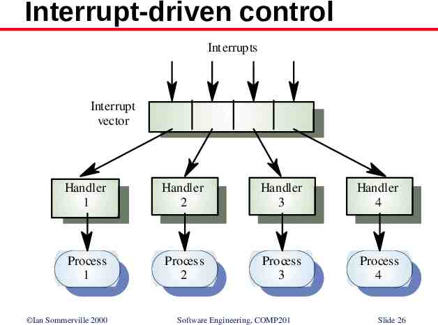
Interrupt-driven systems Used in real-time systems where fast response to an event is essential There are known interrupt types with a handler defined for each type Each type is associated with a memory location and a hardware switch causes transfer to its handler (!!!) Allows fast response but complex to program and difficult to validate Ian Sommerville 2000 Software Engineering, COMP201 Slide 25
Interrupt-driven control Interrupts Interrupt vector Handler 1 Handler 2 Handler 3 Handler 4 Process 1 Process 2 Process 3 Process 4 Ian Sommerville 2000 Software Engineering, COMP201 Slide 26
Modular decomposition Another structural level where sub-systems are decomposed into modules Two modular decomposition models covered An object model where the system is decomposed into interacting objects A data-flow model where the system is decomposed into functional modules which transform inputs to outputs. Also known as the pipeline model If possible, decisions about concurrency should be delayed until modules are implemented Ian Sommerville 2000 Software Engineering, COMP201 Slide 27
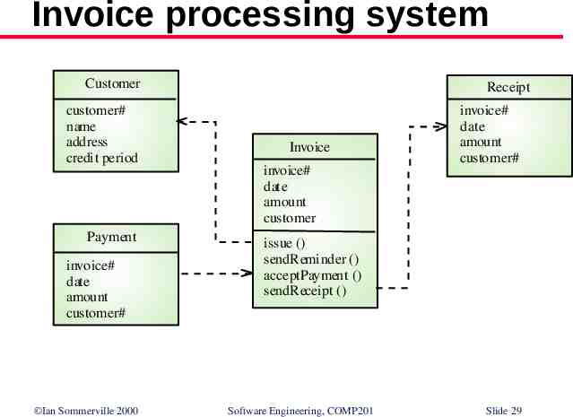
Object models Structure the system into a set of loosely coupled objects with well-defined interfaces Object-oriented decomposition is concerned with identifying object classes, their attributes and operations When implemented, objects are created from these classes and some control model used to coordinate object operations Ian Sommerville 2000 Software Engineering, COMP201 Slide 28
Invoice processing system Customer customer# name address credit period Payment invoice# date amount customer# Ian Sommerville 2000 Receipt Invoice invoice# date amount customer invoice# date amount customer# issue () sendR eminder () acceptPayment () sendR eceipt () Software Engineering, COMP201 Slide 29
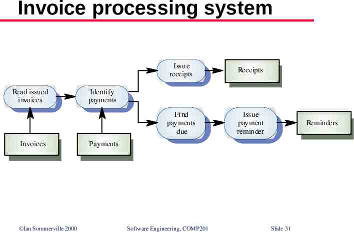
Data-flow models Functional transformations process their inputs to produce outputs May be referred to as a pipe and filter model (as in UNIX shell) Variants of this approach are very common. When transformations are sequential, this is a batch sequential model which is extensively used in data processing systems Not really suitable for interactive systems Ian Sommerville 2000 Software Engineering, COMP201 Slide 30
Invoice processing system Read issued invoices Invoices Ian Sommerville 2000 Issue receipts Receipts Find payments due Issue payment reminder Identify payments Reminders Payments Software Engineering, COMP201 Slide 31
Distributed Systems Architectures Architectural design for software that executes on more than one processor Ian Sommerville 2000 Software Engineering, COMP201 Slide 32
Distributed systems Virtually all large computer-based systems are now distributed systems Information processing is distributed over several computers rather than confined to a single machine Distributed software engineering is now very important Ian Sommerville 2000 Software Engineering, COMP201 Slide 33
System types Personal systems that are not distributed and that are designed to run on a personal computer or workstation. Embedded systems that run on a single processor or on an integrated group of processors. Distributed systems where the system software runs on a loosely integrated group of cooperating processors linked by a network. Ian Sommerville 2000 Software Engineering, COMP201 Slide 34
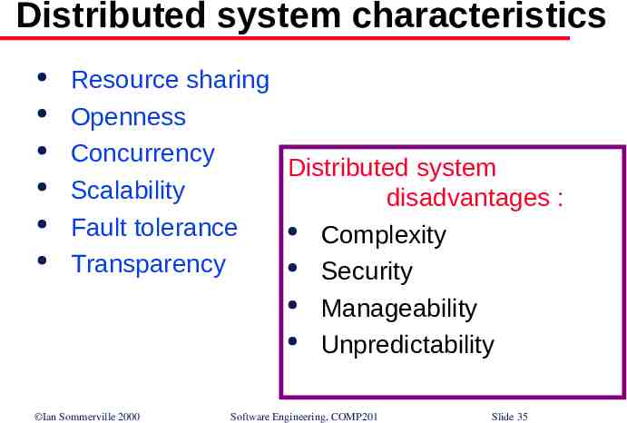
Distributed system characteristics Resource sharing Openness Concurrency Distributed system Scalability disadvantages : Fault tolerance Complexity Transparency Security Manageability Unpredictability Ian Sommerville 2000 Software Engineering, COMP201 Slide 35
Distributed systems archiectures Client-server architectures Distributed services which are called on by clients. Servers that provide services are treated differently from clients that use services Distributed object architectures No distinction between clients and servers. Any object on the system may provide and use services from other objects Ian Sommerville 2000 Software Engineering, COMP201 Slide 36
Middleware Software that manages and supports the different components of a distributed system. In essence, it sits in the middle of the system Middleware is usually off-the-shelf rather than specially written software Examples Transaction processing monitors Data converters Communication controllers Ian Sommerville 2000 Software Engineering, COMP201 Slide 37
1. Multiprocessor architectures Simplest distributed system model System composed of multiple processes which may (but need not) execute on different processors Architectural model of many large real-time systems Distribution of process to processor may be preordered or may be under the control of a dispatcher Ian Sommerville 2000 Software Engineering, COMP201 Slide 38
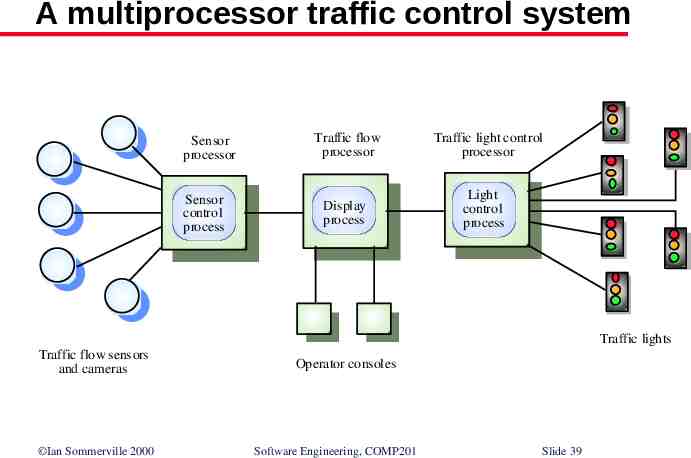
A multiprocessor traffic control system Sensor processor Sensor control process Traffic flow processor Display process Traffic light control processor Light control process Traffic lights Traffic flow sensors and cameras Ian Sommerville 2000 Operator consoles Software Engineering, COMP201 Slide 39
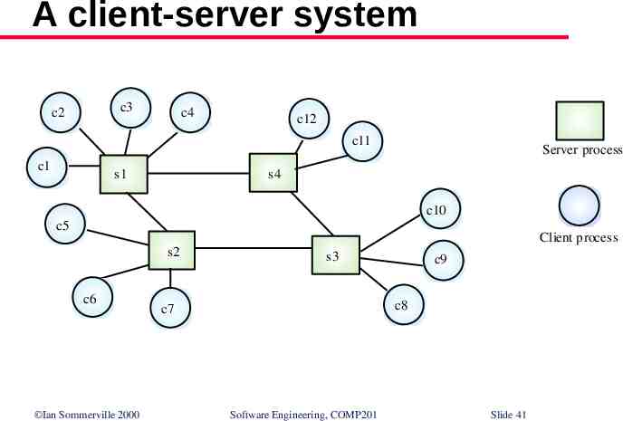
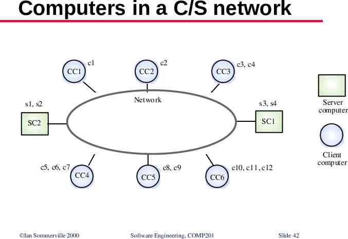
2. Client-server architectures The application is modelled as a set of services that are provided by servers and a set of clients that use these services Clients know of servers but servers need not know of clients Clients and servers are logical processes The mapping of processors to processes is not necessarily 1 : 1 Ian Sommerville 2000 Software Engineering, COMP201 Slide 40
A client-server system c3 c2 c4 c12 c11 c1 s1 Server process s4 c10 c5 Client process s2 c6 Ian Sommerville 2000 s3 c9 c8 c7 Software Engineering, COMP201 Slide 41
Computers in a C/S network c1 CC1 c2 CC2 CC3 Network s1, s2 c3, c4 Server computer s3, s4 SC1 SC2 c5, c6, c7 CC4 Ian Sommerville 2000 c8, c9 CC5 Client computer c10, c11, c12 CC6 Software Engineering, COMP201 Slide 42
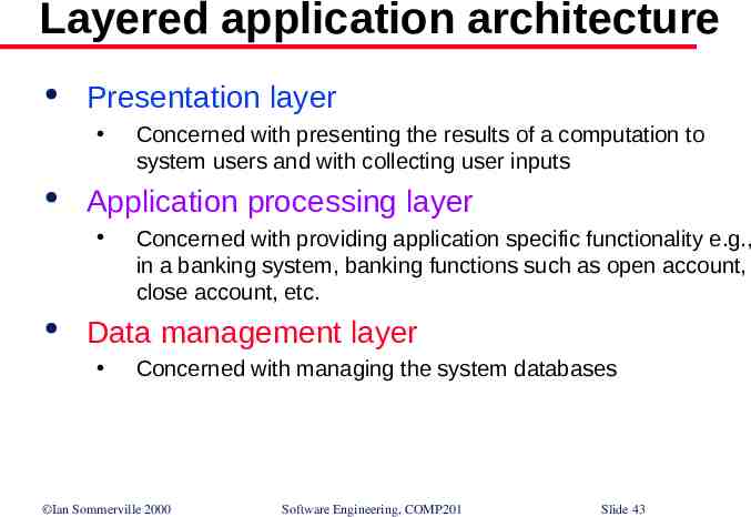
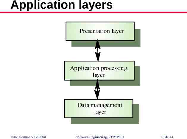
Layered application architecture Presentation layer Application processing layer Concerned with presenting the results of a computation to system users and with collecting user inputs Concerned with providing application specific functionality e.g., in a banking system, banking functions such as open account, close account, etc. Data management layer Concerned with managing the system databases Ian Sommerville 2000 Software Engineering, COMP201 Slide 43
Application layers Presentation layer Application processing layer Data management layer Ian Sommerville 2000 Software Engineering, COMP201 Slide 44
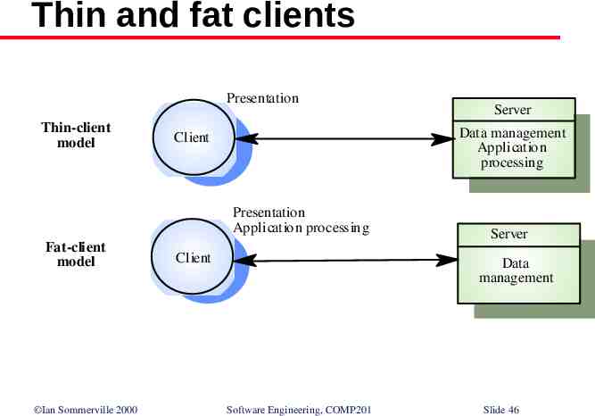
Thin and fat clients Thin-client model In a thin-client model, all of the application processing and data management is carried out on the server. The client is simply responsible for running the presentation software. Fat-client model In this model, the server is only responsible for data management. The software on the client implements the application logic and the interactions with the system user. Ian Sommerville 2000 Software Engineering, COMP201 Slide 45
Thin and fat clients Presentation Thin-client model Data management Application processing Client Presentation Application processing Fat-client model Ian Sommerville 2000 Server Client Server Data management Software Engineering, COMP201 Slide 46
Thin client model Used when legacy systems are migrated to client server architectures. The legacy system acts as a server in its own right with a graphical interface implemented on a client A major disadvantage is that it places a heavy processing load on both the server and the network Ian Sommerville 2000 Software Engineering, COMP201 Slide 47
Fat client model More processing is delegated to the client as the application processing is locally executed Most suitable for new C/S systems where the capabilities of the client system are known in advance More complex than a thin client model especially for management. New versions of the application have to be installed on all clients Ian Sommerville 2000 Software Engineering, COMP201 Slide 48
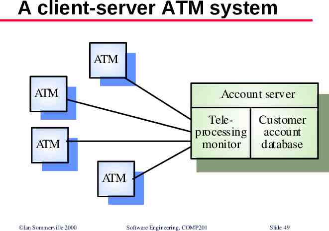
A client-server ATM system ATM ATM Account server TeleCustomer processing account monitor database ATM ATM Ian Sommerville 2000 Software Engineering, COMP201 Slide 49
Three-tier architectures In a three-tier architecture, each of the application architecture layers may execute on a separate processor Allows for better performance than a thin-client approach and is simpler to manage than a fatclient approach A more scalable architecture - as demands increase, extra servers can be added Ian Sommerville 2000 Software Engineering, COMP201 Slide 50
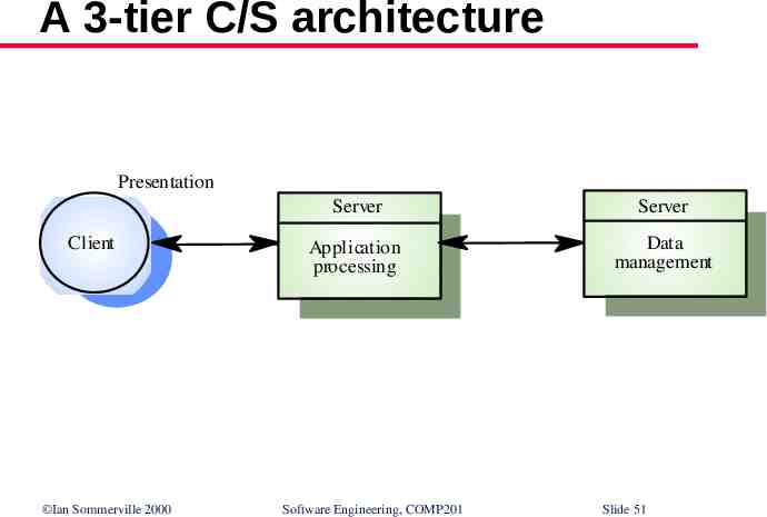
A 3-tier C/S architecture Presentation Client Ian Sommerville 2000 Server Server Application processing Data management Software Engineering, COMP201 Slide 51
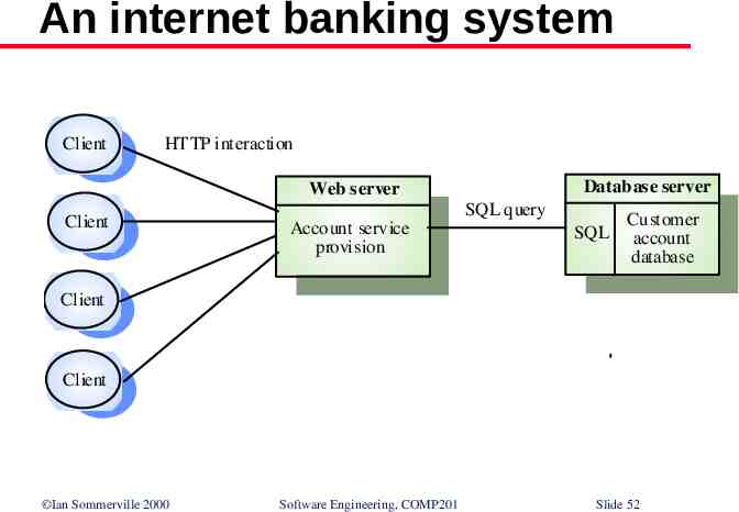
An internet banking system Client HTTP interaction Datab ase server Web server Client SQL query Account service provision SQL Customer account database Client Client Ian Sommerville 2000 Software Engineering, COMP201 Slide 52
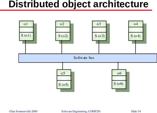
3. Distributed object architectures There is no distinction in a distributed object architectures between clients and servers Each distributable entity is an object that provides services to other objects and receives services from other objects Object communication is through a middleware system called an object request broker (software bus) However, more complex to design than C/S systems Ian Sommerville 2000 Software Engineering, COMP201 Slide 53
Distributed object architecture o1 o2 o3 o4 S (o1) S (o2) S (o3) S (o4) Software bus Ian Sommerville 2000 o5 o6 S (o5) S (o6) Software Engineering, COMP201 Slide 54
Advantages of distributed object architecture It allows the system designer to delay decisions on where and how services should be provided It is a very open system architecture that allows new resources to be added to it as required The system is flexible and scaleable It is possible to reconfigure the system dynamically with objects migrating across the network as required Ian Sommerville 2000 Software Engineering, COMP201 Slide 55
Uses of distributed object architecture As a logical model that allows you to structure and organise the system. In this case, you think about how to provide application functionality solely in terms of services and combinations of services As a flexible approach to the implementation of client-server systems. The logical model of the system is a client-server model but both clients and servers are realised as distributed objects communicating through a software bus Ian Sommerville 2000 Software Engineering, COMP201 Slide 56